
GUMROAD eBook link:-
BY SHAILENDRA KUMAR VERMA
| 1. | CHALLENGING SYLLOGISM |
| https://skverma29.gumroad.com/l/ktxvzi | |
| 2. | STRAIT OF HORMUZ: STRATEGIC & ECONOMIC ROLE |
| https://skverma29.gumroad.com/l/upobrv | |
| 4. | STATIC GENERAL KNOWLEDGE |
| https://skverma29.gumroad.com/l/kzmca | |
| 5. | SSC ENGLISH PREVIOUS YEAR QUESTIONS MCQ |
| https://skverma29.gumroad.com/l/vtotyp | |
| 6. | SSC REASONING PREVIOUS YEAR QUESTIONS MCQ |
| https://skverma29.gumroad.com/l/fsyvp | |
| 7. | SSC MATH PREVIOUS YEAR QUESTIONS (MCQ): TIER I |
| https://skverma29.gumroad.com/l/nesioq | |
| 8. | BANKING KNOWLEDGE QUESTIONS AND ANSWERS MCQ |
| https://skverma29.gumroad.com/l/sgbbul | |
| 9. | BIHAR ANM, GNM & PHARMACIST EXAM: PAST MCQ QUESTIONS & ANSWERS – |
| https://skverma29.gumroad.com/l/yotjat | |
| 10. | ARAVALLI MOUNTAIN RANGE: THE ANCIENT SPINE OF INDIA |
| https://skverma29.gumroad.com/l/khpakf | |
| 11. | मौर्य काल (322 ईसा पूर्व – 185 ईसा पूर्व): पीएसयू परीक्षा हेतु प्रश्नोत्तर सहित विस्तृत अध्ययन |
| https://skverma29.gumroad.com/l/kgmrw | |
| 12. | VOLCANOES AND EARTHQUAKES: A COMPLETE GUIDE |
| https://share.google/gMZLAnx4hcCV82NTI | |
| 13. | TERMINOLOGY: RAILWAY, COMPUTER, SHARE MARKET, BIOLOGY, BADMINTON, CRICKET, FOOTBALL, KABBADI AND HOCKEY |
| https://share.google/fvdFN53HtyXlqTCgd | |
| 14. | भारतीय संसद का सत्र: प्रक्रिया, नियमऔर एस ओ पी; पी एस यू परीक्षा के लिए संपूर्ण मार्ग दर्शिका |
| https://share.google/1HFwXZA3qUiKyrI1l | |
| 15. | REITs AND InvITs IN INDIA: COMPLETE GUIDE (SCOPE, RISKS & FUTURE) |
| https://share.google/EChDc9heQmPPeyhoi | |
| 16. | GK SSC TIER I PREVIOUS YEAR MCQ |
| https://share.google/5pLzqYKQtg822wk3Y | |
| 17. | PETROLEUM REFINERY PROCESS: WITH 200 MCQ |
| https://skverma29.gumroad.com/l/jgydi | |
| 18. | SET THEORY: A COMPLETE GUIDE WITH 400 MCQ |
| https://skverma29.gumroad.com/l/zkhqzm | |
| 19. | WORLD’S SMALLEST, LONGEST, THINNEST, THICKEST AND TALLEST |
| https://skverma29.gumroad.com/l/kzaenh | |
| 20. | HIGH TIDE AND LOW TIDE: A COMPLETE GUIDE https://skverma29.gumroad.com/l/virke |
| 21. | 1000 HISTORY QESTIONS & ANSWERS FOR PSU |
| https://skverma29.gumroad.com/l/fjapus | |
| 22. | नालंदा विश्वविद्यालय : सम्पूर्ण अध्ययन |
| https://skverma29.gumroad.com/l/pmjab?wanted=true | |
| 23. | भगवान शिव के 12 ज्योतिर्लिंग: इतिहास, महत्व और दर्शन क्रम |
| https://skverma29.gumroad.com/l/wdkgo | |
| 24 | NISM-SERIES-V-A MUTUAL FUND DISTRIBUTOR: COMPLETE STUDY GUIDE & EXAM PREPARATION |
| https://skverma29.gumroad.com/l/qgcviu |
AMAZON eBook link:-
BY SHAILENDRA KUMAR VERMA
| 1. | SSC MATH PREVIOUS YEAR MCQ: SSC MATH |
| https://amzn.in/d/097Ocsnl | |
| 2. | SSC REASONING PREVIOUS YEAR MCQ: SSC REASONING |
| https://amzn.in/d/00EHQGE8 | |
| 3. | SSC ENGLISH PREVIOUS YEAR MCQ: SSC ENGLISH |
| https://amzn.in/d/0f8sxJoy | |
| 4. | STATIC GENERAL KNOWLEDGE : WITH 620 MCQs |
| https://amzn.in/d/09xNEWmt |
PLAYSTORE eBook link:-
BY SHAILENDRA KUMAR VERMA
| 1. | SSC MATH PREVIOUS YEAR MCQ | |
| https://share.google/KzWbvkFuNk51PEpiu | ||
| 2. | SSC REASONING PREVIOUS YEAR MCQ | |
| https://play.google.com/books/publish/a/12574378860292240754#book/GGKEY:EUPQZ9ZUAFR/review | ||
| 3. | STATIC GENERAL KNOWLEDGE | |
| https://play.google.com/books/publish/a/12574378860292240754#book/GGKEY:CQDT2G4CCQP/review | ||
| 4. | CHALLENGING SYLLOGISM | |
| https://share.google/w9xLMwyiJdNVnpHxI | ||
| 5. | STRAIT OF HORMUZ: STRATEGIC & ECONOMIC ROLE | |
| https://share.google/V10H7UKeTkstLIMmc | ||
| 6. | BIHAR TEACHER ELIGIBILITY TEST (BIHAR TET) : COMPLETE GUIDE | |
| https://share.google/AcCXPFa69dAWyYaZZ | ||
| 7. | SSC ENGLISH PREVIOUS YEAR MCQ | |
| https://share.google/pr7b0YhDoDwttaq2s | ||
| 8. | BANKING KNOWLEDGE QUESTIONS AND ANSWERS MCQ | |
| https://share.google/yqYOabKhNppcz89hl | ||
| 9. | BIHAR ANM, GNM & PHARMACIST EXAM: PAST MCQ QUESTIONS & ANSWERS – | |
| https://share.google/NFhtU1JoBfxPS4wa3 | ||
| 10. | ARAVALLI MOUNTAIN RANGE: THE ANCIENT SPINE OF INDIA | |
| https://share.google/Yo4RYnaZrbRu9qwzj | ||
| 11. | GK SSC TIER I PREVIOUS YEAR MCQ | |
| https://share.google/sBdCcsEeebM44QZ0X | ||
| 12. | REITs AND InvITs IN INDIA: COMPLETE GUIDE (SCOPE, RISKS & FUTURE) | |
| https://share.google/XAwUio1deUOxFe2M7 | ||
| 13. | भारतीय संसद का सत्र: प्रक्रिया, नियमऔर एस ओ पी ; पी एस यू परीक्षा के लिए संपूर्ण मार्ग दर्शिका | |
| https://share.google/6XVrfQ2PcuWmqvKol | ||
| 14. | मौर्य काल (322 ईसा पूर्व – 185 ईसा पूर्व): पीएसयू परीक्षा हेतु प्रश्नोत्तर सहित विस्तृत अध्ययन | |
| https://share.google/Lwu7JKHE54kxsL5e2 | ||
| 15. | TERMINOLOGY: RAILWAY, COMPUTER, SHARE MARKET, BIOLOGY, BADMINTON, CRICKET, FOOTBALL, KABBADI AND HOCKEY | |
| https://share.google/WWVO9ZFd81R9G9h69 | ||
| 16. | VOLCANOES AND EARTHQUAKES: A COMPLETE GUIDE | |
| https://share.google/aXi2evRVgmzpQguye | ||
| 17. | PETROLEUM REFINERY PROCESS: WITH 200 MCQ | |
| https://play.google.com/books/publish/u/0/a/12574378860292240754#book/GGKEY:P34SQBHUJ7F/review | ||
| 18. | SET THEORY: A COMPLETE GUIDE WITH 400 MCQ | SET THEORY: A COMPLETE GUIDE WITH 400 MCQ |
| https://play.google.com/books/publish/u/0/a/12574378860292240754#book/GGKEY:83LKH7QHRQH/review | ||
| 19. | WORLD’S SMALLEST, LONGEST, THINNEST, THICKEST AND TALLEST | |
| https://play.google.com/books/publish/u/0/a/12574378860292240754#book/GGKEY:9LE49HEDZJE/review | ||
| 20. | HIGH TIDE AND LOW TIDE: A COMPLETE GUIDE | |
| https://play.google.com/books/publish/u/0/a/12574378860292240754#book/GGKEY:TKR79QBDE7R/review | ||
| 21. | 1000 HISTORY QESTIONS & ANSWERS FOR PSU | |
| https://play.google.com/books/publish/u/0/a/12574378860292240754#book/GGKEY:1SGWQKT7BDF/review | ||
| 22. | नालंदा विश्वविद्यालय : सम्पूर्ण अध्ययन | |
| https://play.google.com/books/publish/u/0/a/12574378860292240754#book/GGKEY:RY0EDLDK7TL/review | ||
| 23. | भगवान शिव के 12 ज्योतिर्लिंग: इतिहास, महत्व और दर्शन क्रम | |
| https://play.google.com/books/publish/u/0/a/12574378860292240754#book/GGKEY:KNT0X6L8YCQ/review | ||
| 24. | NISM-SERIES-V-A MUTUAL FUND DISTRIBUTOR: COMPLETE STUDY GUIDE & EXAM PREPARATION | |
| https://play.google.com/books/publish/u/0/a/12574378860292240754#book/GGKEY:YP1PQ8RQY07/review |
| OPEN DMAT ACCONT FROM THI LINK IN ANGEL ONE:- |
| Open your Trading & Investment account with Angel One for FREE* |
| You will get: |
| All trades in Rs.20 |
| Quick SIP in Direct MF |
| 1Lac MTF @ 0% interest |
| Download only using my referral link to get Free Demat Account⬇ |
| https://angel-one.onelink.me/Wjgr/2o2au42h |
| _link may expire within 48hrs_ |
| _T&C Apply_ |
| CLICK TO APPLY: |
| Click the application link below: 👉 Apply Here for SBI Credit Card (Referral Code: 243zfQ0yYm3) |
| OPEN DMAT ACCOUNT FROM THIS LINK: |
| HI THERE, I SEE YOU HAVEN’T BOUGHT THE FREEDOM PLAN ON INDIAN BANK YET. DON’T MISS OUT ON UNLIMITED TRADING AT A POCKET-FRIENDLY COST. GO BROKERAGE-FREE AND SAVE BIG WITH THE FREEDOM PLAN. USE MY REFERRAL CODE, SHAI0634 TO DOWNLOAD THE APP NOW. |
| https://play.google.com/store/apps/details?id=com.finwizard.fisdom |
Theory • Definitions • Previous Year Questions • 2,000+ MCQs • Explanations
For ITI | Diploma | SSC JE | RRB JE | GATE | ESE/IES | State JE/AE | PSU & Other Technical Examinations
Author
SHAILENDRA KUMAR VERMA
DISCLAIMER
THIS BOOK HAS BEEN PREPARED FOR EDUCATIONAL, ACADEMIC AND COMPETITIVE-EXAMINATION PREPARATION PURPOSES ONLY.
THE INFORMATION, DEFINITIONS, EXPLANATIONS, FORMULAS, EXAMPLES AND PRACTICE QUESTIONS PROVIDED IN THIS BOOK ARE INTENDED TO HELP STUDENTS UNDERSTAND THE FUNDAMENTAL CONCEPTS OF WORKSHOP TECHNOLOGY AND MANUFACTURING PROCESSES.
WHERE PREVIOUS-YEAR QUESTIONS ARE INCLUDED, THE EXAM NAME AND YEAR SHOULD BE TREATED ACCORDING TO THE AVAILABLE SOURCE/REFERENCE.
SOME QUESTIONS REPRODUCED IN PUBLIC EXAM-PREPARATION RESOURCES MAY BE MEMORY-BASED QUESTIONS RATHER THAN QUESTIONS REPRODUCED FROM AN OFFICIALLY RELEASED QUESTION PAPER. SUCH QUESTIONS SHOULD THEREFORE BE IDENTIFIED SEPARATELY AS MEMORY-BASED QUESTIONS.
THIS BOOK IS NOT AN OFFICIAL PUBLICATION OF SSC, RRB, GATE, UPSC/ESE, ANY STATE PUBLIC SERVICE COMMISSION, PSU, ITI, POLYTECHNIC, UNIVERSITY OR ANY OTHER EXAMINATION AUTHORITY.
THE AUTHOR HAS MADE REASONABLE EFFORTS TO PRESENT TECHNICALLY ACCURATE INFORMATION.
HOWEVER, MANUFACTURING TECHNOLOGY IS A BROAD AND CONTINUOUSLY DEVELOPING FIELD AND TERMINOLOGY, STANDARDS, EXAMINATION PATTERNS, AND TECHNICAL PRACTICES MAY VARY AMONG INSTITUTIONS AND EXAMINATION AUTHORITIES.
READERS ARE ADVISED TO VERIFY CRITICAL TECHNICAL INFORMATION, STANDARDS, CODES, EXAMINATION NOTIFICATIONS AND OFFICIAL EXAMINATION INFORMATION FROM THE RELEVANT OFFICIAL AUTHORITIES.
THE AUTHOR AND PUBLISHER SHALL NOT BE RESPONSIBLE FOR ANY LOSS, DAMAGE, ACADEMIC CONSEQUENCE, EXAMINATION CONSEQUENCE OR OTHER LIABILITY ARISING FROM THE USE OR INTERPRETATION OF THE INFORMATION CONTAINED IN THIS BOOK.
COPYRIGHT NOTICE
THIS BOOK IS INTENDED FOR LAWFUL EDUCATIONAL USE. NO PORTION OF THIS PUBLICATION SHOULD BE REPRODUCED, DISTRIBUTED, UPLOADED, RESOLD OR TRANSMITTED IN ANY FORM WITHOUT APPROPRIATE PERMISSION FROM THE COPYRIGHT HOLDER, EXCEPT WHERE PERMITTED UNDER APPLICABLE LAW.
© Shailendra Kumar Verma
PREFACE
WORKSHOP TECHNOLOGY IS ONE OF THE FUNDAMENTAL SUBJECTS FOR STUDENTS AND CANDIDATES PREPARING FOR EXAMINATIONS RELATED TO MECHANICAL ENGINEERING, MANUFACTURING ENGINEERING, PRODUCTION ENGINEERING, ITI, DIPLOMA, SSC JE, RRB JE, GATE, ESE/IES, STATE JE/AE AND PSU EXAMINATIONS.
THE SUBJECT COVERS THE BASIC PRINCIPLES AND PRACTICAL ASPECTS OF MANUFACTURING, INCLUDING CASTING, METAL FORMING, WELDING, MACHINING, MACHINE TOOLS, GRINDING, HEAT TREATMENT, METROLOGY, WORKSHOP TOOLS AND ADVANCED MANUFACTURING PROCESSES.
THIS BOOK HAS BEEN DESIGNED WITH A DUAL PURPOSE:
TO PROVIDE A CLEAR CONCEPTUAL UNDERSTANDING OF WORKSHOP TECHNOLOGY AND MANUFACTURING PROCESSES.
TO PROVIDE A LARGE COLLECTION OF EXAM-ORIENTED QUESTIONS AND PREVIOUS-YEAR/MEMORY-BASED QUESTIONS WITH ANSWERS AND EXPLANATIONS.
THE BOOK BEGINS WITH FUNDAMENTAL DEFINITIONS BECAUSE A STRONG UNDERSTANDING OF TERMINOLOGY MAKES THE ADVANCED TOPICS MUCH EASIER TO UNDERSTAND.
THE SYLLABUS HAS BEEN ORGANIZED PROGRESSIVELY—FROM BASIC WORKSHOP CONCEPTS AND ENGINEERING MATERIALS TO CASTING, FORMING, JOINING, MACHINING, GRINDING, HEAT TREATMENT AND ADVANCED MANUFACTURING PROCESSES. THESE AREAS BROADLY CORRESPOND WITH ESTABLISHED MANUFACTURING-PROCESS CURRICULA.
TABLE OF CONTENTS
| WORKSHOP TOOLS — TYPES & USES |
| SL NO | CHAPTER |
| 1. | FUNDAMENTAL DEFINITIONS OF WORKSHOP TECHNOLOGY |
| 2. | ENGINEERING MATERIALS |
| 3. | MECHANICAL PROPERTIES OF ENGINEERING MATERIALS |
| 4. | METAL TESTING & TESTING MACHINES |
| 5. | FOUNDRY TECHNOLOGY & CASTING PROCESSES |
| 6. | METAL FORMING PROCESSES |
| 7. | WELDING TECHNOLOGY |
| 8. | FOUNDRY & CASTING TECHNOLOGY |
| 9. | FORGING TECHNOLOGY |
| 10. | SHEET METAL WORKING |
| 11. | METAL CUTTING & MACHINE TOOLS |
| 12. | LATHE & TURNING OPERATIONS |
| 13. | DRILLING MACHINES & DRILLING OPERATIONS |
| 14. | SHAPER, PLANER & SLOTTING MACHINES |
| 15. | MILLING MACHINE & MILLING OPERATIONS |
| 16. | GRINDING MACHINES & ABRASIVE PROCESSES |
| 17. | DRILLING, BORING, REAMING & TAPPING |
| 18. | LATHE MACHINE & TURNING OPERATIONS |
| 19. | SHAPER, PLANER & SLOTTER |
| 20. | MILLING MACHINE & MILLING OPERATIONS |
| 21. | CHAPTER 21 — FULL-LENGTH MOCK TESTS |
WORKSHOP TOOLS — TYPES & USES

1. HAMMERS
1.1 Introduction
A hammer is a hand tool consisting mainly of a head mounted on a handle. It is used to apply impact force for operations such as striking, shaping, bending, riveting, assembling, dismantling, and fitting of components.
Hammers used in workshops differ in their shape, weight, face, peen, and application. The selection of a hammer depends on the nature of the job and the amount of impact force required.
1.2 Main Parts of a Hammer
A typical workshop hammer consists of the following parts:
Hammer Head
The hammer head is the working portion of the tool. It is generally made from forged steel and contains the striking face and, in many types, a peen.
Face
The face is the flat or slightly curved striking surface of the hammer. It delivers impact to the workpiece or another tool.
Peen
The peen is the shaped portion opposite the face. Its shape varies according to the intended application.
Eye
The eye is the hole through the hammer head through which the handle is fitted.
Handle
The handle provides a grip and allows the user to control the hammer and generate impact force. Handles are commonly made from wood or other suitable materials.
1.3 Types of Hammers
Workshop hammers can be classified according to their shape and application.
1. Ball Peen Hammer
A ball peen hammer has a flat striking face on one side and a hemispherical ball-shaped peen on the other side.
Uses
Used for general fitting work.
Used for riveting operations.
Used for forming and shaping metal.
Used for peening rivets.
Used for enlarging and shaping metal surfaces.
Used with punches and chisels during workshop operations.
Ball peen hammers are widely used in fitting and engineering workshops.
1.4 Cross Peen Hammer
A cross peen hammer has a flat striking face and a wedge-shaped peen positioned across the handle.
Uses
Used for starting small nails or pins.
Used for working in narrow spaces.
Used for shaping and bending metal.
Used for light forging operations.
Used for forming corners and grooves.
Used in general fitting work.
The narrow cross peen permits impact to be concentrated over a relatively small area.
1.5 Straight Peen Hammer
A straight peen hammer has a wedge-shaped peen positioned in line with the handle.
Uses
Used for shaping and forming metal.
Used for light forging operations.
Used for working in narrow areas.
Used for producing grooves and channels.
Used for general workshop and fitting operations.
The straight peen is particularly useful when the direction of the peen needs to follow the length of the workpiece.
1.6 Sledge Hammer
A sledge hammer is a heavy hammer having a large double-faced or suitable heavy striking head.
Uses
- Used for heavy-duty striking operations.
- Used for breaking concrete and masonry.
- Used for driving heavy stakes.
- Used for heavy forging operations.
- Used for bending and shaping heavy metal sections.
- Used in construction and heavy engineering work.
Sledge hammers are available in different weights according to the force required.
1.7 Club Hammer
A club hammer is a relatively small, heavy hammer with a double-faced head.
Uses
- Used for light demolition work.
- Used for striking chisels and punches.
- Used for masonry work.
- Used for breaking small sections of concrete or brick.
- Used for general heavy striking operations.
Its compact size provides good control during relatively heavy impact work.
1.8 Mallet
A mallet is a hammer having a head made from a relatively soft material such as wood, rubber, plastic, or similar material.
Uses
Used where the workpiece must not be damaged by a hard steel hammer.
Used for assembling components.
Used for fitting and adjusting parts.
Used for sheet-metal work.
Used for woodworking operations.
Used for positioning components without leaving deep impact marks.
The softer striking surface reduces the possibility of damaging finished surfaces.
1.9 Soft-Faced Hammer
A soft-faced hammer has one or more striking faces made from materials softer than steel, such as copper, brass, nylon, or plastic.
Uses
Used for assembling precision components.
Used for positioning machine parts.
Used for straightening or adjusting components.
Used where surface damage must be avoided.
Used for fitting components with finished surfaces.
The replaceable soft faces on some designs allow the hammer to be adapted to different applications.
1.10 Dead Blow Hammer
A dead blow hammer is a special type of soft-impact hammer designed to reduce rebound after striking.
Its head commonly contains a filling such as metal shot or another suitable material that moves inside the head during impact.
Uses
Used for positioning machine components.
Used for assembling parts.
Used for sheet-metal work.
Used for removing or fitting components without excessive rebound.
Used where controlled impact is required.
Used on finished surfaces where conventional steel hammers may cause damage.
The reduced rebound makes the tool easier to control during precision work.
1.11 Riveting Hammer
A riveting hammer is a light hammer specifically designed for riveting operations.
It generally has a relatively narrow face and a suitable peen for forming rivet heads.
Uses
Used for setting rivets.
Used for forming rivet heads.
Used in sheet-metal work.
Used in fabrication work.
Used for joining metal components by riveting.
The shape and weight of the hammer allow the operator to control the rivet-forming operation accurately.
1.12 Welder’s Hammer
A welder’s hammer, commonly called a chipping hammer, is designed primarily for removing slag from welded joints.
It generally has a pointed or chisel-like end and a flat or suitable striking end.
Uses
Used for removing welding slag.
Used for cleaning weld beads.
Used for removing spatter.
Used for cleaning welded surfaces before inspection.
Used during welding and fabrication operations.
It is commonly used together with a wire brush during weld cleaning.
1.13 Engineer’s Hammer
An engineer’s hammer is a general-purpose workshop hammer having a flat striking face and a peen.
Uses
Used for general fitting work.
Used for striking punches and chisels.
Used for light shaping operations.
Used for assembling and dismantling components.
Used for general maintenance work.
The weight of the hammer is selected according to the job and the required impact force.
1.14 Claw Hammer
A claw hammer has a striking face on one side and a curved claw on the opposite side.
Uses
Used for driving nails.
Used for removing nails.
Used for woodworking.
Used for general maintenance work.
Used for pulling small fasteners.
The claw provides leverage for removing nails and similar fasteners.
1.15 Summary of Hammer Types
| Hammer Type | Main Application |
| Ball Peen Hammer | Riveting, peening and general fitting |
| Cross Peen Hammer | Narrow-area shaping and light work |
| Straight Peen Hammer | Shaping and forming metal |
| Sledge Hammer | Heavy-duty striking |
| Club Hammer | Heavy striking and chiselling |
| Mallet | Assembly and work where surface damage must be avoided |
| Soft-Faced Hammer | Precision assembly and surface protection |
| Dead Blow Hammer | Controlled impact with reduced rebound |
| Riveting Hammer | Riveting and sheet-metal work |
| Welder’s/Chipping Hammer | Removing welding slag |
| Engineer’s Hammer | General workshop and fitting work |
| Claw Hammer | Driving and removing nails |
CHISELS
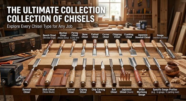
2.1 Introduction
A chisel is a hand cutting tool used for cutting, chipping, grooving, removing excess metal, and shaping materials by applying impact force with a hammer.
Chisels used in workshops are generally made from high-carbon steel or alloy tool steel. The cutting edge is hardened and tempered to withstand repeated impact and cutting action.
The selection of a chisel depends on the material, type of operation, shape of the required cut, and accessibility of the work area.
2.2 Main Parts of a Chisel
A typical hand chisel consists of the following parts:
Head
The head is the portion struck by a hammer. It is generally kept strong enough to withstand repeated blows.
Body or Shank
The body is the main portion of the chisel extending between the head and cutting edge.
Cutting Edge
The cutting edge is the sharpened portion that performs the cutting or chipping operation.
Cutting End
The cutting end is formed according to the particular type and application of the chisel.
2.3 Classification of Chisels
Workshop chisels can be classified according to their shape and application.
The important types include:
Flat Chisel
Cape Chisel
Cross-Cut Chisel
Diamond-Point Chisel
Round-Nose Chisel
Side Chisel
Cold Chisel
Hot Chisel
Brick Chisel
Mason’s Chisel
2.4 Flat Chisel
A flat chisel has a broad, flat cutting edge. It is one of the most commonly used chisels in fitting and general metalworking.
Features
Broad cutting edge
Flat cutting surface
Suitable for removing relatively large amounts of material
Available in different sizes
Uses
Used for general chipping operations.
Used for cutting metal sheets and bars.
Used for removing excess metal.
Used for cutting rivet heads.
Used for removing unwanted material from castings.
Used for general fitting work.
The broad cutting edge makes the flat chisel suitable for general-purpose metal cutting and chipping.
2.5 Cape Chisel
A cape chisel has a narrow, wedge-shaped cutting edge. It is used where a narrow cut or groove is required.
Features
Narrow cutting edge
Wedge-shaped point
Suitable for concentrated cutting action
Uses
Used for cutting narrow grooves.
Used for cutting keyways.
Used for making slots.
Used for cutting narrow channels.
Used for starting larger grooves.
Used for removing material from confined areas.
Cape chisels are particularly useful where a narrow and controlled cut is required.
2.6 Cross-Cut Chisel
A cross-cut chisel has a narrow cutting edge that is wider than the body in the cutting region. It is used primarily for producing grooves and channels.
Features
Narrow cutting edge
Wedge-shaped cutting portion
Suitable for narrow grooves
Uses
Used for cutting grooves.
Used for cutting keyways.
Used for making narrow channels.
Used for removing material from restricted areas.
Used for cutting slots in metal components.
2.7 Diamond-Point Chisel
A diamond-point chisel has a cutting end with a diamond-shaped cross-section.
Features
Diamond-shaped cutting end
Pointed cutting profile
Suitable for V-shaped grooves and special cuts
Uses
Used for cutting V-grooves.
Used for cutting narrow angular grooves.
Used for removing material from corners.
Used for making grooves in metal surfaces.
Used for working in confined locations.
The pointed profile allows the chisel to reach areas where a broad flat chisel cannot work effectively.
2.8 Round-Nose Chisel
A round-nose chisel has a rounded or semicircular cutting edge.
Features
Rounded cutting edge
Suitable for producing curved grooves
Designed for controlled material removal
Uses
Used for cutting oil grooves.
Used for making semicircular grooves.
Used for producing curved channels.
Used for removing material from curved surfaces.
Used in special fitting operations.
2.9 Side Chisel
A side chisel has a cutting edge designed for cutting grooves or slots from the side.
Features
Specially shaped cutting end
Suitable for side cutting
Useful in restricted areas
Uses
Used for cutting narrow slots.
Used for cutting grooves from the side.
Used for removing material from confined locations.
Used for special fitting operations.
2.10 Cold Chisel
A cold chisel is a general-purpose metalworking chisel used for cutting and chipping metal without heating the workpiece.
Features
Made from hardened and tempered tool steel.
Has a suitable wedge-shaped cutting edge.
Designed to withstand hammer blows.
Available in several shapes and sizes.
Uses
Used for cutting cold metal.
Used for removing excess metal.
Used for cutting bolts and rivets.
Used for removing welds and unwanted material.
Used for chipping castings.
Used in fitting and maintenance work.
Flat, cape, diamond-point, and round-nose chisels are commonly used forms of cold chisels for different operations.
2.11 Hot Chisel
A hot chisel is used for cutting and shaping metal while it is heated to a high temperature.
Features
Designed for hot metalworking.
Cutting edge is suitable for cutting heated metal.
Used primarily in forging operations.
Uses
Used for cutting heated metal bars.
Used for hot forging operations.
Used for cutting heated rods and sections.
Used for separating heated metal pieces.
Used for preparing metal stock during forging.
A hot chisel is used with heated metal, whereas a cold chisel is generally used on metal at normal temperature.
2.12 Brick Chisel
A brick chisel is a broad, strong chisel designed primarily for cutting and splitting bricks and similar masonry materials.
Features
Broad cutting edge
Strong construction
Suitable for masonry applications
Uses
Used for cutting bricks.
Used for splitting masonry materials.
Used for removing sections of brickwork.
Used for light masonry repair work.
2.13 Mason’s Chisel
A mason’s chisel is designed for cutting, shaping, and removing masonry materials such as brick, stone, and concrete.
Features
Strong cutting edge
Suitable for impact work
Available in different shapes for masonry applications
Uses
Used for cutting stone.
Used for cutting bricks.
Used for removing mortar.
Used for making grooves in masonry.
Used for demolition and repair work.
Used for shaping masonry surfaces.
2.14 Chisel Selection
The selection of a chisel depends on:
Type of material being cut
Thickness of the material
Shape of the required cut
Width and depth of the groove
Accessibility of the work area
Nature of the operation
Required cutting accuracy
For example, a flat chisel is suitable for general chipping, while a cape or cross-cut chisel is preferred for narrow grooves and slots.
2.15 Important Workshop Practices for Chisels
A chisel should be selected according to the job and kept properly sharpened. The cutting edge should be free from cracks and excessive damage.
During repeated hammering, the head of a chisel can develop a mushroomed shape. Such a condition can be hazardous because pieces of metal may break away during striking. Therefore, damaged or mushroomed chisel heads should be properly maintained or replaced.
The workpiece should also be securely held before beginning a cutting or chipping operation.
2.16 Summary of Chisel Types
| Type of Chisel | Main Uses |
| Flat Chisel | General cutting and chipping |
| Cape Chisel | Narrow grooves, slots and keyways |
| Cross-Cut Chisel | Grooves and narrow channels |
| Diamond-Point Chisel | V-grooves and angular cuts |
| Round-Nose Chisel | Curved and semicircular grooves |
| Side Chisel | Side cutting and restricted areas |
| Cold Chisel | Cutting and chipping cold metal |
| Hot Chisel | Cutting heated metal during forging |
| Brick Chisel | Cutting and splitting bricks |
| Mason’s Chisel | Cutting and shaping masonry |
FILES
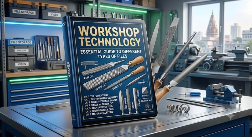
3.1 Introduction
A file is a multi-point cutting tool used to remove a small amount of material from a workpiece by rubbing its cutting teeth against the surface.
Files are widely used in fitting, bench work, toolmaking, fabrication, and maintenance operations. They are mainly used for removing excess material, producing the required shape and size, smoothing surfaces, and finishing edges.
A file consists of a hardened steel body provided with a series of cutting teeth. The file is generally operated by moving it over the workpiece with suitable pressure.
3.2 Main Parts of a File
A typical file consists of the following parts:
Point
The point is the extreme end of the file opposite the handle.
Face
The face is the broad surface containing the cutting teeth.
Edge
The edge is the narrow longitudinal surface of the file. In some files, the edge may also contain cutting teeth.
Heel
The heel is the portion of the file near the tang where the teeth generally terminate.
Tang
The tang is the tapered portion used for fitting the handle.
Shoulder
The shoulder is the portion between the body of the file and the tang.
Handle
The handle provides a safe and comfortable grip during filing operations.
3.3 Classification of Files
Files can be classified according to:
- Shape
- Cut of teeth
- Grade or coarseness
- Length
- Special application
3.4 Types of Files According to Shape
3.4.1 Flat File
A flat file has a rectangular cross-section and parallel or slightly tapered sides.
Features
Broad flat face
Rectangular cross-section
Suitable for general-purpose filing
Uses
Used for filing flat surfaces.
Used for reducing the size of metal components.
Used for finishing flat surfaces.
Used for removing burrs.
Used for general fitting work.
3.4.2 Hand File
A hand file is similar to a flat file but generally has a safe edge on one side.
Features
Rectangular cross-section
One edge may be uncut
Suitable for filing surfaces close to another surface
Uses
Used for general fitting work.
Used for filing flat surfaces.
Used for finishing edges.
Used where an adjacent surface must not be cut.
Used for producing accurate dimensions.
3.4.3 Square File
A square file has a square cross-section and is generally tapered toward the point.
Uses
Used for filing square holes.
Used for enlarging rectangular openings.
Used for producing square grooves.
Used for filing keyways.
Used for internal corners.
3.4.4 Round File
A round file has a circular cross-section and is also commonly called a round file or rat-tail file when used in a tapered form.
Uses
Used for enlarging round holes.
Used for filing curved surfaces.
Used for producing semicircular grooves.
Used for finishing concave surfaces.
Used for filing internal radii.
3.4.5 Half-Round File
A half-round file has one flat face and one curved face.
Uses
Used for filing concave surfaces.
Used for filing flat surfaces.
Used for producing curved profiles.
Used for internal curved surfaces.
Used for general fitting work.
Its two different surfaces make it suitable for both flat and curved filing operations.
3.4.6 Triangular File
A triangular file has a triangular cross-section.
It is also commonly known as a three-square file.
Uses
Used for filing V-shaped grooves.
Used for sharpening saw teeth.
Used for filing angular grooves.
Used for producing internal angles.
Used for finishing triangular openings.
3.4.7 Knife-Edge File
A knife-edge file has a very thin wedge-shaped cross-section.
Uses
Used for filing narrow slots.
Used for producing sharp internal angles.
Used for filing narrow grooves.
Used for working in confined spaces.
Used for precision fitting operations.
3.4.8 Pillar File
A pillar file is a relatively narrow rectangular file with parallel sides.
Uses
Used for precision filing.
Used for filing narrow flat surfaces.
Used for producing slots.
Used for toolmaking and fitting operations.
Used where greater control is required.
3.4.9 Warding File
A warding file is a thin, narrow file designed for working in narrow slots and restricted spaces.
Uses
Used for filing narrow slots.
Used in lock and key work.
Used for precision fitting.
Used for working in confined areas.
3.5 Types of Files According to Cut
The cut of a file refers to the arrangement and form of its teeth.
3.5.1 Single-Cut File
A single-cut file has one series of parallel teeth across its surface.
Features
The teeth are arranged in a single direction.
Uses
Used for light material removal.
Used for finishing surfaces.
Used for sharpening cutting edges.
Used where a relatively smooth finish is required.
Used for soft and relatively ductile materials.
3.5.2 Double-Cut File
A double-cut file has two sets of intersecting teeth.
Features
The first set of teeth is known as the overcut and the second set crosses it.
Uses
Used for faster material removal.
Used for rough and general-purpose filing.
Used for reducing large amounts of material.
Used for shaping metal components.
Used in general fitting work.
Double-cut files generally remove material faster than single-cut files.
3.5.3 Rasp-Cut File
A rasp-cut file has individual, raised teeth formed by a special cutting process.
Uses
Used mainly on wood.
Used on soft materials.
Used for shaping and removing material from softer workpieces.
Used in woodworking and related applications.
3.5.4 Curved-Cut File
A curved-cut file has curved rows of teeth across its surface.
Uses
Used for rapid material removal.
Used for filing soft materials.
Used for aluminium and similar materials.
Used where clogging of the file needs to be reduced.
Used for producing a relatively smooth finish.
3.6 Types of Files According to Grade
The grade of a file indicates the relative coarseness or fineness of its teeth.
The common grades are:
- Rough
- Bastard
- Second Cut
- Smooth
- Dead Smooth
3.6.1 Rough File
A rough file has relatively large and coarse teeth.
Uses
Used for rapid removal of material.
Used for rough shaping.
Used when a large amount of material has to be removed.
Used on relatively soft materials.
It is not normally used when a fine surface finish is required.
3.6.2 Bastard File
A bastard file has teeth finer than a rough file but coarser than a second-cut file.
Uses
Used for general-purpose filing.
Used for removing moderate amounts of material.
Used for shaping workpieces.
Used for general fitting operations.
3.6.3 Second-Cut File
A second-cut file has finer teeth than a bastard file.
Uses
Used for intermediate filing.
Used after rough filing.
Used for improving surface finish.
Used for bringing a workpiece closer to its final size.
3.6.4 Smooth File
A smooth file has relatively fine teeth.
Uses
Used for finishing surfaces.
Used for accurate fitting.
Used for removing small amounts of material.
Used where a smoother surface is required.
3.6.5 Dead-Smooth File
A dead-smooth file has very fine teeth.
Uses
Used for fine finishing.
Used for precision fitting.
Used for producing a smooth surface.
Used for removing very small amounts of material.
3.7 Types of Files According to Application
Needle Files
Needle files are small files with relatively fine teeth and are usually supplied in sets of different shapes.
Common Types
Flat
Square
Round
Half-Round
Triangular
Knife-Edge
Uses
Used for precision filing.
Used for small components.
Used for dies and moulds.
Used for toolmaking.
Used for intricate and delicate work.
Swiss Pattern Files
Swiss pattern files are precision files having fine teeth and are used for detailed and accurate filing operations.
Uses
Used for precision engineering.
Used for tool and die work.
Used for fine finishing.
Used for small and intricate components.
3.8 File Selection
The correct file should be selected according to:
Shape of the workpiece
Amount of material to be removed
Required surface finish
Required accuracy
Material being filed
Accessibility of the surface
Type of filing operation
For example, a flat file is suitable for flat surfaces, a round file for curved surfaces and holes, and a triangular file for V-grooves and saw-tooth work.
3.9 Proper Use of a File
During filing, the workpiece should be held securely in a suitable vice or fixture.
The file should be fitted with a proper handle when it has a tang. The operator should apply suitable pressure during the forward cutting stroke and avoid excessive pressure during the return stroke.
The file should be kept clean so that material particles do not clog the teeth.
Files should not be used as hammers, levers, or pry tools because they are designed specifically for cutting and finishing operations.
3.10 File Card
A file card is a cleaning tool fitted with short wire bristles.
Uses
Used for cleaning clogged file teeth.
Used for removing metal particles from the file.
Used for maintaining the cutting effectiveness of the file.
3.11 Summary of File Types
| Classification | Type |
| According to Shape | Flat File |
| Hand File | |
| Square File | |
| Round File | |
| Half-Round File | |
| Triangular File | |
| Knife-Edge File | |
| Pillar File | |
| Warding File | |
| According to Cut | Single-Cut File |
| Double-Cut File | |
| Rasp-Cut File | |
| Curved-Cut File | |
| According to Grade | Rough |
| Bastard | |
| Second Cut | |
| Smooth | |
| Dead Smooth | |
| Special Files | Needle File |
| Swiss Pattern File |
HACKSAWS
4.1 Introduction
A hacksaw is a hand or power-operated cutting tool used for cutting metal, plastic, pipes, rods, bars, sheets, and other materials.
A hacksaw consists mainly of a frame and a replaceable toothed blade. The blade is fitted under tension in the frame, and cutting takes place when the teeth move against the workpiece.
Hacksaws are widely used in fitting, maintenance, fabrication, plumbing, machine shops, and general workshop operations.
4.2 Main Parts of a Hand Hacksaw
A typical hand hacksaw consists of:
Frame
The frame holds the blade and maintains the required blade tension.
Handle
The handle provides a firm grip and allows the operator to move the saw safely.
Blade
The blade is the cutting member and contains a series of teeth along one edge.
Blade Tensioning Screw
It is used to adjust the tension of the blade.
Wing Nut
The wing nut or tensioning mechanism helps secure and tension the blade.
Blade Pins
The pins or pegs at the ends of the frame hold the blade in position.
4.3 Types of Hacksaws
Hacksaws can be classified according to their construction, operation, and application.
The important types are:
- Hand Hacksaw
- Junior Hacksaw
- Fixed Frame Hacksaw
- Adjustable Frame Hacksaw
- Power Hacksaw
- Electric Hacksaw
- Reciprocating Hacksaw
4.4 Hand Hacksaw
A hand hacksaw is a manually operated saw consisting of a frame and a removable toothed blade.
Features
Manually operated
Replaceable blade
Blade fitted under tension
Available with different blade lengths and tooth pitches
Uses
Used for cutting metal bars.
Used for cutting rods and pipes.
Used for cutting bolts and screws.
Used for cutting small sections and strips.
Used for general fitting work.
Used for maintenance and repair operations.
The hand hacksaw is one of the most commonly used cutting tools in a general workshop.
4.5 Junior Hacksaw
A junior hacksaw is a small and lightweight hacksaw designed for light cutting operations.
Features
Small frame
Narrow blade
Lightweight construction
Suitable for small and delicate work
Uses
Used for cutting small metal sections.
Used for cutting thin rods and tubes.
Used for cutting small plastic components.
Used for light maintenance work.
Used where access is restricted.
4.6 Fixed Frame Hacksaw
A fixed frame hacksaw has a frame of fixed dimensions designed to accommodate a particular blade length.
Features
Rigid frame
Simple construction
Blade held securely
Suitable for regular cutting work
Uses
Used for general workshop cutting.
Used for cutting rods, bars and pipes.
Used for routine fitting operations.
Used for maintenance work.
4.7 Adjustable Frame Hacksaw
An adjustable frame hacksaw has a frame that can be adjusted to accommodate blades of different lengths.
Features
Adjustable frame
Can accommodate different blade sizes
More versatile than a fixed frame
Uses
Used for general-purpose cutting.
Used where different blade lengths are required.
Used in maintenance workshops.
Used for cutting materials of different sizes.
4.8 Power Hacksaw
A power hacksaw is a machine-operated hacksaw in which the blade is moved mechanically rather than manually.
Features
Mechanically operated
Suitable for repetitive cutting
Can cut larger sections than a hand hacksaw
Provides more consistent cutting action
Uses
Used for cutting metal bars.
Used for cutting pipes.
Used for cutting rods and structural sections.
Used for production and workshop cutting.
Used where repeated cutting operations are required.
4.9 Electric Hacksaw
An electric hacksaw uses an electric motor to provide the cutting motion.
Features
Powered by an electric motor
Reduces manual effort
Suitable for repeated cutting operations
Provides relatively consistent cutting action
Uses
Used for cutting metal sections.
Used for workshop maintenance.
Used for fabrication work.
Used for repeated cutting operations.
Used where manual hacksawing would require excessive effort.
4.10 Reciprocating Hacksaw
A reciprocating hacksaw uses a back-and-forth movement of the blade to perform the cutting operation.
Features
Reciprocating blade motion
Mechanically powered
Suitable for cutting relatively large sections
Used for continuous or repeated cutting operations
Uses
Used for cutting metal bars.
Used for cutting pipes and sections.
Used in fabrication shops.
Used in machine and maintenance workshops.
4.11 Hacksaw Blades
The hacksaw blade is the actual cutting element of a hacksaw.
Hacksaw blades are generally made from high-carbon steel, high-speed steel, or other suitable tool materials, depending on the application.
They are available with different tooth pitches.
4.12 Types of Hacksaw Blades According to Tooth Pitch
The common tooth pitches include:
Coarse
Medium
Fine
Very Fine
The selection depends mainly on the thickness and type of material being cut.
Coarse-Tooth Blade
Used for:
Thick sections
Soft materials
Rapid material removal
Medium-Tooth Blade
Used for:
General-purpose cutting
Medium-thickness materials
General workshop operations
Fine-Tooth Blade
Used for:
Thin sections
Thin sheets
Small tubes
Small components
Very Fine-Tooth Blade
Used for:
Very thin materials
Fine cutting operations
Small and delicate sections
4.13 Hacksaw Blade Tooth Arrangement
Hacksaw blades may also differ in the arrangement and design of their teeth.
Regular Tooth Blade
The teeth are arranged in a conventional uniform pattern.
Uses:
General-purpose cutting
Common workshop materials
Variable-Tooth Blade
The tooth spacing varies along the blade.
Uses:
Reducing vibration
Cutting difficult sections
Cutting materials where smoother cutting action is desirable
4.14 Selection of Hacksaw Blade
The correct blade should be selected according to:
Material being cut
Thickness of material
Shape of the workpiece
Required cutting speed
Type of cutting operation
Accessibility of the workpiece
A general rule is that thin materials require finer teeth, while thicker materials can generally be cut with coarser teeth.
4.15 Proper Use of a Hacksaw
The workpiece should be firmly held in a vice or suitable fixture before cutting.
The blade should be fitted with its teeth pointing in the forward cutting direction for a conventional hand hacksaw.
The blade should be tensioned properly. Excessive tension can damage the blade or frame, while insufficient tension can cause poor cutting and blade bending.
During cutting, the operator should use controlled, steady strokes and avoid excessive force.
4.16 Applications of Hacksaws
Hacksaws are commonly used for:
Cutting rods
Cutting pipes
Cutting metal bars
Cutting bolts
Cutting screws
Cutting strips
Cutting tubes
Cutting small structural sections
General fitting work
Maintenance and repair work
Fabrication operations
4.17 Summary of Hacksaw Types
| Type | Main Uses |
| Hand Hacksaw | General manual cutting |
| Junior Hacksaw | Light and small cutting work |
| Fixed Frame Hacksaw | Routine workshop cutting |
| Adjustable Frame Hacksaw | Cutting with different blade lengths |
| Power Hacksaw | Mechanically powered heavy/repetitive cutting |
| Electric Hacksaw | Motor-powered cutting |
| Reciprocating Hacksaw | Repeated cutting of metal sections |
SNIPS & SHEARS
5.1 Introduction
Snips and shears are cutting tools used mainly for cutting sheet metal, thin metal plates, wires, strips, and other thin materials.
They work on the principle of shearing, in which two cutting edges move past each other and separate the material.
The selection of snips or shears depends on the thickness, shape, and type of material, as well as the required cutting direction.
5.2 SNIPS
A snip is a hand-operated cutting tool having two sharp cutting blades joined at a pivot. It is mainly used for cutting thin sheets and light materials.
Snips are particularly useful where the material has to be cut manually along straight or curved lines.
5.3 Types of Snips
The important types of snips are:
- Straight Snips
- Curved Snips
- Duckbill Snips
- Combination Snips
- Aviation Snips
- Offset Snips
- Tinner’s Snips
5.4 Straight Snips
Straight snips have relatively straight cutting blades.
Features
Straight cutting edges
Designed mainly for straight cuts
Hand-operated
Uses
Used for cutting sheet metal in straight lines.
Used for trimming sheet-metal edges.
Used for cutting thin metal strips.
Used for general sheet-metal work.
5.5 Curved Snips
Curved snips have blades designed to follow curved cutting paths.
Features
Curved or specially shaped cutting edges
Suitable for curved profiles
Uses
Used for cutting curved lines.
Used for cutting circular or irregular shapes.
Used for trimming curved sheet-metal edges.
Used in sheet-metal fabrication.
5.6 Duckbill Snips
Duckbill snips have blades with a distinctive broad, curved shape resembling a duck’s bill.
Features
Broad curved blades
Suitable for controlled cutting of sheet material
Provides better access for certain curved cuts
Uses
Used for cutting curves in sheet metal.
Used for trimming sheet-metal components.
Used for cutting irregular shapes.
Used in fabrication and sheet-metal work.
5.7 Combination Snips
Combination snips are general-purpose hand snips designed for both straight and curved cutting.
Uses
Used for straight cuts.
Used for curved cuts.
Used for trimming sheet metal.
Used for general sheet-metal fabrication.
5.8 Aviation Snips
Aviation snips are specially designed hand-operated snips commonly used for cutting sheet metal.
They are generally available in different configurations for different cutting directions.
Types of Aviation Snips
Straight-Cut Aviation Snips
Usually identified as snips intended primarily for straight cutting.
Uses:
Cutting straight lines in sheet metal.
Trimming sheet edges.
General sheet-metal work.
Left-Cut Aviation Snips
Designed to make left-hand or left-direction curved cuts.
Uses:
Cutting curves toward the left.
Cutting irregular sheet-metal profiles.
Trimming curved edges.
Right-Cut Aviation Snips
Designed to make right-hand or right-direction curved cuts.
Uses:
Cutting curves toward the right.
Cutting irregular profiles.
Trimming sheet-metal edges.
The different blade configurations make aviation snips more suitable for controlled curved cutting than ordinary straight snips.
5.9 Offset Snips
Offset snips have handles or blades arranged so that the operator’s hand is positioned away from the sheet being cut.
Features
Offset blade arrangement
Improved hand clearance
Suitable for longer cuts
Uses
Used for cutting sheet metal.
Used for making longer cuts.
Used where hand clearance is required.
Used for cutting curved and straight profiles depending on design.
5.10 Tinner’s Snips
Tinner’s snips are strong hand-operated cutting tools traditionally used by tinsmiths for cutting thin sheet metal.
Types
Straight Pattern
Curved Pattern
Combination Pattern
Uses
Used for cutting thin sheet metal.
Used for trimming metal sheets.
Used for fabrication work.
Used for making straight and curved cuts.
5.11 SHEARS
A shear is a cutting tool in which two cutting edges pass one another to cut sheet material. Shears may be operated manually, mechanically, or by power.
Compared with ordinary snips, shears are generally used when greater cutting capacity, improved control, or repeated cutting is required.
5.12 Types of Shears
Important workshop shears include:
- Hand Shears
- Bench Shears
- Lever Shears
- Throatless Shears
- Guillotine Shears
- Power Shears
- Foot-Operated Shears
- Pneumatic Shears
5.13 Hand Shears
Hand shears are manually operated cutting tools used for thin sheet material.
Uses
Used for cutting sheet metal.
Used for trimming edges.
Used for cutting small sheet-metal components.
Used for general fabrication work.
5.14 Bench Shears
Bench shears are mounted on a bench or worktable and provide greater stability than ordinary hand snips.
Features
Fixed to a bench
Lever-operated
Provides better cutting control
Uses
Used for cutting sheet metal.
Used for trimming sheets.
Used for cutting strips.
Used for repetitive workshop operations.
5.15 Lever Shears
Lever shears use a lever mechanism to increase the cutting force applied by the operator.
Features
Long operating lever
Greater mechanical advantage
Suitable for thicker sheet material than ordinary hand snips
Uses
Used for cutting sheet metal.
Used for cutting metal strips.
Used for trimming larger sheets.
Used for repeated cutting operations.
5.16 Throatless Shears
A throatless shear is designed so that the workpiece can move freely around the cutting area without being restricted by a fixed throat.
Features
Open working area
Allows the sheet to be moved in different directions
Suitable for irregular shapes
Uses
Used for cutting irregular shapes.
Used for curved profiles.
Used for circular patterns.
Used for sheet-metal fabrication.
5.17 Guillotine Shears
A guillotine shear uses a blade arrangement in which the cutting action takes place across the width of the sheet.
Features
Straight cutting blade
Suitable for accurate straight cuts
Available in manual and powered forms
Uses
Used for cutting large sheets.
Used for making straight cuts.
Used for cutting sheet-metal strips.
Used in fabrication and production work.
5.18 Power Shears
Power shears use an electric motor or another power source to produce the cutting action.
Features
Power operated
Reduces manual effort
Suitable for repetitive cutting
Provides faster cutting than hand-operated tools
Uses
Used for cutting sheet metal.
Used for fabrication work.
Used for repeated production cutting.
Used for trimming metal sheets.
5.19 Foot-Operated Shears
Foot-operated shears use a foot pedal or treadle to operate the cutting mechanism.
Features
Operated by foot
Hands remain available for controlling the workpiece
Suitable for sheet-metal work
Uses
Used for cutting sheet metal.
Used for straight cutting.
Used for repeated fabrication work.
Used where both hands are needed to control the sheet.
5.20 Pneumatic Shears
Pneumatic shears are operated using compressed air.
Features
Powered by compressed air
Suitable for repeated cutting
Reduces operator effort
Uses
Used for sheet-metal fabrication.
Used for repetitive cutting operations.
Used in industrial workshops.
Used where compressed-air equipment is available.
5.21 Selection of Snips and Shears
The correct tool should be selected according to:
Thickness of sheet
Type of material
Straight or curved cut
Size of workpiece
Required accuracy
Frequency of cutting
Available operating space
Snips are generally preferred for light manual cutting, while shears are selected when greater cutting capacity, stability, or production efficiency is required.
5.22 Summary
| Tool / Type | Main Use |
| Straight Snips | Straight sheet-metal cuts |
| Curved Snips | Curved cuts |
| Duckbill Snips | Curved and irregular cuts |
| Combination Snips | Straight and curved cuts |
| Aviation Snips | Controlled straight and curved cuts |
| Offset Snips | Cutting with improved hand clearance |
| Tinner’s Snips | General sheet-metal cutting |
| Hand Shears | Light manual sheet cutting |
| Bench Shears | Stable bench-mounted cutting |
| Lever Shears | Higher-force sheet cutting |
| Throatless Shears | Irregular and curved profiles |
| Guillotine Shears | Straight sheet cutting |
| Power Shears | Fast and repeated cutting |
| Foot-Operated Shears | Controlled sheet cutting |
| Pneumatic Shears | Powered industrial cutting |
PLIERS
6.1 Introduction
Pliers are hand-operated workshop tools used mainly for gripping, holding, bending, twisting, cutting, and manipulating wires, small components, rods, and other materials.
They consist generally of two metal levers joined at a pivot. The jaws are operated by opening and closing the handles. The lever action multiplies the force applied by the operator, allowing a relatively small hand force to produce a greater gripping or cutting force at the jaws.
Pliers are widely used in fitting, electrical work, mechanical maintenance, automotive repair, sheet-metal work, fabrication, assembly, and general workshop operations.
6.2 Construction and Main Parts of Pliers
A typical pair of pliers consists of the following parts:
1. Jaws
The jaws are the working portions of the pliers. They grip, hold, bend, or cut the workpiece depending on the type of pliers.
2. Pivot
The pivot connects the two halves of the pliers and allows them to rotate relative to each other.
3. Handles
Handles provide the means of applying hand force. They may have insulated or non-slip coverings for improved grip and operator comfort.
4. Cutting Edges
Certain pliers are provided with hardened cutting edges for cutting wires, cables, pins, and similar materials.
5. Nose
The nose is the forward portion of the pliers containing the jaws. Its shape varies according to the intended application.
6.3 Working Principle of Pliers
Pliers operate according to the principle of the lever.
The pivot acts as the fulcrum. When force is applied to the handles, the jaws move in the opposite direction and exert a gripping or cutting force on the workpiece.
The mechanical advantage depends on the relative distances between:
The hand force and the pivot
The working jaws or cutting edges and the pivot
A longer handle generally allows greater force to be produced at the jaws, while the jaw shape determines the type of operation that can be performed.
6.4 Types of Pliers
Important workshop pliers include:
- Combination Pliers
- Long-Nose Pliers
- Needle-Nose Pliers
- Round-Nose Pliers
- Flat-Nose Pliers
- Bent-Nose Pliers
- Side-Cutting Pliers
- Diagonal Cutting Pliers
- End-Cutting Pliers
- Slip-Joint Pliers
- Groove-Joint Pliers
- Water-Pump Pliers
- Locking Pliers
- Linesman’s Pliers
- Circlip Pliers
- Internal Circlip Pliers
- External Circlip Pliers
- Snap-Ring Pliers
- Retaining-Ring Pliers
6.5 Combination Pliers
Definition
Combination pliers are general-purpose pliers designed for gripping, holding, bending, twisting, and cutting wires.
Features
They normally have:
Serrated gripping jaws
A cutting section near the pivot
Strong handles
A central pivot joint
The jaws may include a relatively flat gripping area and a cutting edge.
Uses
Combination pliers are used for:
Holding wires
Bending wires
Twisting wires
Cutting small and medium wires
Gripping nuts and small components
General maintenance work
Electrical and mechanical workshop operations
They are one of the most commonly used general-purpose pliers.
6.6 Long-Nose Pliers
Definition
Long-nose pliers have long, narrow jaws designed for reaching and manipulating components in confined spaces.
Features
The jaws are considerably longer and narrower than those of combination pliers.
Uses
They are used for:
Holding small components
Bending wires
Positioning wires
Reaching into narrow spaces
Electrical assembly
Instrument work
Removing or positioning small parts
They are particularly useful where ordinary pliers cannot reach.
6.7 Needle-Nose Pliers
Definition
Needle-nose pliers are precision gripping pliers having very narrow, tapered jaws.
Features
Their long tapered nose allows access to small and restricted areas.
Uses
They are used for:
Holding thin wires
Bending small wires
Forming wire loops
Handling small components
Electrical work
Electronic assembly
Precision mechanical work
They are especially suitable for delicate manipulation rather than heavy gripping.
6.8 Round-Nose Pliers
Definition
Round-nose pliers have smooth, rounded jaws used mainly for forming and bending wire into curves and loops.
Features
The jaws are generally tapered and circular in cross-section.
Uses
They are used for:
Making wire loops
Forming circular bends
Producing curved wire shapes
Electrical wiring
Jewellery and fine wire work
Small component forming
They are selected when smooth curved bends are required.
6.9 Flat-Nose Pliers
Definition
Flat-nose pliers have broad, flat jaws used for gripping, bending, and positioning small components.
Features
Their jaws provide relatively large flat contact surfaces.
Uses
They are used for:
Holding flat components
Bending sheet material
Straightening wires
Forming wires
Positioning components
General assembly work
They are useful where a firm, controlled grip is required without using serrated jaws.
6.10 Bent-Nose Pliers
Definition
Bent-nose pliers have jaws that are angled or curved relative to the handles.
Features
The angled nose improves visibility and access in restricted locations.
Uses
They are used for:
Reaching around obstacles
Holding small components
Bending wires
Positioning parts
Electrical work
Assembly and maintenance operations
6.11 Side-Cutting Pliers
Definition
Side-cutting pliers are pliers equipped with cutting edges positioned on the side of the jaws.
Features
They are designed primarily for cutting rather than heavy gripping.
Uses
They are used for:
Cutting wires
Cutting small cables
Cutting pins and leads
Electrical installation
Assembly work
General maintenance
The correct cutting capacity must always be considered before cutting a material.
6.12 Diagonal Cutting Pliers
Definition
Diagonal cutting pliers have cutting edges arranged diagonally to the handles and are designed primarily for cutting wire.
Features
The angled cutting edges allow the tool to cut close to a surface in many applications.
Uses
They are used for:
Cutting electrical wires
Cutting component leads
Cutting small pins
Trimming wire ends
Electrical and electronic work
General workshop maintenance
They should not be used to cut materials harder than their specified capacity.
6.13 End-Cutting Pliers
Definition
End-cutting pliers have cutting edges located at the end of the jaws.
Features
The cutting edges meet at the end of the tool, allowing cutting close to the surface of the workpiece.
Uses
They are used for:
Cutting nails
Cutting wire
Removing pins
Cutting protruding material
Trimming wire close to a surface
Construction and maintenance work
They are particularly useful when a flush or near-surface cut is required.
6.14 Slip-Joint Pliers
Definition
Slip-joint pliers have an adjustable pivot that allows the jaws to be set at different openings.
Features
The pivot can be moved between different positions to accommodate different sizes of workpieces.
Uses
They are used for:
Gripping pipes
Holding nuts and fittings
General maintenance
Holding irregular components
Plumbing operations
Mechanical repair
They provide greater versatility than fixed-joint gripping pliers.
6.15 Groove-Joint Pliers
Definition
Groove-joint pliers are adjustable pliers in which the pivot mechanism moves through a series of grooves or positions.
Features
They provide a wide range of jaw openings while maintaining useful gripping capability.
Uses
They are used for:
Holding pipes
Gripping large fittings
Plumbing work
Mechanical maintenance
Holding irregularly shaped components
General repair work
6.16 Water-Pump Pliers
Definition
Water-pump pliers are adjustable gripping pliers designed for gripping objects of different sizes, particularly pipes and fittings.
Features
They have:
Long handles
Adjustable jaw positions
Serrated jaws
Strong gripping capability
Uses
They are commonly used for:
Pipes
Plumbing fittings
Nuts and couplings
Mechanical maintenance
General workshop repair
They are also commonly known as groove-joint or tongue-and-groove pliers depending on their construction.
6.17 Locking Pliers
Definition
Locking pliers are pliers that can be locked onto a workpiece and maintain gripping force without continuous hand pressure.
Features
They generally include:
Adjustable screw mechanism
Locking mechanism
Serrated jaws
Release lever
Uses
They are used for:
Holding workpieces securely
Clamping components
Holding parts during welding
Removing damaged fasteners
Temporary clamping
Mechanical maintenance
They are particularly useful when the operator needs to keep both hands available.
6.18 Linesman’s Pliers
Definition
Linesman’s pliers are heavy-duty pliers designed for gripping, twisting, and cutting electrical conductors and wires.
Features
They generally have:
Strong serrated jaws
Hardened cutting edges
Robust construction
Long handles for increased leverage
Uses
They are used for:
Electrical wiring
Cutting wires
Twisting conductors
Pulling wires
Gripping cables
General electrical maintenance
6.19 Circlip Pliers
Definition
Circlip pliers are specialized pliers used for installing and removing circlips or retaining rings.
Features
Their tips fit into the holes provided in a circlip.
Depending on their design, the pliers may expand an external circlip or compress an internal circlip.
Uses
They are used for:
Removing circlips
Installing circlips
Servicing shafts
Servicing bearings
Automotive repair
Machinery maintenance
6.20 Internal Circlip Pliers
Definition
Internal circlip pliers are designed to remove and install circlips located inside a bore or housing.
Working Action
When the handles are operated, the jaws move in a direction that allows the internal retaining ring to be compressed for removal or installation.
Uses
They are used in:
Bearing housings
Gearboxes
Mechanical assemblies
Automotive components
Machinery maintenance
6.21 External Circlip Pliers
Definition
External circlip pliers are designed for circlips mounted on shafts or outside cylindrical components.
Working Action
The tips engage the holes of the external circlip and move the ring outward or inward as required for installation or removal.
Uses
They are used for:
Shafts
Bearings
Gear assemblies
Automotive components
Mechanical equipment
6.22 Snap-Ring Pliers
Definition
Snap-ring pliers are specialized tools for installing and removing snap rings used as retaining elements in mechanical assemblies.
Features
They are available in different forms depending on whether the ring is internal or external and whether straight or angled access is required.
Uses
They are used in:
Bearings
Shafts
Gearboxes
Automotive assemblies
Hydraulic and mechanical equipment
6.23 Retaining-Ring Pliers
Definition
Retaining-ring pliers are designed specifically for installing and removing retaining rings used to prevent components from moving axially.
Uses
They are used in:
Machinery
Automotive systems
Bearings
Gear assemblies
Pumps
Mechanical equipment
The pliers must match the retaining-ring design and size.
6.24 Selection of Pliers
The correct pliers should be selected according to the operation and workpiece.
Important factors include:
1. Type of Operation
Determine whether the tool is required for:
Gripping
Bending
Cutting
Clamping
Wire forming
Circlip removal
2. Material
Consider the material and hardness of the wire or component before cutting or gripping it.
3. Size of Workpiece
Adjustable pliers should be selected when the workpiece size varies considerably.
4. Accessibility
Long-nose, needle-nose, or bent-nose pliers are suitable for restricted areas.
5. Required Force
Heavy-duty pliers should be selected for high-force applications.
6. Precision
Fine work requires appropriately sized precision pliers with suitable jaw geometry.
6.25 Proper Use of Pliers
For safe and effective operation:
Select the correct type of pliers.
Use pliers of suitable size and capacity.
Keep the jaws clean.
Apply force smoothly.
Keep fingers away from the closing area.
Do not use ordinary pliers as a hammer.
Do not use cutting pliers for materials harder than their rated capacity.
Do not extend handles with pipes or other objects to increase leverage unless the tool is specifically designed for such use.
Do not use insulated handles as protection against electrical voltage unless the pliers are specifically rated and certified for that purpose.
Keep the pivot properly lubricated where appropriate.
Replace damaged or excessively worn pliers.
6.26 Maintenance of Pliers
Proper maintenance increases tool life and reliability.
Cleaning
Remove dirt, grease, metal particles, and other contaminants after use.
Lubrication
Apply suitable lubricant to the pivot when required.
Inspection
Check for:
Cracked handles
Damaged jaws
Worn cutting edges
Loose pivots
Corrosion
Damaged insulation
Storage
Store pliers in a dry location and protect them from excessive moisture and corrosion.
6.27 Applications of Pliers in Workshops
Pliers are used extensively in:
Fitting shops
Machine shops
Electrical workshops
Automobile workshops
Plumbing work
Sheet-metal work
Welding and fabrication
Maintenance departments
Assembly operations
Mechanical repair
Electronics and instrument work
6.28 Summary Table
| Type of Pliers | Main Feature | Principal Uses |
| Combination Pliers | General-purpose gripping and cutting | Holding, bending, cutting wires |
| Long-Nose Pliers | Long narrow jaws | Confined spaces, wire work |
| Needle-Nose Pliers | Very narrow tapered jaws | Precision gripping and forming |
| Round-Nose Pliers | Rounded jaws | Wire loops and curved bends |
| Flat-Nose Pliers | Flat jaws | Holding and bending |
| Bent-Nose Pliers | Angled jaws | Restricted access |
| Side-Cutting Pliers | Side cutting edges | Wire cutting |
| Diagonal Cutting Pliers | Diagonal cutting edges | Wire and lead cutting |
| End-Cutting Pliers | Cutting edges at end | Nails, pins, flush cutting |
| Slip-Joint Pliers | Adjustable pivot | General gripping |
| Groove-Joint Pliers | Multiple jaw positions | Pipes and fittings |
| Water-Pump Pliers | Wide adjustable grip | Plumbing and maintenance |
| Locking Pliers | Locking mechanism | Clamping and holding |
| Linesman’s Pliers | Heavy-duty construction | Electrical and wire work |
| Circlip Pliers | Special tips for circlips | Installing/removing circlips |
| Internal Circlip Pliers | For internal rings | Bore and housing assemblies |
| External Circlip Pliers | For external rings | Shafts and external assemblies |
| Snap-Ring Pliers | Snap-ring handling | Mechanical assemblies |
| Retaining-Ring Pliers | Retaining-ring handling | Bearings, shafts and machinery |
6.29 Conclusion
Pliers are essential workshop hand tools based on the lever principle. Different jaw shapes, cutting arrangements, adjustment mechanisms, and specialized tips allow them to perform a wide range of operations. Proper selection according to the material, size, accessibility, and required operation improves efficiency, accuracy, and safety in workshop practice.
SCREWDRIVERS
7.1 Introduction
A screwdriver is a hand tool used for tightening and loosening screws. It consists mainly of a handle, shank, and working tip or blade.
Screwdrivers are widely used in fitting, assembly, electrical work, automobile maintenance, machine repair, appliance servicing, and general workshop operations.
The correct screwdriver must be selected according to the type, size, and head design of the screw. Using an unsuitable screwdriver can damage both the screw head and the tool.
7.2 Construction of a Screwdriver
A typical screwdriver consists of the following main parts:
1. Handle
The handle is the portion held by the operator. It is commonly made from plastic, composite material, wood, or other suitable materials.
The handle provides:
Comfortable gripping
Torque transmission
Control during operation
Some handles are designed with textured or non-slip surfaces to improve grip.
2. Shank
The shank is the metal shaft connecting the handle to the working tip.
It is generally manufactured from hardened steel or alloy steel suitable for transmitting torque.
3. Tip or Blade
The tip engages with the screw head.
Its shape must correspond to the screw-head recess or slot.
4. Ferrule
Some screwdrivers have a ferrule between the handle and shank. It provides additional support and strength to the connection.
7.3 Working Principle of a Screwdriver
A screwdriver operates by converting the turning force applied to the handle into rotational motion of the screw.
When the operator rotates the handle:
- Torque is transmitted through the shank.
- The tip engages with the screw head.
- The screw rotates.
- The screw moves into or out of the threaded hole depending on the direction of rotation.
A properly fitting tip provides good contact with the screw head and reduces the possibility of slipping or damaging the recess.
7.4 Types of Screwdrivers
Important types of workshop screwdrivers include:
- Flat-Blade Screwdriver
- Slotted Screwdriver
- Phillips Screwdriver
- Pozidriv Screwdriver
- Torx Screwdriver
- Hex Screwdriver
- Robertson Screwdriver
- JIS Screwdriver
- Precision Screwdriver
- Stubby Screwdriver
- Offset Screwdriver
- Ratcheting Screwdriver
- Insulated Screwdriver
- Electrician’s Screwdriver
- Nut Driver
- Interchangeable-Bit Screwdriver
7.5 Flat-Blade Screwdriver
Definition
A flat-blade screwdriver has a flat, straight working tip designed to engage a screw having a straight slot.
Features
The tip is generally rectangular or blade-shaped.
The width and thickness of the tip must be appropriate for the screw slot.
Uses
It is used for:
Slotted screws
General assembly
Machine maintenance
Electrical equipment
Appliances
Workshop repair
7.6 Slotted Screwdriver
Definition
A slotted screwdriver is specifically designed for screws with a single straight slot across the head.
It is commonly considered the standard flat-tip screwdriver.
Uses
It is used for:
Slotted machine screws
Wood screws
Electrical terminals
General maintenance
Equipment assembly
Fitting work
The tip should fit the slot closely to prevent damage to the screw head.
7.7 Phillips Screwdriver
Definition
A Phillips screwdriver has a cross-shaped tip designed for Phillips-head screws.
Features
The tip has four primary driving surfaces arranged in a cross pattern.
Different sizes are available to match different screw-head sizes.
Uses
Phillips screwdrivers are commonly used in:
Machine assembly
Electrical equipment
Electronic equipment
Automotive components
Appliances
General maintenance
Using the correct Phillips size is important to prevent slipping and damage to the screw recess.
7.8 Pozidriv Screwdriver
Definition
A Pozidriv screwdriver is designed for Pozidriv screws, which have a modified cross-shaped recess.
Features
The recess provides additional driving surfaces compared with a standard Phillips design.
A Pozidriv tip should be used with a Pozidriv screw rather than relying on a Phillips screwdriver.
Uses
It is commonly used in:
Furniture assembly
Machinery
Construction
Electrical equipment
General mechanical assembly
7.9 Torx Screwdriver
Definition
A Torx screwdriver has a six-point star-shaped tip designed for Torx screws.
Features
The star-shaped interface provides good contact between the driver and screw.
Uses
Torx screwdrivers are widely used in:
Automotive components
Machinery
Electronics
Appliances
Computer equipment
Mechanical assemblies
They are useful where controlled torque transmission is required.
7.10 Hex Screwdriver
Definition
A hex screwdriver is designed to drive screws having a hexagonal recess.
Features
The working tip has a six-sided profile.
It provides positive engagement with a matching hexagonal socket.
Uses
It is used in:
Machinery
Furniture
Mechanical assemblies
Equipment maintenance
Automotive applications
Hex drivers are also commonly available in the form of L-shaped hex keys or socket-type tools.
7.11 Robertson Screwdriver
Definition
A Robertson screwdriver has a square-shaped driving tip designed for screws with square recesses.
Features
The square recess provides positive engagement between the driver and screw.
Uses
It is used in:
Construction
Woodworking
Furniture assembly
Mechanical applications
General fastening
7.12 JIS Screwdriver
Definition
A JIS screwdriver is designed for screws manufactured according to the Japanese Industrial Standard cross-recess design.
Features
Its tip geometry is different from a standard Phillips design and is intended to provide proper engagement with JIS screws.
Uses
It is particularly useful for:
Japanese machinery
Motorcycles
Automotive equipment
Electronics
Precision mechanical assemblies
7.13 Precision Screwdriver
Definition
Precision screwdrivers are small screwdrivers designed for working with small screws and delicate components.
Features
They generally have:
Small tips
Small handles
Fine control
Various tip profiles
Some precision screwdriver handles include a rotating end that allows controlled finger operation.
Uses
They are used for:
Electronic devices
Instruments
Watches
Small appliances
Computers
Small mechanical assemblies
7.14 Stubby Screwdriver
Definition
A stubby screwdriver has a short shank and compact handle.
Features
Its small overall length allows operation where normal screwdrivers cannot fit.
Uses
It is used in:
Restricted spaces
Automotive repair
Machinery maintenance
Appliance repair
Tight assemblies
Its compact size is its main advantage.
7.15 Offset Screwdriver
Definition
An offset screwdriver has a working tip positioned at an angle to the main body or handle.
Features
The angled arrangement allows screws to be accessed from the side.
Uses
It is used for:
Confined locations
Machinery
Automotive maintenance
Electrical equipment
Assemblies where straight access is difficult
7.16 Ratcheting Screwdriver
Definition
A ratcheting screwdriver contains a mechanism that permits the handle to rotate in one direction while the tip remains engaged with the screw.
Features
The ratchet mechanism allows repeated tightening or loosening without removing the tip from the screw head after every partial turn.
Many designs include a direction selector for:
Tightening
Loosening
Locked position
Uses
It is used for:
Fast assembly
Maintenance
Repeated screw operations
Mechanical work
Electrical installation
General workshop applications
7.17 Insulated Screwdriver
Definition
An insulated screwdriver has a protective insulating covering over the handle and shank area.
Purpose
The insulation is intended to reduce the risk of electrical contact when the tool is specifically rated for electrical work.
Uses
It is used by electricians for:
Electrical terminals
Switchgear
Control panels
Wiring systems
Electrical equipment maintenance
Only screwdrivers specifically designed and appropriately rated for electrical work should be used on energized or potentially energized equipment, following the applicable safety procedures.
7.18 Electrician’s Screwdriver
Definition
An electrician’s screwdriver is designed primarily for electrical installation and maintenance work.
Features
Depending on the design, it may include:
Insulated handle
Insulated shank
Slotted or cross-type tip
Ergonomic grip
Uses
It is used for:
Terminal screws
Switches
Circuit accessories
Electrical panels
Wiring installations
Electrical maintenance
7.19 Nut Driver
Definition
A nut driver is a screwdriver-style tool having a socket at the end instead of a conventional screwdriver tip.
Features
The socket fits over a hexagonal nut or bolt head.
Uses
It is used for:
Small hex nuts
Machine assembly
Electrical equipment
Appliance repair
Automotive components
Fastener installation
Nut drivers are especially useful where a screwdriver-like handle provides convenient access and control.
7.20 Interchangeable-Bit Screwdriver
Definition
An interchangeable-bit screwdriver has a holder that accepts replaceable screwdriver bits of different profiles and sizes.
Features
A single handle can accommodate multiple bit types, such as:
Slotted
Phillips
Pozidriv
Torx
Hex
Uses
It is used for:
General maintenance
Assembly
Electrical work
Appliance servicing
Mechanical repair
It reduces the number of separate handles required for different screw types.
7.21 Screwdriver Tip Selection
The tip should be selected according to the screw head.
Important considerations include:
1. Tip Profile
The tip must match the recess:
Slotted → Flat/slotted tip
Phillips → Phillips tip
Pozidriv → Pozidriv tip
Torx → Torx tip
Hex → Hex tip
Square recess → Robertson/square tip
2. Tip Size
The screwdriver should be correctly matched to the screw size.
An undersized tip may slip, while an oversized tip may not enter the recess correctly.
3. Tip Condition
The tip should not be excessively worn, rounded, chipped, or damaged.
7.22 Proper Use of Screwdrivers
For efficient and safe operation:
Select the correct screwdriver type.
Match the tip size to the screw.
Keep the screwdriver aligned with the screw axis.
Apply steady pressure while turning.
Keep the workpiece secure.
Avoid excessive force.
Do not use a screwdriver as a chisel.
Do not use a screwdriver as a pry bar unless it is specifically designed for that purpose.
Do not strike an ordinary screwdriver with a hammer.
Keep the tip clean and undamaged.
Use electrically rated insulated screwdrivers when required for electrical work.
7.23 Maintenance of Screwdrivers
Proper maintenance improves tool life and performance.
Cleaning
Remove oil, grease, dirt, and metal particles from the tool.
Tip Inspection
Check for:
Rounded edges
Chipped tips
Cracks
Excessive wear
Distortion
Handle Inspection
Check for:
Cracks
Loose components
Damaged insulation
Excessive wear
Storage
Store screwdrivers in a dry and organized location to prevent corrosion and tip damage.
7.24 Applications of Screwdrivers
Screwdrivers are extensively used in:
Fitting shops
Machine shops
Electrical workshops
Automobile workshops
Electronics
Appliance repair
Machinery assembly
Maintenance departments
Construction
Furniture assembly
Instrument servicing
7.25 Advantages of Screwdrivers
Screwdrivers offer several advantages:
Simple construction
Easy operation
Low cost
Portable
Available in many sizes and profiles
Suitable for assembly and maintenance
Easy to replace or interchange
Useful in confined spaces with specialized designs
7.26 Limitations of Screwdrivers
Some limitations include:
Incorrect tip selection can damage the screw.
Excessive force can damage the tool or fastener.
Ordinary screwdrivers should not be used as chisels or levers.
Manual screwdrivers are slower for very large quantities of fastening.
Damaged tips may slip and reduce control.
Electrical work requires appropriately rated insulated tools and proper safety procedures.
7.27 Summary Table
| Type of Screwdriver | Main Feature | Principal Uses |
| Flat-Blade | Flat straight tip | Slotted screws |
| Slotted | Straight-slot engagement | General fastening |
| Phillips | Cross-shaped tip | Machinery, electrical and assembly work |
| Pozidriv | Modified cross-shaped tip | Construction and assembly |
| Torx | Six-point star tip | Automotive, machinery and electronics |
| Hex | Hexagonal tip | Mechanical assemblies |
| Robertson | Square tip | Construction and furniture |
| JIS | Japanese-standard cross tip | Japanese equipment and electronics |
| Precision | Small fine tip | Small components and instruments |
| Stubby | Short compact design | Confined spaces |
| Offset | Angled access | Restricted locations |
| Ratcheting | One-way ratchet mechanism | Fast repetitive fastening |
| Insulated | Electrical protective insulation | Electrical maintenance |
| Electrician’s | Electrical-work design | Wiring and terminals |
| Nut Driver | Socket-type end | Hex nuts and small fasteners |
| Interchangeable-Bit | Replaceable bits | Multiple fastening types |
7.28 Conclusion
A screwdriver is a fundamental workshop hand tool used for tightening and loosening screws. Different screwdriver designs are developed to match different screw-head profiles, sizes, working conditions, and accessibility requirements.
Correct selection of the screwdriver improves torque transmission, fastening accuracy, tool life, and safety. The tool should always be used only for its intended purpose, with particular attention to proper tip selection and electrical safety when working on electrical equipment.
SPANNERS & WRENCHES
8.1 Introduction
Spanners and wrenches are hand tools used for tightening and loosening nuts, bolts, screws, pipe fittings, and other threaded fasteners.
They are widely used in:
Fitting shops
Machine shops
Automobile workshops
Maintenance departments
Plumbing work
Assembly operations
Construction work
Mechanical engineering workshops
The correct spanner or wrench must be selected according to the size, shape, location, and type of fastener.
8.2 Difference Between Spanners and Wrenches
The terms spanner and wrench are sometimes used interchangeably.
Generally:
A spanner is commonly used for gripping and turning nuts and bolts.
A wrench is a broader term used for various tools designed to apply torque for turning fasteners, pipes, and mechanical components.
Both perform similar basic functions but are available in different designs for specific applications.
8.3 Main Parts of a Spanner or Wrench
Depending on the type, a spanner or wrench may consist of:
Jaw
The jaw engages with the nut, bolt, or fitting.
Opening
The opening is the space between the jaws of an open-ended spanner.
Ring
A ring spanner has a closed ring-shaped end that surrounds the fastener.
Handle or Shank
The handle provides leverage and allows torque to be applied.
Adjustable Mechanism
Some wrenches have an adjustable jaw mechanism to accommodate different sizes.
Socket
Socket-type wrenches use interchangeable sockets that fit over nuts and bolt heads.
8.4 Types of Spanners and Wrenches
Important types include:
- Open-End Spanner
- Double Open-End Spanner
- Ring Spanner
- Double-Ended Ring Spanner
- Combination Spanner
- Adjustable Spanner
- Box Spanner
- Socket Wrench
- Torque Wrench
- Pipe Wrench
- Hook Spanner
- C-Spanner
- Crowfoot Wrench
- Allen Key
- T-Wrench
- Strap Wrench
- Chain Wrench
- Lug Wrench
- Cone Wrench
- Flare Nut Wrench
8.5 Open-End Spanner
Definition
An open-end spanner has an open jaw at one or both ends designed to fit over the flats of a nut or bolt head.
Features
Open jaws
Fixed size
Usually made from alloy steel
Available in different sizes
Uses
It is used for:
Tightening nuts
Loosening nuts
Tightening bolts
General fitting work
Machine maintenance
Assembly operations
An open-end spanner is useful where the fastener cannot be accessed from directly above.
8.6 Double Open-End Spanner
Definition
A double open-end spanner has open jaws at both ends.
The two ends are generally designed for different sizes.
Uses
It is used for:
General mechanical work
Tightening and loosening nuts
Assembly operations
Maintenance work
Machine fitting
Having two different sizes increases its usefulness.
8.7 Ring Spanner
Definition
A ring spanner has a closed ring-shaped end that fits around a nut or bolt head.
Features
Closed ring
Provides greater contact with the fastener
Reduces the possibility of slipping
Available in different sizes
Uses
It is used for:
Tightening nuts and bolts
Loosening tight fasteners
Automobile repair
Machine assembly
Mechanical maintenance
A ring spanner generally provides better grip than an open-end spanner.
8.8 Double-Ended Ring Spanner
Definition
A double-ended ring spanner has a ring-shaped opening at both ends.
Uses
It is used for:
Mechanical assembly
Machine maintenance
Automobile work
General workshop operations
Tightening and loosening different sizes of fasteners
The two ends generally provide different sizes.
8.9 Combination Spanner
Definition
A combination spanner has an open-end jaw at one end and a ring end at the other end.
Both ends are generally designed for the same fastener size.
Uses
It is used for:
General fitting work
Tightening nuts and bolts
Machine maintenance
Automobile repair
Assembly work
The open end provides convenient side access, while the ring end provides improved grip.
8.10 Adjustable Spanner
Definition
An adjustable spanner has one fixed jaw and one movable jaw.
The opening can be adjusted to fit different sizes of nuts and bolts.
Main Parts
Fixed jaw
Movable jaw
Adjusting screw
Handle
Uses
It is used for:
Different sizes of nuts
Different sizes of bolts
Maintenance work
Plumbing fittings
General repair work
The adjustable spanner is versatile because one tool can handle several fastener sizes.
8.11 Box Spanner
Definition
A box spanner is a tubular wrench with openings designed to fit around nuts and bolts.
Features
Tubular construction
Usually has openings at both ends
Provides access to recessed fasteners
Uses
It is used for:
Recessed nuts
Spark plugs in suitable designs
Mechanical assemblies
Automobile work
Maintenance operations
8.12 Socket Wrench
Definition
A socket wrench uses removable sockets of different sizes.
The socket fits over the nut or bolt head and is turned using a handle, ratchet, or other drive mechanism.
Main Parts
Socket
Ratchet handle
Drive mechanism
Extension bar, where required
Types of Socket Wrenches
Ratchet Socket Wrench
Fixed Handle Socket Wrench
T-Handle Socket Wrench
Flexible Socket Wrench
Uses
Socket wrenches are used for:
Tightening nuts and bolts
Automobile repair
Machine assembly
Maintenance work
Recessed fasteners
They provide efficient operation and good engagement with suitable fasteners.
8.13 Ratchet Socket Wrench
Definition
A ratchet socket wrench contains a ratchet mechanism that allows repeated turning without removing the socket after each movement.
Uses
It is used for:
Fast assembly
Automobile maintenance
Machine repair
Repeated tightening and loosening operations
Work in restricted spaces
The direction of operation can generally be changed for tightening or loosening.
8.14 Torque Wrench
Definition
A torque wrench is a special wrench designed to apply a specified amount of torque to a fastener.
Types
Important types include:
Beam-Type Torque Wrench
Click-Type Torque Wrench
Dial-Type Torque Wrench
Electronic Torque Wrench
Uses
It is used for:
Tightening critical bolts
Engine assembly
Automobile maintenance
Machine assembly
Precision mechanical work
A torque wrench helps ensure that fasteners are tightened to the required specification.
8.15 Beam-Type Torque Wrench
A beam-type torque wrench indicates the applied torque through the deflection of a beam and a scale.
Uses
General torque measurement
Mechanical maintenance
Assembly work
Fastener tightening where specified torque is required
8.16 Click-Type Torque Wrench
A click-type torque wrench produces an indication, commonly a click, when the preset torque value is reached.
Uses
Automobile work
Machine assembly
Controlled tightening
Production and maintenance operations
It is widely used where a specified tightening torque must be applied.
8.17 Pipe Wrench
Definition
A pipe wrench is a heavy-duty adjustable wrench designed mainly for gripping and turning pipes and round fittings.
Features
Serrated jaws
Adjustable opening
Strong handle
High gripping force
Uses
It is used for:
Tightening pipes
Loosening pipes
Plumbing work
Pipe fitting
Maintenance work
Pipe wrenches are primarily intended for round surfaces and may damage finished surfaces.
8.18 Hook Spanner
Definition
A hook spanner has a hook-shaped end designed to engage with notches or slots on circular nuts.
Uses
It is used for:
Round nuts
Bearing locknuts
Slotted retaining nuts
Mechanical assemblies
Machine maintenance
8.19 C-Spanner
Definition
A C-spanner is a wrench with a C-shaped or hook-shaped design for engaging circular nuts or fittings.
Uses
It is used for:
Circular locknuts
Slotted nuts
Bearing adjustments
Mechanical assemblies
8.20 Crowfoot Wrench
Definition
A crowfoot wrench is an open-ended wrench head designed to attach to a ratchet handle or extension.
Features
Open-end design
Socket-drive connection
Useful in restricted locations
Uses
It is used for:
Difficult-to-reach fasteners
Pipe fittings
Automotive work
Mechanical maintenance
8.21 Allen Key
Definition
An Allen key is an L-shaped tool with a hexagonal cross-section.
It is designed for screws and bolts having a hexagonal socket.
Types
L-Shaped Allen Key
T-Handle Allen Key
Ball-End Allen Key
Folding Allen Key Set
Uses
It is used for:
Socket-head screws
Machinery
Furniture assembly
Bicycle maintenance
Mechanical equipment
8.22 L-Shaped Allen Key
The standard Allen key has two arms of different lengths.
Uses
General hex-socket screws
Machinery assembly
Furniture
Mechanical maintenance
The longer arm provides greater leverage.
8.23 T-Handle Allen Key
A T-handle Allen key has a handle arranged in the shape of the letter T.
Uses
Faster turning
Repeated assembly
Machinery maintenance
Workshop applications
8.24 Ball-End Allen Key
A ball-end Allen key has a rounded end that can engage a suitable hex socket at a limited angle.
Uses
Restricted access
Angled operation
Machinery assembly
Difficult-to-reach fasteners
8.25 T-Wrench
Definition
A T-wrench has a T-shaped handle that provides convenient manual turning.
Uses
It is used for:
Socket operations
Tap holding in suitable designs
Fasteners
Workshop maintenance
The T-shaped handle provides balanced manual control.
8.26 Strap Wrench
Definition
A strap wrench uses a flexible strap to grip round objects.
Features
Flexible strap
Suitable for cylindrical surfaces
Reduces surface damage compared with serrated jaws
Uses
It is used for:
Pipes
Filters
Cylindrical components
Delicate finished surfaces
Plumbing and maintenance
8.27 Chain Wrench
Definition
A chain wrench uses a metal chain to grip large round objects.
Features
Chain gripping mechanism
Suitable for large diameters
High gripping capability
Uses
It is used for:
Large pipes
Cylindrical components
Industrial maintenance
Heavy mechanical work
8.28 Lug Wrench
Definition
A lug wrench is designed primarily for tightening and loosening wheel lug nuts.
Types
L-Shaped Lug Wrench
Cross Lug Wrench
Telescopic Lug Wrench
Uses
It is used for:
Vehicle wheel maintenance
Removing wheel nuts
Installing wheel nuts
8.29 Cone Wrench
Definition
A cone wrench is a thin spanner designed for narrow nuts, particularly those found in adjustable bearing assemblies.
Features
Thin profile
Narrow jaw thickness
Suitable for restricted spaces
Uses
It is used for:
Bicycle hub adjustments
Bearing cone adjustments
Thin locknuts
Precision mechanical assemblies
8.30 Flare Nut Wrench
Definition
A flare nut wrench has a partially enclosed ring designed to grip flare nuts while allowing access around a tube or pipe.
Uses
It is used for:
Brake lines
Hydraulic tubing
Fuel lines
Refrigeration systems
Plumbing connections
The design provides better contact with the nut than a standard open-end spanner.
8.31 Selection of Spanners and Wrenches
The correct tool should be selected according to:
Size of the fastener
Shape of the fastener
Required torque
Available access
Type of application
Material and condition of the fastener
A properly fitting tool reduces slipping and damage to the nut or bolt.
8.32 Proper Use of Spanners and Wrenches
The following practices should be followed:
Select the correct size.
Ensure proper contact with the fastener.
Apply force smoothly.
Avoid excessive force.
Do not use damaged jaws.
Avoid extending the handle with a pipe unless the tool is specifically designed for such use.
Pull the tool where practical instead of placing the body in an unsafe position.
Use a torque wrench when specified tightening torque is required.
Keep tools clean and properly maintained.
8.33 Applications
Spanners and wrenches are extensively used in:
Machine fitting
Automobile repair
Mechanical assembly
Plumbing
Industrial maintenance
Construction
Manufacturing
Equipment servicing
Workshop operations
8.34 Summary of Spanners and Wrenches
| Type | Main Use |
| Open-End Spanner | General nuts and bolts |
| Double Open-End Spanner | Two different fastener sizes |
| Ring Spanner | Secure gripping of nuts and bolts |
| Combination Spanner | Open and ring operations |
| Adjustable Spanner | Different fastener sizes |
| Box Spanner | Recessed nuts and bolts |
| Socket Wrench | Efficient fastening operations |
| Ratchet Socket Wrench | Fast repetitive work |
| Torque Wrench | Controlled tightening torque |
| Pipe Wrench | Pipes and round fittings |
| Hook Spanner | Circular slotted nuts |
| C-Spanner | Locknuts and circular fittings |
| Crowfoot Wrench | Difficult-to-reach fasteners |
| Allen Key | Hex-socket screws |
| T-Wrench | Controlled manual turning |
| Strap Wrench | Delicate cylindrical objects |
| Chain Wrench | Large pipes and round components |
| Lug Wrench | Vehicle wheel nuts |
| Cone Wrench | Thin nuts and bearing adjustments |
| Flare Nut Wrench | Tubing and hydraulic fittings |
8.35 Conclusion
Spanners and wrenches are essential tools for workshop assembly and maintenance. Their different jaw designs, gripping mechanisms, adjustable features, and specialized forms allow them to handle a wide variety of fasteners and mechanical components.
Proper selection and correct use of the appropriate spanner or wrench improve efficiency, safety, fastening accuracy, and the service life of both the tool and the fastener.
FILES
9.1 Introduction
A file is a hand cutting tool used for removing small amounts of material from a workpiece. It is one of the most important tools used in fitting and workshop operations.
Files are commonly used for:
Removing excess material
Smoothing surfaces
Finishing edges
Shaping components
Enlarging holes
Removing burrs
Producing accurate dimensions
Files are widely used in fitting shops, machine shops, fabrication workshops, automobile workshops, maintenance departments, and general engineering work.
9.2 Main Parts of a File
A typical hand file consists of the following parts:
1. Point
The point is the end of the file opposite to the handle.
2. Face
The face is the broad surface of the file containing cutting teeth.
3. Edge
The edge is the narrow side surface of the file.
4. Heel
The heel is the portion of the file near the tang where the teeth generally begin.
5. Tang
The tang is the narrow extension that fits into the handle.
6. Handle
The handle provides a safe and comfortable grip during filing.
7. Teeth
The teeth are small cutting projections that remove material from the workpiece.
9.3 Working Principle of a File
A file removes material through the cutting action of its teeth.
During the forward stroke, the teeth cut and remove small particles from the workpiece.
The amount of material removed depends on:
Type of file
Size of file
Tooth pattern
Material being filed
Pressure applied
Filing technique
9.4 Classification of Files
Files can be classified according to:
- Shape
- Tooth pattern
- Grade or coarseness
- Length
- Special application
9.5 Types of Files According to Shape
Important types include:
- Flat File
- Hand File
- Square File
- Round File
- Half-Round File
- Triangular File
- Knife File
- Warding File
- Pillar File
- Mill File
- Crossing File
- Barrette File
9.6 Flat File
Definition
A flat file has a broad rectangular cross-section.
It is one of the most commonly used files in general workshop practice.
Features
Flat broad surfaces
Rectangular shape
Suitable for flat surfaces
Available in different grades
Uses
A flat file is used for:
Filing flat surfaces
Removing excess material
Smoothing edges
General fitting work
Finishing metal components
9.7 Hand File
Definition
A hand file is similar to a flat file but generally has one or more safe edges depending on its design.
Features
Flat rectangular shape
Suitable for accurate filing
Convenient for general hand operations
Uses
It is used for:
Filing flat surfaces
Finishing components
Filing edges
General fitting work
Producing accurate surfaces
9.8 Square File
Definition
A square file has a square cross-section.
Features
Four filing surfaces
Square shape
Suitable for square openings
Uses
It is used for:
Enlarging square holes
Filing square corners
Filing rectangular openings
Producing internal corners
General fitting operations
9.9 Round File
Definition
A round file has a circular cross-section.
Features
Round shape
Tapered or parallel design depending on type
Suitable for curved surfaces
Uses
It is used for:
Enlarging circular holes
Filing curved surfaces
Producing rounded profiles
Finishing internal circular surfaces
Round files are commonly known as rat-tail files when they are relatively narrow and tapered.
9.10 Half-Round File
Definition
A half-round file has one flat surface and one curved surface.
Features
Flat on one side
Curved on the other side
Versatile design
Uses
It is used for:
Filing flat surfaces
Filing curved surfaces
Enlarging curved openings
General fitting work
The two different surfaces make it useful for a variety of operations.
9.11 Triangular File
Definition
A triangular file has a triangular cross-section.
Features
Three filing surfaces
Suitable for angles and corners
Uses
It is used for:
Filing internal angles
Filing triangular openings
Filing V-shaped grooves
Sharpening certain saw teeth
It is also commonly called a three-square file.
9.12 Knife File
Definition
A knife file has a thin wedge-shaped cross-section.
Features
Thin profile
Sharp edge
Suitable for narrow grooves
Uses
It is used for:
Filing narrow slots
Filing acute angles
Finishing fine grooves
Precision fitting work
9.13 Warding File
Definition
A warding file is a thin file designed for filing narrow spaces and small openings.
Uses
It is used for:
Narrow slots
Small openings
Fine fitting
Locksmith work
Precision operations
9.14 Pillar File
Definition
A pillar file is a narrow parallel-sided file commonly used for precision filing.
Features
Parallel edges
Relatively narrow shape
Suitable for accurate work
Uses
It is used for:
Precision fitting
Filing narrow surfaces
Toolmaking
Fine mechanical work
9.15 Mill File
Definition
A mill file is generally a flat file with a specific tooth pattern suitable for general finishing and sharpening operations.
Uses
It is used for:
General filing
Finishing metal surfaces
Sharpening suitable tools
Removing small amounts of material
9.16 Crossing File
Definition
A crossing file has curved surfaces with different radii.
Features
Two curved filing surfaces
Different curvature on each side
Uses
It is used for:
Filing curved surfaces
Enlarging curved openings
Finishing internal curves
Special shaping operations
9.17 Barrette File
Definition
A barrette file generally has one working face and non-cutting surfaces on other sides.
Features
One primary cutting surface
Safe surfaces help protect adjacent areas
Uses
It is used for:
Precision filing
Filing selected surfaces
Fine finishing
Tool and die work
9.18 Types of Files According to Tooth Pattern
Files may have different tooth arrangements.
The main types include:
- Single-Cut File
- Double-Cut File
- Rasp-Cut File
- Curved-Tooth File
9.19 Single-Cut File
Definition
A single-cut file has one series of parallel rows of teeth.
Features
Teeth arranged in one direction
Produces a smoother cutting action
Removes material at a controlled rate
Uses
It is used for:
Finishing work
Fine filing
Sharpening operations
Producing smoother surfaces
9.20 Double-Cut File
Definition
A double-cut file has two sets of teeth crossing each other.
Features
Crossed tooth pattern
Higher material-removal capability
Suitable for faster filing
Uses
It is used for:
Rapid material removal
Rough filing
General workshop fitting
Removing excess metal
9.21 Rasp-Cut File
Definition
A rasp-cut file has individually formed teeth.
Features
Large individual teeth
Aggressive cutting action
Suitable mainly for softer materials
Uses
It is commonly used for:
Wood
Leather
Soft materials
Rough shaping operations
9.22 Curved-Tooth File
Definition
A curved-tooth file has teeth arranged in curved patterns.
Features
Curved cutting teeth
Efficient material removal
Suitable for certain soft materials
Uses
It may be used for:
Soft metals
Aluminium
Lead
Plastic
Other materials that may clog ordinary files
9.23 Types of Files According to Grade
Files are also classified according to the coarseness of their teeth.
Common grades include:
- Rough
- Bastard
- Second Cut
- Smooth
- Dead Smooth
9.24 Rough File
A rough file has relatively coarse teeth.
Uses
Rapid material removal
Rough shaping
Initial filing operations
Soft materials
9.25 Bastard File
A bastard file has teeth that are finer than a rough file but coarser than a second-cut file.
Uses
General filing
Medium material removal
Workshop fitting
Initial and intermediate finishing
9.26 Second-Cut File
A second-cut file has finer teeth than a bastard file.
Uses
General finishing
Intermediate filing
Accurate fitting work
Producing smoother surfaces
9.27 Smooth File
A smooth file has fine teeth.
Uses
Fine finishing
Accurate fitting
Surface finishing
Final shaping operations
9.28 Dead Smooth File
A dead smooth file has very fine teeth.
Uses
Very fine finishing
Precision work
Fine mechanical components
Final surface finishing
9.29 Types of Filing Operations
Different filing methods are used depending on the required result.
Important filing operations include:
- Straight Filing
- Cross Filing
- Draw Filing
- Diagonal Filing
9.30 Straight Filing
In straight filing, the file is moved generally in a straight direction over the workpiece.
Uses
General material removal
Flat surfaces
Initial filing operations
9.31 Cross Filing
Cross filing involves moving the file diagonally across the surface.
Uses
Removing material quickly
Rough filing
Flattening surfaces
9.32 Draw Filing
In draw filing, the file is held across the workpiece and moved sideways.
Uses
Fine finishing
Producing smooth surfaces
Final surface finishing
Draw filing generally produces a smoother finish than rough filing methods.
9.33 Selection of a File
The correct file should be selected according to:
Shape of Workpiece
Flat surface → Flat file
Round hole → Round file
Square opening → Square file
Curved surface → Half-round file
Amount of Material to Be Removed
Large amount → Rough or double-cut file
Moderate amount → Bastard or second-cut file
Fine finishing → Smooth or dead smooth file
Material
The file should be suitable for the material being worked.
Different materials may require different tooth patterns to avoid excessive clogging and improve cutting efficiency.
9.34 Proper Use of Files
The following practices should be followed:
Use a suitable file handle.
Select the correct file type.
Hold the workpiece firmly.
Apply pressure mainly during the cutting stroke.
Avoid excessive force.
Keep the file clean.
Do not use a damaged file.
Do not strike a file with a hammer.
Do not use a file as a lever.
Store files separately to prevent tooth damage.
9.35 File Cleaning
Files may become clogged with particles during use.
A file card or file brush is commonly used to remove material from between the teeth.
Keeping the teeth clean improves cutting performance and reduces damage to the workpiece.
9.36 Maintenance of Files
Proper maintenance includes:
Cleaning after use
Removing particles from teeth
Protecting against moisture
Preventing corrosion
Avoiding contact between files during storage
Inspecting handles
Replacing damaged files
Files should be stored carefully because contact between their teeth can cause damage.
9.37 Applications of Files in Workshops
Files are widely used for:
Fitting operations
Removing burrs
Surface finishing
Shaping metal
Enlarging holes
Finishing edges
Toolmaking
Machine maintenance
Automobile repair
Fabrication work
9.38 Summary Table
| Type of File | Shape / Feature | Main Uses |
| Flat File | Flat rectangular | Flat surfaces and general filing |
| Hand File | Flat precision design | Accurate fitting |
| Square File | Square cross-section | Square holes and corners |
| Round File | Circular cross-section | Round holes and curved surfaces |
| Half-Round File | Flat and curved surfaces | Flat and curved work |
| Triangular File | Three-sided | Angles and V-grooves |
| Knife File | Thin wedge-shaped | Narrow grooves |
| Warding File | Thin and narrow | Small openings and slots |
| Pillar File | Narrow parallel form | Precision filing |
| Mill File | Flat general-purpose | Finishing and sharpening |
| Crossing File | Different curved surfaces | Curved work |
| Barrette File | One main cutting face | Precision finishing |
9.39 Summary of File Grades
| Grade | Main Application |
| Rough | Rapid material removal |
| Bastard | General filing |
| Second Cut | Intermediate and finishing work |
| Smooth | Fine finishing |
| Dead Smooth | Very fine precision finishing |
9.40 Conclusion
Files are essential hand tools used for cutting, shaping, smoothing, and finishing materials. They are available in many shapes, tooth patterns, and grades to perform different workshop operations.
Correct selection of the file according to the workpiece shape, material, and required finish is important for efficient and accurate work.
Proper use and maintenance of files improve their service life, cutting efficiency, surface quality, and workshop safety.
CHISELS
10.1 Introduction
A chisel is a cutting hand tool used for cutting, chipping, shaping, removing material, and finishing workpieces.
Chisels are widely used in workshops for working on:
Metals
Wood
Stone
Masonry materials
In workshop technology and manufacturing processes, metalworking chisels, especially cold chisels, are very important hand tools.
A chisel generally works by applying force to its cutting edge. The force may be applied manually, usually with a suitable hammer, depending on the type of chisel and operation.
10.2 Main Parts of a Chisel
A typical metalworking chisel consists of the following parts:
1. Cutting Edge
The cutting edge is the working portion that cuts into the material.
2. Cutting Angle
The cutting angle is formed at the cutting end of the chisel. The angle depends on the material being worked.
3. Bevel
The bevel is the inclined surface formed near the cutting edge.
4. Body
The body forms the main portion of the chisel and transmits the applied force.
5. Head
The head is the striking end of the chisel where force is applied by a hammer.
10.3 Classification of Chisels
Chisels can be classified according to their application and shape.
The main types include:
- Cold Chisel
- Hot Chisel
- Flat Chisel
- Cape Chisel
- Round-Nose Chisel
- Diamond-Point Chisel
- Cross-Cut Chisel
- Side Chisel
- Wood Chisel
- Firmer Chisel
- Mortise Chisel
- Paring Chisel
- Bevel-Edge Chisel
10.4 Cold Chisel
Definition
A cold chisel is used for cutting and chipping metals at normal or room temperature.
Cold chisels are generally manufactured from suitable hardened and tempered tool steel.
Uses
A cold chisel is used for:
Cutting metal
Removing unwanted material
Chipping surfaces
Cutting rivets
Removing burrs
Cutting thin metal sections
General fitting operations
Cold chisels are available in several different shapes according to the required operation.
10.5 Types of Cold Chisels
The four most important types of cold chisels used in fitting workshops are:
- Flat Chisel
- Cape Chisel
- Round-Nose Chisel
- Diamond-Point Chisel
These are among the most important chisels for workshop and fitting operations.
10.6 Flat Chisel
Definition
A flat chisel has a broad, straight cutting edge.
It is the most commonly used type of cold chisel.
Features
Broad cutting edge
Straight cutting edge
Strong construction
Suitable for general-purpose chipping
Uses
A flat chisel is used for:
General chipping
Cutting metal sheets
Removing excess metal
Cutting rivet heads
Removing burrs
Removing unwanted projections
Chipping large flat surfaces
General fitting work
The flat chisel is generally the first choice for ordinary metal chipping operations.
10.7 Cape Chisel
Definition
A cape chisel has a narrow cutting edge.
It is specially designed for cutting narrow grooves and slots.
Features
Narrow cutting edge
Suitable for confined cutting
Strong side support
Uses
A cape chisel is used for:
Cutting narrow grooves
Cutting keyways
Cutting slots
Making narrow channels
Cleaning corners
It should not be used for cutting large flat surfaces because its narrow cutting edge is designed specifically for narrow work.
10.8 Round-Nose Chisel
Definition
A round-nose chisel has a curved or semicircular cutting edge.
Features
Rounded cutting edge
Suitable for curved grooves
Designed for semicircular shapes
Uses
A round-nose chisel is used for:
Cutting semicircular grooves
Making oil grooves
Forming curved channels
Producing rounded internal shapes
It is commonly used where a curved groove is required.
10.9 Diamond-Point Chisel
Definition
A diamond-point chisel has a pointed cutting end with a diamond-shaped form.
Features
Sharp pointed end
Suitable for corners and narrow areas
Useful for detailed chipping
Uses
A diamond-point chisel is used for:
Cleaning sharp corners
Making V-shaped grooves
Removing material from narrow areas
Producing sharp internal angles
Fine chipping work
It is especially useful where a flat or cape chisel cannot reach properly.
10.10 Cross-Cut Chisel
Definition
A cross-cut chisel is designed mainly for cutting narrow grooves across a metal surface.
Depending on the design, it may be similar in application to a cape chisel.
Uses
It is used for:
Cutting narrow channels
Cutting grooves
Making slots
Removing material from restricted areas
10.11 Side Chisel
Definition
A side chisel is designed for operations where material must be removed from the side of a workpiece or from locations with restricted access.
Uses
It may be used for:
Side cutting operations
Cleaning restricted areas
Removing excess material
Special fitting operations
10.12 Hot Chisel
Definition
A hot chisel is designed for cutting metal when the metal is in a heated condition.
It is commonly used in forging and blacksmithing operations.
Uses
A hot chisel is used for:
Cutting heated metal
Forging operations
Blacksmith work
Separating hot metal sections
Shaping heated workpieces
A hot chisel should be selected according to the conditions for which it is designed.
10.13 Wood Chisel
Definition
A wood chisel is a cutting tool used mainly for cutting and shaping wood.
Wood chisels are different from metalworking chisels because their cutting edges and construction are designed specifically for woodworking operations.
Uses
Wood chisels are used for:
Cutting wood
Shaping wooden components
Making joints
Removing unwanted wood
Finishing wooden surfaces
10.14 Types of Wood Chisels
Important types of wood chisels include:
- Firmer Chisel
- Bevel-Edge Chisel
- Mortise Chisel
- Paring Chisel
10.15 Firmer Chisel
Definition
A firmer chisel is a general-purpose woodworking chisel.
Features
Relatively strong blade
Straight cutting edge
Suitable for general woodworking
Uses
It is used for:
General wood cutting
Shaping wood
Making joints
Removing material
Workshop woodworking operations
10.16 Bevel-Edge Chisel
Definition
A bevel-edge chisel has bevelled sides that allow the tool to enter narrow corners.
Features
Bevelled edges
Narrow side profile
Suitable for detailed work
Uses
It is used for:
Fine woodworking
Cleaning corners
Making joints
Working in narrow spaces
Detailed shaping
10.17 Mortise Chisel
Definition
A mortise chisel is a strong chisel designed specifically for cutting mortises in wood.
Features
Thick blade
Strong construction
Designed to withstand higher forces
Uses
It is used for:
Cutting mortises
Making mortise-and-tenon joints
Removing wood from deep openings
Joinery work
10.18 Paring Chisel
Definition
A paring chisel is designed for removing thin layers of wood with controlled hand pressure.
Features
Long blade
Fine cutting edge
Suitable for precision finishing
Uses
It is used for:
Fine finishing
Removing thin layers
Fitting wooden joints
Accurate shaping
Surface finishing
10.19 Selection of a Chisel
The correct chisel should be selected according to:
Type of Material
Different chisels are designed for:
Metal
Heated metal
Wood
Type of Operation
The operation may involve:
General cutting
Chipping
Groove cutting
Slot cutting
Corner cleaning
Curved groove formation
Fine finishing
Shape of Required Cut
The required shape determines the type of chisel:
| Required Work | Suitable Chisel |
| General metal cutting | Flat Chisel |
| Narrow groove | Cape Chisel |
| Semicircular groove | Round-Nose Chisel |
| Sharp corners | Diamond-Point Chisel |
| Hot metal cutting | Hot Chisel |
| General woodworking | Firmer Chisel |
| Narrow corners in wood | Bevel-Edge Chisel |
| Mortises | Mortise Chisel |
| Fine wood finishing | Paring Chisel |
10.20 Proper Use of Chisels
The following practices should be followed when using chisels:
Select the correct type of chisel.
Ensure the cutting edge is properly maintained.
Hold the workpiece securely.
Use a suitable hammer where required.
Apply controlled force.
Avoid excessive striking force.
Keep hands away from the cutting area.
Do not use a damaged chisel.
Do not use a chisel with a badly mushroomed head.
Maintain the correct cutting edge for efficient operation.
10.21 Maintenance of Chisels
Proper maintenance includes:
Cleaning
Remove dirt, oil, and metal particles after use.
Cutting Edge Maintenance
The cutting edge should be maintained in proper condition.
A damaged or dull edge reduces cutting efficiency.
Head Inspection
The striking head should be checked regularly for deformation or mushrooming.
Storage
Chisels should be stored in a dry location to prevent corrosion and damage.
10.22 Applications of Chisels in Workshops
Chisels are used in:
Fitting shops
Machine shops
Forging shops
Woodworking shops
Maintenance departments
Fabrication workshops
Automobile workshops
General engineering work
10.23 Summary Table — Types of Chisels and Their Uses
| Type of Chisel | Main Use |
| Cold Chisel | Cutting metal at normal temperature |
| Flat Chisel | General metal cutting and chipping |
| Cape Chisel | Narrow grooves and slots |
| Round-Nose Chisel | Semicircular grooves |
| Diamond-Point Chisel | Sharp corners and V-grooves |
| Cross-Cut Chisel | Narrow channels and grooves |
| Side Chisel | Restricted and side cutting operations |
| Hot Chisel | Cutting heated metal |
| Wood Chisel | Cutting and shaping wood |
| Firmer Chisel | General woodworking |
| Bevel-Edge Chisel | Fine work and narrow corners |
| Mortise Chisel | Cutting mortises |
| Paring Chisel | Fine finishing of wood |
10.24 Conclusion
Chisels are important cutting and shaping tools used in workshop operations. Different types are designed for specific materials and applications.
In a fitting workshop, the flat chisel, cape chisel, round-nose chisel, and diamond-point chisel are particularly important.
Correct selection of the chisel according to the material, required shape, and type of operation improves cutting efficiency, accuracy, safety, and tool life.
PUNCHES
11.1 Introduction
A punch is a hand tool used for marking, locating, driving, removing, or forming holes and impressions on a workpiece.
Punches are commonly used in:
Fitting shops
Machine shops
Sheet-metal workshops
Fabrication shops
Automobile workshops
Maintenance work
Most punches are struck with a suitable hammer to perform their operation.
11.2 Main Parts of a Punch
A typical punch consists of:
1. Point
The point is the working end that contacts the workpiece.
2. Body
The body forms the main portion of the punch and transmits the striking force.
3. Shank
The shank provides strength and connects the working end with the head.
4. Head
The head is the striking end of the punch where force is applied.
11.3 Types of Punches
The important types of punches used in workshop practice include:
- Prick Punch
- Centre Punch
- Dot Punch
- Automatic Centre Punch
- Pin Punch
- Drift Punch
- Taper Punch
- Hollow Punch
- Transfer Punch
- Letter Punch
- Number Punch
- Belt Punch
- Gasket Punch
11.4 Prick Punch
Definition
A prick punch is used for making small, light indentations on a marked line.
It is commonly used during marking-out operations before more permanent marks are made.
Features
Sharp pointed end
Fine marking point
Used for accurate initial marking
Uses
A prick punch is used for:
Making small reference marks
Marking layout lines
Indicating points on a workpiece
Preliminary marking before centre punching
11.5 Centre Punch
Definition
A centre punch is used for making an indentation at the centre of a hole location before drilling.
The indentation helps the drill point locate correctly and reduces the tendency of the drill to move away from the marked position.
Uses
A centre punch is used for:
Marking hole centres
Preparing a location for drilling
Locating drill points
Marking important reference positions
It is one of the most commonly used punches in fitting work.
11.6 Dot Punch
Definition
A dot punch is used for making permanent dot marks on layout lines.
Uses
It is used for:
Marking layout lines
Making reference points
Indicating boundaries
Producing permanent identification marks
A series of dots can be made along a marked line to preserve the layout during further workshop operations.
11.7 Automatic Centre Punch
Definition
An automatic centre punch is a spring-operated punch that produces an indentation without requiring a hammer.
Features
Spring-operated mechanism
Adjustable striking force in some designs
Convenient one-hand operation
Uses
It is used for:
Marking drilling locations
Making centre marks
Layout work
Precision marking
It is particularly useful when repeated centre marks are required.
11.8 Pin Punch
Definition
A pin punch is designed for driving pins, dowel pins, and similar components out of holes.
Features
Straight, narrow working end
Available in different diameters
Designed to fit the size of the pin
Uses
It is used for:
Removing pins
Driving dowel pins
Removing retaining pins
Assembly and disassembly work
Mechanical maintenance
The punch diameter should be slightly smaller than the hole containing the pin.
11.9 Drift Punch
Definition
A drift punch is generally tapered and is used for aligning holes or positioning components.
It is not primarily intended for producing accurate holes.
Uses
A drift punch is used for:
Aligning bolt holes
Aligning machine components
Positioning parts
Assisting assembly operations
11.10 Taper Punch
Definition
A taper punch has a gradually tapered working end.
Features
Tapered shape
Available in different sizes
Suitable for alignment operations
Uses
It is used for:
Aligning holes
Positioning components
Assisting assembly
Enlarging openings slightly in suitable operations
11.11 Hollow Punch
Definition
A hollow punch is a tubular punch with a circular cutting edge.
It is used for producing circular holes in suitable soft materials.
Uses
It is commonly used for making holes in:
Leather
Rubber
Gaskets
Plastic sheets
Soft materials
Hollow punches are available in different diameters.
11.12 Transfer Punch
Definition
A transfer punch is used to transfer the location of an existing hole from one component to another workpiece.
Uses
It is used for:
Transferring hole locations
Accurate layout work
Assembly operations
Jig and fixture work
Mechanical fitting
It helps maintain accurate correspondence between mating components.
11.13 Letter Punch
Definition
A letter punch is used for permanently marking alphabetical characters on suitable workpieces.
Uses
It is used for:
Identification marking
Component marking
Workshop identification
Serial information
Manufacturing marks
11.14 Number Punch
Definition
A number punch is used for permanently marking numerical characters.
Uses
It is used for:
Serial numbers
Component identification
Production numbers
Equipment marking
Workshop records
11.15 Belt Punch
Definition
A belt punch is used for making holes in belts and similar flexible materials.
Uses
It is commonly used for:
Leather belts
Rubber materials
Flexible straps
Similar soft materials
Different punch sizes are available according to the required hole diameter.
11.16 Gasket Punch
Definition
A gasket punch is designed for producing holes in gasket materials.
Uses
It is used for:
Rubber gaskets
Fibre gaskets
Soft gasket sheets
Maintenance and repair work
It is commonly used when preparing or modifying gasket materials.
11.17 Selection of Punches
The correct punch should be selected according to the required operation.
| Operation | Suitable Punch |
| Preliminary marking | Prick Punch |
| Hole centre marking | Centre Punch |
| Permanent layout dots | Dot Punch |
| Hammer-free centre marking | Automatic Centre Punch |
| Removing pins | Pin Punch |
| Aligning holes | Drift Punch |
| Alignment and positioning | Taper Punch |
| Cutting circular holes | Hollow Punch |
| Transferring hole positions | Transfer Punch |
| Alphabetical identification | Letter Punch |
| Numerical identification | Number Punch |
| Holes in belts | Belt Punch |
| Holes in gasket material | Gasket Punch |
11.18 Proper Use of Punches
The following practices should be followed:
Select the correct type of punch.
Use a suitable hammer where required.
Hold the punch correctly.
Keep the workpiece securely supported.
Strike the punch accurately.
Avoid excessive force.
Keep hands away from the striking area.
Do not use a damaged punch.
Replace punches with badly mushroomed heads.
Select the correct punch diameter for pins and holes.
11.19 Maintenance of Punches
Proper maintenance includes:
Cleaning
Remove dirt, grease, and metal particles after use.
Point Inspection
Check the working point for:
Damage
Excessive wear
Bending
Deformation
Head Inspection
Check the striking head for mushrooming or cracks.
Storage
Store punches in a dry location and preferably in an organized tool holder.
11.20 Applications of Punches in Workshops
Punches are widely used for:
Marking operations
Drilling preparation
Hole alignment
Pin removal
Component assembly
Component identification
Sheet and gasket work
Maintenance operations
Mechanical fitting
11.21 Summary Table — Types of Punches
| Type of Punch | Main Use |
| Prick Punch | Preliminary marking |
| Centre Punch | Marking drilling centres |
| Dot Punch | Permanent layout marks |
| Automatic Centre Punch | Spring-operated centre marking |
| Pin Punch | Driving and removing pins |
| Drift Punch | Aligning holes |
| Taper Punch | Alignment and positioning |
| Hollow Punch | Cutting circular holes |
| Transfer Punch | Transferring hole locations |
| Letter Punch | Marking letters |
| Number Punch | Marking numbers |
| Belt Punch | Making holes in belts |
| Gasket Punch | Making holes in gasket material |
11.22 Conclusion
Punches are essential workshop tools used for marking, locating, aligning, driving, removing, and forming operations.
Each type of punch has a specific purpose. For example, a centre punch is used before drilling, while a pin punch is used for removing pins, and a transfer punch is used for transferring hole locations.
Correct selection and proper use of punches improve accuracy, efficiency, safety, and the quality of workshop operations.
MARKING & MEASURING TOOLS
12.1 Introduction
Marking and measuring tools are essential workshop instruments used to determine dimensions, establish reference points and lines, transfer measurements, check accuracy, and guide manufacturing operations.
Marking tools are mainly used to transfer or indicate dimensions and locations on a workpiece, while measuring tools are used to determine or verify dimensions.
They are widely used in:
Fitting shops
Machine shops
Fabrication workshops
Tool rooms
Sheet-metal work
Inspection departments
Manufacturing industries
Accurate marking and measurement are essential for producing components according to the required dimensions and tolerances.
12.2 Classification of Marking and Measuring Tools
Important workshop tools in this category include:
Marking Tools
- Scriber
- Marking Knife
- Surface Gauge
- Height Gauge
- Divider
- Odd-Leg Caliper
- Prick Punch
- Centre Punch
- Marking Block
- Surface Plate
Measuring Tools
- Steel Rule
- Measuring Tape
- Outside Caliper
- Inside Caliper
- Vernier Caliper
- Vernier Height Gauge
- Vernier Depth Gauge
- Micrometer
- Depth Micrometer
- Screw Pitch Gauge
- Feeler Gauge
- Radius Gauge
- Bevel Protractor
- Combination Set
- Dial Indicator
- Slip Gauges
- Thread Plug Gauge
- Thread Ring Gauge
PART A — MARKING TOOLS
12.3 Scriber
Definition
A scriber is a pointed marking tool used for making fine lines on metal surfaces.
Construction
A scriber is generally made from hardened steel and has one or more sharp pointed ends.
Uses
It is used for:
Marking straight lines
Transferring dimensions
Marking centres and boundaries
Layout work
Marking lines before cutting or machining
The line produced by a scriber is fine and relatively permanent.
12.4 Marking Knife
Definition
A marking knife is a sharp-edged tool used to produce precise marking lines, particularly on wood and certain soft materials.
Uses
It is used for:
Accurate layout
Marking dimensions
Marking joints
Producing fine reference lines
It is particularly useful where a narrow and precise line is required.
12.5 Surface Gauge
Definition
A surface gauge is a marking and measuring instrument used to transfer dimensions from a reference surface to a workpiece.
Main Parts
A typical surface gauge consists of:
Base
Spindle
Scriber
Clamp
Fine adjustment arrangement
Uses
It is used for:
Marking parallel lines
Transferring dimensions
Checking parallelism
Locating positions relative to a datum surface
Layout work on a surface plate
12.6 Height Gauge
Definition
A height gauge is a precision measuring and marking instrument used to measure or mark vertical dimensions from a reference surface.
Features
It generally consists of:
Rigid base
Vertical beam or column
Sliding carriage
Fine adjustment
Scriber or measuring attachment
Uses
It is used for:
Measuring heights
Marking lines at specified heights
Comparing dimensions
Layout work
Checking component positions
12.7 Divider
Definition
A divider is a marking instrument having two pointed legs used for transferring distances, dividing lines, and marking arcs or circles.
Uses
It is used for:
Transferring dimensions
Marking circles
Marking arcs
Dividing lines
Locating equal distances
Layout work
Dividers are particularly useful for transferring dimensions from a scale to a workpiece.
12.8 Odd-Leg Caliper
Definition
An odd-leg caliper, also called a Jenny caliper, has one straight leg and one leg with a bent or offset point.
Uses
It is used for:
Marking parallel lines
Marking lines from an edge
Locating the centre of round workpieces
Layout operations
12.9 Marking Block
Definition
A marking block is a simple layout tool used to support and position a scriber or marking point at a desired height.
Uses
It is used for:
Marking lines
Transferring heights
Basic layout operations
Positioning reference lines
12.10 Surface Plate
Definition
A surface plate is a precision flat reference surface used for marking, measuring, inspection, and layout operations.
Features
It is manufactured with a highly accurate flat surface.
Uses
It is used for:
Supporting workpieces
Precision marking
Inspection
Checking flatness
Using height gauges and surface gauges
Layout operations
A surface plate is a reference tool rather than a direct measuring instrument.
PART B — MEASURING TOOLS
12.11 Steel Rule
Definition
A steel rule is a simple linear measuring instrument used to measure or transfer dimensions.
Features
Graduated scale
Straight rigid construction
Usually made from steel
Uses
It is used for:
Measuring lengths
Checking dimensions
Marking distances
General workshop measurement
Steel rules are suitable for ordinary measurements but are less precise than precision instruments such as micrometers.
12.12 Measuring Tape
Definition
A measuring tape is a flexible measuring instrument used mainly for measuring longer dimensions.
Uses
It is used for:
Measuring large components
Workshop layout
Construction work
Fabrication
General dimensional measurement
It is convenient for large dimensions but is not normally used where very high precision is required.
12.13 Outside Caliper
Definition
An outside caliper is used to compare or transfer the external dimensions of a workpiece.
Features
It has two legs that contact the outside surfaces of the component.
Uses
It is used for:
Checking outside diameters
Comparing external dimensions
Transferring measurements
Checking thickness
A caliper normally requires a separate scale or reference instrument when an actual numerical dimension is required.
12.14 Inside Caliper
Definition
An inside caliper is used to compare or transfer internal dimensions.
Uses
It is used for:
Checking internal diameters
Measuring internal widths
Comparing openings
Transferring internal dimensions
It is commonly used for holes, slots, and other internal features.
12.15 Vernier Caliper
Definition
A Vernier caliper is a precision measuring instrument used for measuring external dimensions, internal dimensions, and depths.
Main Parts
A typical vernier caliper consists of:
Main scale
Vernier scale
Outside jaws
Inside jaws
Depth rod
Locking screw
Fine adjustment mechanism in suitable designs
Uses
It is used for measuring:
Outside diameter
Inside diameter
Thickness
Length
Depth
Step dimensions
The vernier principle allows measurements to be read more precisely than with an ordinary steel rule.
12.16 Vernier Height Gauge
Definition
A vernier height gauge is a precision instrument used to measure and mark vertical dimensions from a reference surface.
Features
It normally has:
Base
Graduated vertical beam
Sliding carriage
Vernier scale
Scriber or measuring attachment
Fine adjustment
Uses
It is used for:
Measuring heights
Marking accurate lines
Comparing heights
Layout work
Inspection
It is commonly used on a surface plate.
12.17 Vernier Depth Gauge
Definition
A vernier depth gauge is a precision instrument used to measure the depth of holes, slots, recesses, and steps.
Features
It generally consists of:
Base
Main scale
Vernier scale
Depth blade or rod
Uses
It is used for:
Measuring hole depth
Measuring slot depth
Measuring recesses
Measuring steps
Precision inspection
12.18 Micrometer
Definition
A micrometer is a precision measuring instrument used for measuring small dimensions with high accuracy.
It operates using a precision screw mechanism.
Main Parts
A typical outside micrometer consists of:
Frame
Anvil
Spindle
Sleeve
Thimble
Ratchet stop
Lock
Working Principle
The spindle moves axially when the thimble is rotated because of the precision screw thread.
The amount of spindle movement corresponds to the pitch of the screw and the angular movement of the thimble.
Uses
It is used for measuring:
Outside diameter
Thickness
Small external dimensions
Shafts
Precision components
12.19 Outside Micrometer
Definition
An outside micrometer is specifically designed to measure external dimensions.
Uses
It is used for:
Shaft diameter
Rod diameter
Component thickness
External dimensions
12.20 Inside Micrometer
Definition
An inside micrometer is designed for measuring internal dimensions.
Uses
It is used for:
Internal diameters
Bores
Internal widths
Precision internal measurements
12.21 Depth Micrometer
Definition
A depth micrometer is a precision instrument used to measure the depth of holes, slots, recesses, and steps.
Uses
It is used for:
Deep holes
Slots
Recesses
Steps
Precision depth inspection
12.22 Screw Pitch Gauge
Definition
A screw pitch gauge is a measuring tool used to determine the pitch or thread spacing of a screw thread.
Construction
It consists of a set of thin leaves, each having teeth corresponding to a particular thread pitch.
Uses
It is used for:
Identifying thread pitch
Checking screw threads
Selecting a matching thread
Thread inspection
The gauge is available in different metric and imperial thread standards.
12.23 Feeler Gauge
Definition
A feeler gauge consists of a set of thin metal blades of known thickness used for measuring or checking small gaps.
Features
Each blade has a specified thickness.
Uses
It is used for:
Checking clearances
Valve clearance adjustment
Checking gaps between components
Machine maintenance
Precision fitting
12.24 Radius Gauge
Definition
A radius gauge is used to check the radius of convex and concave curved surfaces.
Construction
It consists of a set of blades or leaves having accurately formed radii.
Uses
It is used for:
Checking internal radii
Checking external radii
Inspecting curved profiles
Toolmaking
Machine component inspection
12.25 Bevel Protractor
Definition
A bevel protractor is a precision angular measuring instrument used to measure and set angles.
Main Parts
It generally consists of:
Protractor scale
Blade
Stock
Adjustable mechanism
Vernier scale in precision designs
Uses
It is used for:
Measuring angles
Setting angles
Checking inclined surfaces
Machine setup
Inspection work
12.26 Combination Set
Definition
A combination set is a versatile measuring and marking instrument consisting of a graduated rule and interchangeable heads.
Common Heads
Square head
Protractor head
Centre head
Uses
It is used for:
Checking 90° angles
Checking 45° angles
Measuring depths
Marking lines
Finding centres
Measuring angles
12.27 Dial Indicator
Definition
A dial indicator is a precision comparative measuring instrument used to detect and measure small linear movements.
Working Principle
The movement of the contact point is transferred through a mechanical mechanism to a pointer that moves over a graduated dial.
Uses
It is used for:
Checking runout
Checking alignment
Checking parallelism
Checking flatness
Comparing dimensions
Machine setup
Precision inspection
12.28 Slip Gauges
Definition
Slip gauges, also called gauge blocks, are precision blocks of accurately known dimensions used as standards for measurement and calibration.
Features
They are manufactured to very high dimensional accuracy.
Uses
They are used for:
Setting measuring instruments
Checking dimensions
Calibration
Precision inspection
Setting machine tools
Establishing reference dimensions
Several blocks can be wrung together to obtain a required dimension.
12.29 Thread Plug Gauge
Definition
A thread plug gauge is a limit gauge used for checking the internal thread of a component.
Features
It generally has:
GO portion
NO-GO portion
Uses
It is used for:
Checking internal threads
Production inspection
Verifying thread acceptability
The GO and NO-GO principles allow rapid inspection without determining the exact thread dimension.
12.30 Thread Ring Gauge
Definition
A thread ring gauge is a limit gauge used for checking external threads.
Uses
It is used for:
Checking external threads
Production inspection
Verifying threaded shafts
Checking manufactured components
12.31 Accuracy and Precision
Accuracy and precision are important concepts in workshop measurement.
Accuracy
Accuracy indicates how close a measured value is to the true or accepted value.
Precision
Precision indicates the degree of consistency or repeatability of measurements.
A good measuring instrument should provide appropriate accuracy, repeatability, and resolution for the required application.
12.32 Selection of Measuring Tools
The measuring instrument should be selected according to:
1. Required Accuracy
General dimensions may be measured using a steel rule, while precision dimensions may require a vernier caliper or micrometer.
2. Type of Dimension
Different instruments are required for:
External dimensions
Internal dimensions
Depths
Angles
Gaps
Radii
Thread pitch
3. Size of Workpiece
The measuring range of the instrument must be suitable for the component.
4. Shape and Accessibility
The instrument must be capable of reaching the feature being measured.
5. Measurement Resolution
The smallest readable increment should be suitable for the required tolerance.
12.33 Proper Use of Measuring Instruments
The following practices should be followed:
Select the correct instrument.
Clean the measuring surfaces.
Clean the workpiece before measurement.
Avoid excessive measuring force.
Check zero setting where applicable.
Hold the instrument correctly.
Read the scale carefully.
Avoid measuring a moving workpiece.
Protect precision instruments from impact.
Store instruments in suitable protective cases.
12.34 Maintenance of Measuring Instruments
Precision measuring instruments require careful handling.
Important practices include:
Clean instruments after use.
Protect measuring surfaces from scratches.
Prevent corrosion.
Do not drop precision instruments.
Check calibration at appropriate intervals.
Store instruments in dry, protected locations.
Do not force measuring mechanisms.
Keep precision instruments away from excessive heat and contamination.
12.35 Summary — Important Marking Tools
| Tool | Main Use |
| Scriber | Fine marking lines |
| Marking Knife | Precise layout marking |
| Surface Gauge | Marking from a datum surface |
| Height Gauge | Measuring and marking heights |
| Divider | Circles, arcs and transferring dimensions |
| Odd-Leg Caliper | Parallel marking and centre finding |
| Marking Block | Basic layout and height marking |
| Surface Plate | Precision reference surface |
12.36 Summary — Important Measuring Tools
| Tool | Main Use |
| Steel Rule | General linear measurement |
| Measuring Tape | Long dimensions |
| Outside Caliper | External dimension comparison |
| Inside Caliper | Internal dimension comparison |
| Vernier Caliper | External, internal and depth measurement |
| Vernier Height Gauge | Height measurement and marking |
| Vernier Depth Gauge | Depth measurement |
| Micrometer | Precision measurement |
| Inside Micrometer | Internal dimensions |
| Depth Micrometer | Precision depth measurement |
| Screw Pitch Gauge | Thread pitch identification |
| Feeler Gauge | Small gap measurement |
| Radius Gauge | Checking radii |
| Bevel Protractor | Angle measurement |
| Combination Set | Squaring, angle and centre work |
| Dial Indicator | Comparative precision measurement |
| Slip Gauges | Precision standards and calibration |
| Thread Plug Gauge | Internal thread inspection |
| Thread Ring Gauge | External thread inspection |
12.37 Conclusion
Marking and measuring tools are fundamental to accurate workshop practice. Marking tools establish the required geometry and reference locations, while measuring instruments determine or verify dimensions and conditions.
The correct instrument must be selected according to the required accuracy, dimension, range, feature geometry, and tolerance.
Proper handling, cleaning, calibration, and storage of measuring instruments are essential for maintaining measurement accuracy and ensuring reliable manufacturing results.
HOLDING & CLAMPING TOOLS
13.1 INTRODUCTION
Holding and clamping tools are essential workshop devices used to securely hold, support, position, or restrain a workpiece during manufacturing and maintenance operations.
A workpiece must remain stable during operations such as cutting, filing, drilling, tapping, marking, assembly, welding, and machining. Proper holding prevents unwanted movement and improves accuracy, safety, and surface finish.
Holding and clamping devices range from simple hand-operated clamps to heavy-duty machine-workholding systems.
13.2 DEFINITION
A holding tool is a device used to support or grip a workpiece so that it remains in a stable position during an operation.
A clamping tool is a device used to apply a controlled force to hold a workpiece firmly against a supporting surface or fixture.
The main purposes are:
To prevent workpiece movement
To maintain correct position
To improve dimensional accuracy
To improve operator safety
To facilitate accurate machining and assembly
To reduce vibration
To provide repeatable positioning
13.3 IMPORTANT REQUIREMENTS OF A GOOD HOLDING DEVICE
A good holding or clamping device should:
- Hold the workpiece firmly.
- Avoid unnecessary deformation.
- Provide adequate accessibility to the working area.
- Allow quick loading and unloading.
- Maintain accurate positioning.
- Resist vibration and cutting forces.
- Be suitable for the shape and size of the workpiece.
- Be strong enough for the intended operation.
- Permit safe operation.
- Minimize damage to finished surfaces.
13.4 CLASSIFICATION OF HOLDING & CLAMPING TOOLS
Important workshop holding and clamping devices include:
- Bench Vice
- Machine Vice
- Hand Vice
- Pin Vice
- Pipe Vice
- Leg Vice
- Toolmaker’s Vice
- Angle Vice
- Cross-Slide Vice
- Quick-Release Vice
- Chain Clamp
- C-Clamp
- G-Clamp
- F-Clamp
- Bar Clamp
- Toggle Clamp
- Parallel Clamp
- Edge Clamp
- Strap Clamp
- Sash Clamp
- Magnetic Clamp
- Welding Clamp
- Locking Clamp
- Spring Clamp
- V-Block with Clamp
- Step Clamp
- Hold-Down Clamp
- Workholding Fixture
13.5 VICES
A vice is a mechanical holding device consisting mainly of fixed and movable jaws. The workpiece is held between the jaws by applying clamping force.
Vices are among the most commonly used holding devices in fitting and machine workshops.
13.5.1 BENCH VICE
A bench vice is a vice permanently or semi-permanently mounted on a workbench.
Construction
The main parts include:
Fixed jaw
Movable jaw
Jaw plates
Spindle
Handle
Slide
Body
Base
Swivel mechanism in swivel types
Working
The workpiece is placed between the jaws. Rotating the spindle moves the movable jaw toward the fixed jaw and clamps the workpiece.
Uses
Filing
Sawing
Chiseling
Drilling small workpieces
Assembly and dismantling
General fitting work
13.5.2 SWIVEL BASE BENCH VICE
A swivel-base vice is mounted on a base that permits the vice body to rotate through a required angle.
Advantages
Work can be positioned conveniently.
Different working orientations can be obtained.
Operator accessibility is improved.
Applications
Used in fitting, maintenance, fabrication, and general workshop operations.
13.5.3 QUICK-RELEASE VICE
A quick-release vice allows the movable jaw to be repositioned rapidly without continuously rotating the spindle.
Advantages
Faster workpiece loading
Faster unloading
Reduced setup time
Suitable for repetitive work
13.5.4 HAND VICE
A hand vice is a small portable vice operated by hand.
Features
Compact construction
Lightweight
Small jaws
Portable design
Uses
Holding small components
Small filing operations
Small fitting work
Holding thin sections
Light assembly work
13.5.5 PIN VICE
A pin vice is a small hand-operated holding device having a small chuck or collet for gripping very small components.
Uses
Holding small drills
Small reaming tools
Fine hand work
Jewelry and instrument work
Precision small-component operations
13.5.6 PIPE VICE
A pipe vice is specially designed to hold cylindrical pipes and tubes.
Features
Its jaws are shaped to grip round work securely.
Uses
Cutting pipes
Threading pipes
Filing pipe ends
Pipe fitting
Plumbing operations
13.5.7 LEG VICE
A leg vice is a heavy-duty vice traditionally used in blacksmithing and forging work.
It has a long leg that transfers load to the floor or supporting structure.
Uses
Heavy forging work
Hot and cold metalworking
Holding heavy sections
Chiseling and bending operations
13.5.8 TOOLMAKER’S VICE
A toolmaker’s vice is a precision vice used for accurately holding small components.
Features
High accuracy
Hardened jaws
Compact construction
Precise alignment
Uses
Toolmaking
Precision fitting
Inspection work
Small machining operations
Precision assembly
13.5.9 ANGLE VICE
An angle vice holds a workpiece at a fixed or adjustable angle.
Uses
Angular filing
Angular machining
Drilling at an angle
Precision fitting
13.5.10 CROSS-SLIDE VICE
A cross-slide vice permits controlled movement of the workpiece in two perpendicular horizontal directions.
Uses
Milling operations
Drilling operations
Positioning workpieces
Repeated machining operations
13.6 CLAMPS
Clamps are devices used to apply holding force to workpieces, components, fixtures, or supporting surfaces.
They are available in many forms depending on the application.
13.6.1 C-CLAMP
A C-clamp has a C-shaped frame and a threaded screw used to apply clamping force.
Features
Simple construction
Strong clamping action
Adjustable opening
Suitable for temporary holding
Uses
Fabrication
Welding
Assembly
Holding plates
Temporary workholding
13.6.2 G-CLAMP
A G-clamp is essentially a screw-operated clamp having a frame shaped approximately like the letter G.
Uses
Holding workpieces
Assembly
Welding
Woodworking
Fabrication
13.6.3 F-CLAMP
An F-clamp consists of a long bar with a fixed head and a sliding jaw operated by a screw.
Advantages
Large clamping capacity
Adjustable throat depth
Suitable for long workpieces
Uses
Fabrication
Assembly
Woodworking
General workshop work
13.6.4 BAR CLAMP
A bar clamp uses a long bar to provide a large clamping span.
Uses
Holding large components
Assembly work
Fabrication
Frame construction
13.6.5 TOGGLE CLAMP
A toggle clamp uses a mechanical linkage mechanism to quickly apply and release clamping force.
Advantages
Rapid operation
Consistent clamping
Easy release
Suitable for repetitive production
Uses
Jigs and fixtures
Production work
Welding fixtures
Assembly operations
13.6.6 SPRING CLAMP
A spring clamp uses spring force to grip a workpiece.
Features
Quick operation
Lightweight
Portable
Easy to release
Uses
Temporary holding
Light assembly
Small fabrication work
Holding materials during adhesive setting
13.6.7 WELDING CLAMP
A welding clamp is designed to hold components securely during welding.
Requirements
A welding clamp should:
Resist heat
Maintain alignment
Provide sufficient clamping force
Permit access for welding
Be easy to remove after welding
Uses
Holding plates
Pipe alignment
Fabrication
Welding assemblies
13.6.8 LOCKING CLAMP
A locking clamp uses a locking mechanism to maintain clamping pressure after adjustment.
Advantages
Hands-free holding
Adjustable grip
Suitable for repetitive operations
Uses
Fabrication
Assembly
Temporary workholding
Component positioning
13.7 STRAP CLAMPS
A strap clamp uses a rigid strap or bar to press a workpiece against a supporting surface.
They are commonly used with machine tables and fixtures.
Uses
Holding large workpieces
Machine-shop workholding
Milling setups
Drilling setups
Fixture applications
13.8 STEP CLAMP
A step clamp is used with stepped blocks or supporting arrangements to clamp workpieces at different heights.
Advantages
Adjustable height
Strong holding force
Suitable for machine-table workholding
Applications
Milling machines
Drilling machines
Machine fixtures
Production setups
13.9 HOLD-DOWN CLAMP
A hold-down clamp applies force downward to press a workpiece against a supporting surface.
Uses
Fixture work
Machining
Drilling
Routing
Fabrication
13.10 EDGE CLAMP
An edge clamp is designed to apply force to the edge or side of a workpiece.
Uses
Holding plates
Machining thin components
Welding
Fabrication
Fixture applications
13.11 PARALLEL CLAMP
A parallel clamp has jaws that remain substantially parallel during clamping.
Advantages
Uniform gripping
Reduced risk of tilting
Suitable for accurately holding components
Applications
Precision assembly
Fabrication
Woodworking
Toolmaking
13.12 MAGNETIC CLAMP
A magnetic clamp uses magnetic force to hold ferromagnetic workpieces.
Advantages
Rapid positioning
No mechanical screw adjustment in many designs
Easy repositioning
Useful for steel components
Limitations
It is generally unsuitable for non-magnetic materials and applications where magnetic holding force is insufficient.
Uses
Welding
Fabrication
Steel positioning
Assembly
13.13 V-BLOCK WITH CLAMP
A V-block is a precision supporting device used to hold cylindrical or round workpieces.
A clamp is commonly used with the V-block to prevent the cylindrical component from moving.
Uses
Shaft inspection
Marking
Drilling
Machining
Measurement
Layout work
13.14 CHAIN CLAMP
A chain clamp uses a chain arrangement to grip cylindrical or irregularly shaped components.
Uses
Pipe work
Large cylindrical components
Welding
Fabrication
Heavy maintenance operations
13.15 SELECTION OF HOLDING & CLAMPING TOOLS
Selection should be based on:
1. Workpiece Size
The device must have adequate capacity for the workpiece.
2. Workpiece Shape
Flat, round, irregular, thin, and delicate components may require different holding arrangements.
3. Required Clamping Force
Heavy machining requires stronger workholding than light hand operations.
4. Operation
The holding device should suit filing, drilling, machining, welding, assembly, or other operations.
5. Surface Condition
Finished surfaces may require protective jaw covers or soft contact surfaces.
6. Accessibility
The clamp should not obstruct cutting tools, measuring instruments, or other equipment.
7. Accuracy
Precision operations require accurate and rigid holding devices.
8. Production Requirement
Repetitive production often benefits from quick-action or toggle-type clamps.
13.16 PROPER USE OF VICES
The following practices should be followed:
- Select a vice suitable for the workpiece.
- Keep the workpiece properly supported.
- Position the workpiece securely between the jaws.
- Apply sufficient clamping force.
- Do not use excessive force.
- Keep the workpiece at a suitable height.
- Use soft jaw covers for finished surfaces when required.
- Avoid striking the vice handle with another hammer.
- Do not use the vice as an anvil unless specifically designed for that purpose.
- Keep the vice properly secured to its mounting surface.
13.17 PROPER USE OF CLAMPS
- Select the correct clamp size.
- Position the clamp properly.
- Ensure the contact surfaces are clean.
- Apply sufficient but controlled force.
- Avoid excessive tightening.
- Protect finished surfaces when necessary.
- Ensure the clamp cannot interfere with the operation.
- Check the workpiece before beginning the operation.
- Release the clamp carefully.
- Inspect clamps regularly for damage.
13.18 MAINTENANCE OF HOLDING & CLAMPING TOOLS
Proper maintenance increases service life and reliability.
Important maintenance practices
Keep jaws clean.
Remove chips and dirt regularly.
Lubricate vice spindles when required.
Keep threads clean and lubricated.
Inspect clamps for cracks or deformation.
Replace damaged jaw plates.
Keep sliding surfaces clean.
Prevent unnecessary corrosion.
Store portable clamps properly.
Check mounting bolts periodically.
Do not use damaged holding devices.
13.19 SAFETY PRECAUTIONS
Safety is essential when using holding and clamping equipment.
- Always select a device appropriate for the work.
- Ensure the workpiece is securely held.
- Never exceed the rated capacity.
- Avoid excessive tightening.
- Keep hands away from pinch points.
- Check clamps before use.
- Do not use cracked or damaged clamps.
- Ensure the vice is securely mounted.
- Keep the working area free from chips and oil.
- Use appropriate personal protective equipment.
- Confirm that the workpiece cannot rotate or eject during machining.
- Release stored clamping force carefully.
13.20 ADVANTAGES OF PROPER WORKHOLDING
Proper workholding provides:
Increased safety
Improved accuracy
Better surface finish
Reduced vibration
Better repeatability
Reduced setup errors
Improved productivity
Reduced workpiece damage
Easier machining and assembly
13.21 COMMON APPLICATIONS
Holding and clamping tools are used in:
Fitting workshops
Machine shops
Welding shops
Fabrication shops
Automotive workshops
Maintenance departments
Tool rooms
Production industries
Assembly operations
Inspection and layout work
13.22 SUMMARY TABLE
| Tool | Main Function | Typical Application |
| Bench Vice | General workholding | Fitting |
| Swivel Vice | Adjustable positioning | General workshop |
| Quick-Release Vice | Rapid workholding | Repetitive work |
| Hand Vice | Small workholding | Light fitting |
| Pin Vice | Very small components | Precision work |
| Pipe Vice | Pipe holding | Pipe work |
| Leg Vice | Heavy holding | Forging |
| Toolmaker’s Vice | Precision holding | Toolmaking |
| Angle Vice | Angular holding | Machining/fitting |
| Cross-Slide Vice | Controlled positioning | Drilling/milling |
| C/G-Clamp | General clamping | Fabrication |
| F-Clamp | Long-span clamping | Assembly |
| Toggle Clamp | Quick clamping | Production fixtures |
| Spring Clamp | Light temporary holding | Assembly |
| Welding Clamp | Welding alignment | Fabrication |
| Strap Clamp | Machine-table holding | Machining |
| Step Clamp | Adjustable machine holding | Fixtures |
| Hold-Down Clamp | Downward holding force | Machining |
| Edge Clamp | Edge holding | Fabrication |
| Magnetic Clamp | Magnetic holding | Steel fabrication |
| V-Block with Clamp | Cylindrical workholding | Inspection/machining |
| Chain Clamp | Cylindrical/irregular holding | Pipe/fabrication |
13.23 CONCLUSION
Holding and clamping tools are fundamental to safe and accurate workshop operations. They prevent unwanted movement, maintain workpiece position, reduce vibration, and improve the quality of manufacturing and maintenance work.
Vices are mainly used for gripping and supporting workpieces, while clamps provide temporary or specialized holding force. Correct selection depends on workpiece size, shape, material, required force, operation, accuracy, and accessibility.
Proper use, regular maintenance, and safe handling of holding and clamping equipment are essential for achieving reliable workshop performance and extending tool life.
DRILLING & HOLE-MAKING TOOLS
14.1 INTRODUCTION
Drilling and hole-making tools are used to produce, enlarge, finish, or modify holes in engineering components and workpieces.
Hole-making is an important workshop operation used in fitting, fabrication, machine shops, maintenance, automotive work, tool rooms, and manufacturing industries.
Different tools are selected according to the required hole diameter, depth, accuracy, surface finish, material, and production requirement.
14.2 DEFINITION
A drilling tool is a cutting tool designed primarily to produce a hole by removing material as it rotates and advances into a workpiece.
A hole-making tool is a cutting or forming tool used to create, enlarge, finish, or modify an existing hole.
Common hole-making tools include:
Twist drills
Centre drills
Step drills
Flat drills
Reamers
Countersinks
Counterbores
Core drills
Hole saws
Annular cutters
Trepanning tools
4.3 BASIC PRINCIPLE OF DRILLING
Drilling is generally performed by rotating a cutting tool while applying axial feed toward the workpiece.
The cutting edges remove material and form a hole.
The main motions are:
Cutting Motion
The drill rotates around its axis.
Feed Motion
The drill moves axially into the workpiece.
Material Removal
The cutting edges shear material from the workpiece and form chips.
The cutting conditions must be selected according to tool material, workpiece material, drill diameter, and machine capability.
4.4 MAIN PARTS OF A TWIST DRILL
A conventional twist drill consists of several important features.
1. Shank
The shank is the portion held by the machine spindle, chuck, or tool holder.
Common shank arrangements include:
Straight shank
Taper shank
2. Body
The body is the working portion between the shank and the point.
3. Flutes
Flute are helical grooves running along the body of the drill.
Their functions include:
Providing cutting edges
Providing chip space
Helping remove chips
Allowing cutting fluid to reach the cutting zone
4. Lands
The lands are the raised portions between adjacent flutes.
5. Margins
Margins are narrow raised surfaces near the outer diameter that help guide the drill in the hole.
6. Web
The web is the central portion separating the flutes.
7. Point
The point is the cutting end of the drill.
8. Cutting Edges
The cutting edges remove material from the workpiece.
14.5 CLASSIFICATION OF DRILLS
Important workshop drills include:
- Twist Drill
- Straight-Flute Drill
- Jobber-Length Drill
- Stub-Length Drill
- Long-Series Drill
- Centre Drill
- Step Drill
- Flat Drill
- Taper Drill
- Core Drill
- Oil-Hole Drill
- Deep-Hole Drill
- Gun Drill
- Masonry Drill
- Carbide Drill
14.6 TWIST DRILL
A twist drill is the most commonly used drill for producing cylindrical holes.
It normally has two helical flutes and two principal cutting edges.
Features
Helical flutes
Two main cutting edges
Central web
Point angle
Straight or taper shank
Uses
General hole drilling
Fitting work
Machine-shop operations
Automotive maintenance
Fabrication
Production work
14.7 STRAIGHT-FLUTE DRILL
A straight-flute drill has flutes running substantially parallel to the drill axis rather than being strongly helical.
Advantages
Useful for certain brittle materials
Provides controlled cutting action
Suitable for specialized applications
Applications
Used for selected materials and machining conditions where straight flutes provide an advantage.
14.8 JOBBER-LENGTH DRILL
A jobber-length drill is a general-purpose drill with a commonly used length-to-diameter proportion.
Features
General-purpose design
Good balance between rigidity and reach
Widely available in standard sizes
Uses
General machine-shop drilling
Fitting
Maintenance
Production work
14.9 STUB-LENGTH DRILL
A stub drill has a shorter body than a conventional jobber-length drill.
Advantages
Higher rigidity
Reduced tendency to deflect
Suitable for shallow holes
Uses
Precision drilling
Production work
Short-hole applications
14.10 LONG-SERIES DRILL
A long-series drill has an extended length for applications requiring greater drilling depth.
Advantages
Greater reach
Suitable for deep or inaccessible locations
Limitation
Because of its greater length, it is more susceptible to deflection and vibration than a shorter drill.
14.11 CENTRE DRILL
A centre drill is a short, rigid drill used to produce a starting hole or centre hole.
It commonly has a pilot portion and a countersinking portion.
Uses
Starting holes for conventional drilling
Preparing centre holes for lathe work
Producing centre holes in shafts
Providing accurate starting locations
14.12 STEP DRILL
A step drill contains multiple cutting diameters arranged in steps along the tool.
Advantages
Several hole diameters can be produced with one tool
Reduces tool changes
Useful for thin sheet materials
Applications
Sheet metal
Electrical panels
Fabrication
Thin plates
14.13 FLAT DRILL
A flat drill has a relatively simple flat cutting form and is used in certain traditional or specialized drilling applications.
Uses
General workshop work
Woodworking applications
Selected metalworking operations depending on design
14.14 TAPER DRILL
A taper drill is designed for producing holes associated with tapered requirements or specialized machining conditions.
Applications
Tapered holes
Tool and machine components
Specialized engineering applications
14.15 CORE DRILL
A core drill is designed to enlarge or finish an existing hole, particularly where a smaller pilot hole or cast opening already exists.
Features
Multiple cutting edges
Relatively rigid construction
Suitable for enlarging existing holes
Uses
Enlarging holes
Machining cast holes
Preparing holes for further operations
14.16 OIL-HOLE DRILL
An oil-hole drill incorporates internal passages or specialized geometry to deliver cutting fluid closer to the cutting zone.
Advantages
Improved cooling
Better lubrication
Improved chip evacuation
Useful in deeper drilling
Applications
Used particularly in production and difficult drilling operations.
14.17 DEEP-HOLE DRILL
Deep-hole drills are designed specifically for producing holes whose depth is large compared with their diameter.
Requirements
Deep-hole drilling requires:
Accurate alignment
Effective chip removal
Adequate cooling
Appropriate cutting conditions
Suitable tool geometry
Applications
Shafts
Hydraulic components
Automotive components
Precision engineering parts
14.18 GUN DRILL
A gun drill is a specialized deep-hole drilling tool designed for producing long, straight, accurately positioned holes.
Features
Single effective cutting arrangement in many designs
Internal or external coolant arrangements
Specialized guide geometry
High capability for deep-hole work
Applications
Die manufacturing
Hydraulic components
Automotive parts
Precision engineering
14.19 MASONRY DRILL
A masonry drill is designed for drilling materials such as:
Concrete
Brick
Stone
Masonry
Its cutting tip commonly incorporates a hard, wear-resistant insert.
Uses
Construction work
Building maintenance
Installation work
14.20 CARBIDE DRILL
A carbide drill uses cemented carbide cutting material or carbide cutting elements.
Advantages
High hardness
High wear resistance
Suitable for high cutting speeds
Good performance on difficult materials
Applications
Hardened or abrasive materials
High-production machining
Precision drilling
14.21 DRILL POINT GEOMETRY
Drill performance depends strongly on point geometry.
Important parameters include:
Point angle
Helix angle
Lip clearance
Chisel edge
Web thickness
Cutting-edge geometry
Correct geometry depends on the workpiece material and drilling application.
14.22 DRILL POINT ANGLE
The point angle is the included angle between the principal cutting edges at the drill point.
Different materials may require different point geometries.
A commonly used general-purpose twist drill has a point angle around 118°, although specialized drills may use other geometries.
The correct point geometry influences:
Cutting force
Heat generation
Hole quality
Tool life
Chip formation
14.23 DRILL SIZE SELECTION
Drill size is selected according to:
Required hole diameter
Material
Hole depth
Required accuracy
Subsequent operation
Threading requirements
For example, when preparing a hole for tapping, the drill diameter must be selected according to the required thread and tapping allowance rather than simply using the nominal thread diameter.
14.24 REAMERS
A reamer is a multi-edge cutting tool used primarily to accurately size and finish an existing hole.
Reaming normally removes a relatively small amount of material.
Main purposes
Improve hole dimensional accuracy
Improve surface finish
Correct slight inaccuracies
Produce a more uniform hole
Reamers should not normally be used to create a completely new hole from solid material.
14.25 TYPES OF REAMERS
Important reamers include:
- Hand Reamer
- Machine Reamer
- Straight Reamer
- Taper Reamer
- Adjustable Reamer
- Expansion Reamer
- Shell Reamer
- Chucking Reamer
- Bridge Reamer
14.25.1 HAND REAMER
A hand reamer is designed for manual operation.
Features
Long lead
Usually has a square end for a tap wrench or similar driving tool
Suitable for controlled hand operation
Uses
Finishing holes manually
Fitting work
Maintenance
Precision fitting
14.25.2 MACHINE REAMER
A machine reamer is designed to be driven by a machine.
Uses
Drill press operations
Lathe operations
Milling-machine applications
Production machining
14.25.3 TAPER REAMER
A taper reamer produces or finishes a tapered hole.
Uses
Taper pin holes
Tapered machine components
Precision assembly
14.25.4 ADJUSTABLE REAMER
An adjustable reamer permits limited adjustment of its effective cutting diameter.
Advantages
Can compensate for wear
Provides diameter adjustment
Useful for maintenance work
14.25.5 EXPANSION REAMER
An expansion reamer permits a limited increase in diameter through an expansion mechanism.
Uses
Correcting wear
Maintenance
Finishing holes where limited adjustment is beneficial
14.25.6 SHELL REAMER
A shell reamer consists of a hollow cutting body designed to be mounted on a suitable arbor.
Advantages
Suitable for larger holes
Can be used with interchangeable arbors
Economical for certain applications
14.25.7 CHUCKING REAMER
A chucking reamer is designed for machine operation and is commonly used in production machining.
Features
Rigid construction
Accurate cutting diameter
Suitable for machine tool holding
14.25.8 BRIDGE REAMER
A bridge reamer is used for enlarging and aligning holes, particularly in fabrication and structural work.
Uses
Structural fabrication
Shipbuilding
Heavy engineering
Alignment of holes
14.26 COUNTERSINK
A countersink is a cutting tool used to produce a conical recess at the mouth of a hole.
Purpose
It allows a countersunk-head screw or similar fastener to sit flush or nearly flush with the surface.
Uses
Screw seating
Deburring
Removing sharp edges
Producing conical recesses
14.27 COUNTERBORE
A counterbore produces a cylindrical recess around an existing hole.
Purpose
It provides space for:
Socket-head screws
Bolt heads
Other cylindrical fastener heads
Advantages
Provides flush or recessed fastening
Produces a flat-bottomed recess
Improves component appearance
14.28 SPOT-FACING TOOL
A spot-facing tool produces a flat seating surface around a hole.
Purpose
It provides a suitable flat surface for a bolt head, nut, washer, or similar component.
Applications
Cast surfaces
Forged components
Machine parts
Bolt seating areas
14.29 HOLE SAW
A hole saw is a cylindrical cutting tool with teeth around its circumference.
It removes an annular section of material while leaving a central core.
Advantages
Produces relatively large holes
Requires less material removal than a solid drill of the same diameter
Uses
Sheet metal
Wood
Plastics
Building materials
Installation work
14.30 ANNULAR CUTTER
An annular cutter removes material around the circumference of the hole rather than cutting the entire hole area.
Advantages
Efficient material removal
Lower power requirement for large holes compared with solid drilling in suitable applications
Produces relatively accurate holes
Applications
Structural steel
Fabrication
Portable magnetic drilling machines
Heavy engineering
14.31 TREPANNING TOOL
A trepanning tool cuts along a circular path and removes a ring of material.
Advantages
Suitable for large-diameter holes
Reduces material removal
Can save cutting power compared with full-area cutting
Applications
Large holes
Heavy machining
Specialized machine-shop operations
14.32 HOLE-MAKING OPERATIONS
Important hole-making operations include:
Drilling
Producing a new hole in solid material.
Reaming
Accurately sizing and finishing an existing hole.
Counterboring
Producing a cylindrical recess around a hole.
Countersinking
Producing a conical recess around a hole.
Spot Facing
Producing a flat seating surface around a hole.
Trepanning
Producing a large circular opening by removing an annular section.
Boring
Increasing the diameter and improving the accuracy of an existing hole using a single-point or specialized boring tool.
14.33 DRILLING DEFECTS
Common drilling problems include:
Oversized holes
Undersized holes
Rough hole surface
Hole deviation
Burr formation
Drill breakage
Excessive heat
Chattering
Poor chip evacuation
Uneven hole geometry
14.34 CAUSES OF POOR DRILLING PERFORMANCE
Possible causes include:
Incorrect Speed
Excessive speed can increase heat and tool wear.
Incorrect Feed
Improper feed can cause poor chip formation, vibration, or excessive cutting forces.
Dull Tool
A worn cutting edge increases cutting force and heat.
Poor Workholding
Workpiece movement can cause inaccurate or unsafe drilling.
Improper Alignment
Misalignment can cause hole deviation.
Insufficient Cooling
Excessive heat can reduce tool life and damage the workpiece.
Poor Chip Removal
Blocked flutes can cause overheating and tool failure.
14.35 PROPER DRILLING PRACTICE
- Select the correct drill.
- Check the drill for damage or excessive wear.
- Secure the workpiece properly.
- Select suitable cutting speed.
- Select suitable feed.
- Align the drill correctly.
- Use cutting fluid when appropriate.
- Ensure effective chip evacuation.
- Avoid excessive force.
- Withdraw the drill periodically when required for deep-hole chip removal.
- Stop the machine before removing chips manually.
- Inspect the finished hole.
14.36 TOOL SELECTION
The correct drilling or hole-making tool depends on:
Workpiece material
Hole diameter
Hole depth
Hole tolerance
Surface-finish requirement
Production quantity
Machine type
Tool material
Cutting conditions
Required subsequent operation
14.37 DRILL MATERIALS
Common drill materials include:
High-Speed Steel
Widely used because of its combination of toughness, hardness, and cost.
Cobalt High-Speed Steel
Provides improved hot hardness and is useful for difficult-to-machine materials.
Carbide
Provides high hardness and wear resistance and supports high cutting speeds under suitable conditions.
14.38 MAINTENANCE OF DRILLING TOOLS
Proper maintenance includes:
Keep drills clean.
Protect cutting edges.
Store drills systematically.
Prevent corrosion.
Inspect cutting edges regularly.
Sharpen worn drills correctly.
Use suitable grinding methods.
Avoid dropping drills.
Check reamers for damage.
Protect precision cutting surfaces.
Store large tools securely.
14.39 SAFETY PRECAUTIONS
- Wear suitable eye protection.
- Secure the workpiece properly.
- Never hold a workpiece by hand during machine drilling when proper workholding is required.
- Remove the chuck key before starting the machine.
- Keep hands away from rotating tools.
- Do not touch chips with bare hands.
- Use a brush or suitable tool for chip removal after stopping the machine.
- Avoid loose clothing near rotating equipment.
- Use appropriate cutting fluid where required.
- Stop the machine before making adjustments.
- Do not force a damaged or dull drill.
- Use the correct tool for the material and operation.
14.40 APPLICATIONS
Drilling and hole-making tools are widely used in:
Fitting shops
Machine shops
Automotive industries
Fabrication workshops
Tool rooms
Construction
Maintenance departments
Aerospace manufacturing
General engineering
Production industries
14.41 SUMMARY TABLE
| Tool | Primary Function |
| Twist Drill | General hole production |
| Jobber Drill | General-purpose drilling |
| Stub Drill | Rigid shallow-hole drilling |
| Long-Series Drill | Extended-reach drilling |
| Centre Drill | Starting and centre-hole preparation |
| Step Drill | Producing different diameters in thin material |
| Core Drill | Enlarging existing holes |
| Deep-Hole Drill | Deep-hole production |
| Gun Drill | Accurate deep-hole drilling |
| Masonry Drill | Drilling masonry materials |
| Carbide Drill | High-performance drilling |
| Hand Reamer | Manual hole finishing |
| Machine Reamer | Machine hole finishing |
| Taper Reamer | Tapered-hole finishing |
| Adjustable Reamer | Adjustable hole finishing |
| Expansion Reamer | Limited diameter adjustment |
| Shell Reamer | Larger-hole finishing |
| Bridge Reamer | Hole enlargement and alignment |
| Countersink | Conical recess |
| Counterbore | Cylindrical recess |
| Spot-Facing Tool | Flat seating surface |
| Hole Saw | Large circular holes |
| Annular Cutter | Efficient large-hole cutting |
| Trepanning Tool | Large circular openings |
14.42 CONCLUSION
Drilling and hole-making tools are essential for producing and finishing holes in engineering components. The twist drill is the most widely used tool for general drilling, while specialized tools such as centre drills, step drills, deep-hole drills, reamers, countersinks, counterbores, hole saws, and annular cutters serve specific requirements.
Correct tool selection, suitable cutting conditions, proper workholding, effective cooling and chip removal, and regular tool maintenance are essential for obtaining accurate holes, good surface finish, long tool life, and safe workshop oper
THREADING TOOLS
15.1 INTRODUCTION
Threading is the process of producing helical ridges or grooves on the internal or external surface of a workpiece. Threads are widely used for fastening, adjustment, power transmission, and movement between mechanical components.
Threading tools are used in fitting shops, machine shops, maintenance workshops, tool rooms, automotive industries, and manufacturing plants.
Threads may be produced manually or by machine, depending on the required accuracy, size, production quantity, and application.
15.2 DEFINITION OF THREAD
A thread is a continuous helical ridge formed on the internal or external surface of a cylindrical or conical component.
External Thread
An external thread is formed on the outside surface of a component.
Example: Bolt thread.
Internal Thread
An internal thread is formed inside a hole.
Example: Nut thread.
15.3 THREADING TOOLS
Important workshop threading tools include:
- Taps
- Hand Taps
- Machine Taps
- Spiral-Point Taps
- Spiral-Flute Taps
- Pipe Taps
- Forming Taps
- Tap Sets
- Dies
- Solid Dies
- Adjustable Dies
- Split Dies
- Die Nuts
- Die Stocks
- Thread Chasers
- Threading Taps for Specialized Applications
- Threading Tools for Machine Operations
15.4 TAPS
A tap is a cutting or forming tool used to produce an internal thread in a previously prepared hole.
The tap contains cutting edges and thread-forming geometry corresponding to the required thread.
15.5 MAIN PARTS OF A TAP
A typical tap consists of:
1. Shank
The shank is the portion above the threaded cutting section.
2. Square
The square portion at the end of many hand taps provides a means for driving the tap.
3. Flutes
Flutes provide cutting edges and spaces for chip accommodation.
4. Cutting Edges
The cutting edges remove material during cutting-type tapping.
5. Threaded Portion
This portion contains the thread form used to produce the internal thread.
6. Chamfer
The chamfered portion provides the gradual introduction of cutting edges into the hole.
7. Tang
The tang is the terminal portion behind the square in many tap designs.
15.6 TYPES OF TAPS
Important types include:
- Hand Taps
- Taper Tap
- Intermediate Tap
- Plug Tap
- Bottoming Tap
- Machine Tap
- Spiral-Point Tap
- Spiral-Flute Tap
- Forming Tap
- Pipe Tap
- Extension Tap
15.7 HAND TAP
A hand tap is designed primarily for manually producing internal threads.
Traditional hand-tap sets commonly contain three taps:
Taper tap
Intermediate tap
Bottoming tap
Modern tap sets and standards may use different configurations depending on the application.
15.8 TAPER TAP
A taper tap has a relatively long chamfered section, allowing the cutting action to begin gradually.
Advantages
Easy starting
Reduced cutting load at the beginning
Suitable for starting a new internal thread
Uses
General hand tapping
Through holes
Initial thread formation
15.9 INTERMEDIATE TAP
An intermediate tap has a shorter chamfer than a taper tap and provides a stage between initial and final threading.
Uses
General hand tapping
Following a taper tap
Producing more complete threads
15.10 PLUG TAP
A plug tap has a shorter chamfer than a taper tap and is widely used for general-purpose tapping.
Uses
Through holes
General engineering work
Machine and hand tapping
15.11 BOTTOMING TAP
A bottoming tap has a very short chamfer and is designed to produce threads close to the bottom of a blind hole.
Uses
Blind holes
Deep internal threads
Completing threads after a starting tap
15.12 MACHINE TAP
A machine tap is designed for tapping using a machine tool.
Advantages
Faster operation
Better production consistency
Suitable for repetitive manufacturing
Can be used with controlled machine feeds
Applications
Production machining
Drill presses
Tapping machines
CNC machines
15.13 SPIRAL-POINT TAP
A spiral-point tap has a geometry that directs chips forward during tapping.
Advantages
Good chip control
Effective for through holes
Reduced risk of chip accumulation in suitable applications
Applications
Production tapping
Through-hole threading
Machine tapping
15.14 SPIRAL-FLUTE TAP
A spiral-flute tap has helical flutes that help transport chips backward and out of the hole.
Advantages
Effective chip evacuation from blind holes
Smooth cutting action in suitable materials
Applications
Blind-hole tapping
Machine tapping
Materials requiring improved chip evacuation
15.15 FORMING TAP
A forming tap produces a thread by plastically deforming material rather than cutting chips.
Advantages
No cutting chips
Strong thread profile
Good surface finish
Suitable for ductile materials
Limitations
It requires suitable material ductility and appropriate hole size.
Applications
Production manufacturing
Automotive components
Aluminum and other ductile materials
High-volume threading
15.16 PIPE TAP
A pipe tap is used to produce internal pipe threads.
Pipe threads may be designed for mechanical fastening, sealing, or both depending on the thread standard and application.
Uses
Plumbing
Hydraulic systems
Pneumatic systems
Pipe fittings
Industrial piping
15.17 EXTENSION TAP
An extension tap has an extended shank to reach internal threads located deeper inside a component.
Applications
Deep or inaccessible holes
Maintenance work
Specialized tapping operations
15.18 TAP SET
A tap set contains taps intended to produce an internal thread progressively or for specific applications.
A traditional hand set may contain:
Taper tap
Intermediate tap
Bottoming tap
The exact configuration depends on the manufacturer and thread standard.
15.19 DIES
A die is a threading tool used primarily to produce or restore external threads on cylindrical workpieces.
Dies are commonly used on:
Rods
Bolts
Studs
Shafts
Pipes
15.20 MAIN FEATURES OF A DIE
Important features include:
Cutting edges
Threaded opening
Flutes or chip spaces
Chamfer
Die body
Driving notches in applicable designs
15.21 TYPES OF DIES
Important types include:
- Solid Die
- Adjustable Die
- Split Die
- Die Nut
- Circular Die
15.22 SOLID DIE
A solid die is a fixed-size threading tool.
Advantages
Simple construction
Rigid
Suitable for producing consistent threads
Limitation
Its cutting diameter has limited or no adjustment.
Uses
General external threading
Maintenance
Production work
15.23 ADJUSTABLE DIE
An adjustable die permits limited adjustment of the thread diameter.
Advantages
Thread size can be adjusted
Useful for correcting minor dimensional differences
Can be used for initial and finishing passes
Applications
Maintenance
Fitting work
General workshop threading
15.24 SPLIT DIE
A split die contains a split or adjustment arrangement that allows limited dimensional adjustment.
Uses
External thread production
Thread correction
Maintenance operations
15.25 DIE NUT
A die nut is a solid threading tool commonly used for cleaning, repairing, or restoring existing external threads.
It is generally not intended for heavy initial thread cutting.
Uses
Thread cleaning
Thread repair
Maintenance
Restoring damaged external threads
15.26 DIE STOCK
A die stock is a holder used to securely grip and operate a die during manual threading.
Main Parts
Body
Die holding arrangement
Handles
Clamping or adjustment mechanism
Functions
Holds the die securely
Provides leverage
Maintains alignment
Facilitates controlled rotation
15.27 THREAD CHASER
A thread chaser is a tool designed primarily to clean, restore, or refine existing threads rather than remove large amounts of material.
Uses
Thread restoration
Cleaning damaged threads
Maintenance
Removing dirt and minor deformation
15.28 TAP WRENCHES
A tap wrench is used to hold and rotate a tap during manual tapping.
Important types include:
Adjustable T-Handle Tap Wrench
Provides good control and is suitable for many general tapping operations.
Bar-Type Tap Wrench
Uses a crossbar arrangement to provide leverage.
Ratchet Tap Wrench
Allows rotation in confined spaces while reducing the need to reposition the handle continuously.
Small Tap Wrench
Used for small taps and precision work.
15.29 THREADING OPERATION USING A TAP
The general procedure for manual tapping is:
Step 1 — Prepare the Hole
Produce a correctly sized tapping hole.
Step 2 — Chamfer the Hole
A small chamfer helps the tap enter the hole smoothly.
Step 3 — Align the Tap
The tap should be aligned correctly with the hole axis.
Step 4 — Start the Tap
Apply controlled downward pressure while rotating the tap.
Step 5 — Cut the Thread
Rotate the tap steadily while maintaining alignment.
Step 6 — Control Chips
For cutting taps, appropriate reversing or chip-breaking practice may be required depending on the tap and material.
Step 7 — Complete the Thread
Continue until the required thread depth is reached.
Step 8 — Remove the Tap
Reverse the tap carefully and inspect the finished thread.
15.30 EXTERNAL THREADING USING A DIE
The general procedure is:
- Prepare the workpiece to the correct diameter.
- Chamfer the end of the workpiece.
- Select the correct die.
- Mount the die in the die stock.
- Align the die squarely with the workpiece.
- Apply suitable cutting lubricant when required.
- Rotate the die steadily.
- Break chips appropriately for the material and die design.
- Continue to the required thread length.
- Reverse and remove the die.
- Clean and inspect the finished thread.
15.31 TAP DRILL SIZE
The tap drill size is the diameter of the hole prepared before cutting an internal thread.
For a metric cutting thread, a commonly used approximate relationship is:
Tap Drill Size ≈ Major Diameter − Pitch
For example:
For an M10 × 1.5 thread:
Major diameter = 10 mm
Pitch = 1.5 mm
Approximate tap drill size:
10 − 1.5 = 8.5 mm
Actual recommended values should be selected from the appropriate standard or tooling manufacturer’s data, especially for special materials and thread forms.
15.32 THREADING LUBRICANTS
Suitable cutting fluids or lubricants can:
Reduce friction
Reduce heat
Improve surface finish
Extend tool life
Improve chip control
Reduce the possibility of tool seizure
The appropriate lubricant depends on:
Workpiece material
Tool material
Thread size
Tapping method
Machine conditions
15.33 THREADING TOOL MATERIALS
Threading tools may be manufactured from:
High-Speed Steel
Widely used for general-purpose taps and dies.
Carbide
Used for specialized high-performance applications and suitable machine conditions.
Powder Metallurgy High-Speed Steel
Used for applications requiring improved performance and wear resistance.
Tool material selection depends on workpiece material, production requirements, cutting conditions, and tool design.
15.34 COMMON THREADING PROBLEMS
Threading operations may suffer from:
Oversized threads
Undersized threads
Damaged thread profile
Rough thread surface
Broken tap
Broken die
Misaligned thread
Chipped cutting edges
Excessive cutting torque
Poor chip evacuation
Tool seizure
15.35 CAUSES OF THREADING FAILURES
Incorrect Hole Size
An undersized tapping hole can cause excessive torque and tool breakage.
Incorrect Alignment
Poor alignment can produce inaccurate or damaged threads.
Dull Tool
A worn tool increases cutting forces.
Incorrect Lubrication
Insufficient lubrication may increase friction and heat.
Incorrect Tool Selection
The tap or die must match the thread standard, size, material, and application.
Excessive Force
Excessive force can damage the tool or workpiece.
Poor Chip Control
Improper chip evacuation can cause jamming and tool failure.
15.36 THREAD GAUGING
Thread gauges are used to check whether produced threads conform to specified limits.
Common examples include:
Plug thread gauges
Ring thread gauges
A thread plug gauge is generally used for checking internal threads, while a thread ring gauge is generally used for checking external threads.
These gauges are inspection devices rather than thread-cutting tools.
15.37 SELECTION OF THREADING TOOLS
The correct tool should be selected according to:
- Thread standard
- Thread diameter
- Thread pitch
- Internal or external thread
- Blind or through hole
- Workpiece material
- Required accuracy
- Production quantity
- Machine capability
- Required surface finish
15.38 MAINTENANCE OF TAPS AND DIES
Proper maintenance includes:
Clean tools after use.
Remove chips carefully.
Prevent corrosion.
Protect cutting edges.
Store tools systematically.
Avoid dropping taps and dies.
Keep dies properly supported.
Inspect cutting edges for wear.
Do not use damaged tools.
Use suitable lubricant during operation.
Keep tap and die sets properly organized.
15.39 SAFETY PRECAUTIONS
- Select the correct tap or die.
- Ensure the workpiece is securely held.
- Maintain correct alignment.
- Do not force a tap excessively.
- Use suitable cutting lubricant.
- Remove chips safely.
- Keep hands away from sharp cutting edges.
- Wear suitable eye protection.
- Do not use damaged threading tools.
- Avoid excessive torque.
- Stop the machine before making adjustments.
- Keep the work area clean.
15.40 APPLICATIONS OF THREADING TOOLS
Threading tools are widely used in:
Automotive manufacturing
General engineering
Machine shops
Fitting workshops
Maintenance departments
Pipe industries
Fabrication
Tool rooms
Hydraulic systems
Pneumatic systems
Machinery assembly
15.41 COMPARISON OF TAPS AND DIES
| Feature | Tap | Die |
| Main Purpose | Internal threading | External threading |
| Used On | Holes | Rods, shafts, bolts, pipes |
| Common Holder | Tap wrench | Die stock |
| Typical Operation | Tapping | Die threading |
| Thread Produced | Internal | External |
15.42 SUMMARY TABLE
| Tool | Primary Function |
| Taper Tap | Starting internal thread |
| Intermediate Tap | Intermediate internal threading |
| Plug Tap | General internal threading |
| Bottoming Tap | Threading near bottom of blind hole |
| Machine Tap | Machine-based internal threading |
| Spiral-Point Tap | Through-hole machine tapping |
| Spiral-Flute Tap | Blind-hole machine tapping |
| Forming Tap | Chipless thread forming |
| Pipe Tap | Internal pipe threading |
| Extension Tap | Deep/inaccessible internal threading |
| Solid Die | Fixed external threading |
| Adjustable Die | Adjustable external threading |
| Split Die | Limited adjustment of external thread |
| Die Nut | Thread cleaning and restoration |
| Die Stock | Holds and drives a die |
| Thread Chaser | Restores or cleans existing threads |
| Tap Wrench | Holds and drives taps |
15.43 CONCLUSION
Threading tools are essential for producing and maintaining internal and external threads used throughout mechanical engineering.
Taps are primarily used for internal threading, while dies are used for external threading. Different tap and die designs are selected according to hole type, thread size, material, chip evacuation requirements, accuracy, and production conditions.
Correct hole preparation, proper alignment, suitable lubrication, controlled cutting force, and appropriate tool selection are essential for producing accurate and reliable threads.
EXAM-WISE QUESTION BANK
The book will also contain separate question collections, wherever reliable exam attribution is available, for:
SSC JE
RRB JE
GATE
ESE/IES
State JE
State AE
PSU Examinations
ITI Examinations
Diploma/Polytechnic Examinations
Other Technical Examinations
MCQ FORMAT USED IN THIS BOOK
Question
Q1. What is the primary purpose of a workshop?
A. Only to store raw materials
B. To carry out technical and manufacturing activities
C. Only to sell finished products
D. Only to transport materials
Answer: B. To carry out technical and manufacturing activities
Explanation:
A workshop is a designated working environment where manufacturing, machining, fabrication, repair, maintenance, assembly, measurement and other technical activities are performed using appropriate tools, machines and equipment.
Exam Question
Note: This is an original exam-oriented question and is not claimed as a previous-year question.
CHAPTER 1FUNDAMENTAL DEFINITIONS OF WORKSHOP TECHNOLOGY
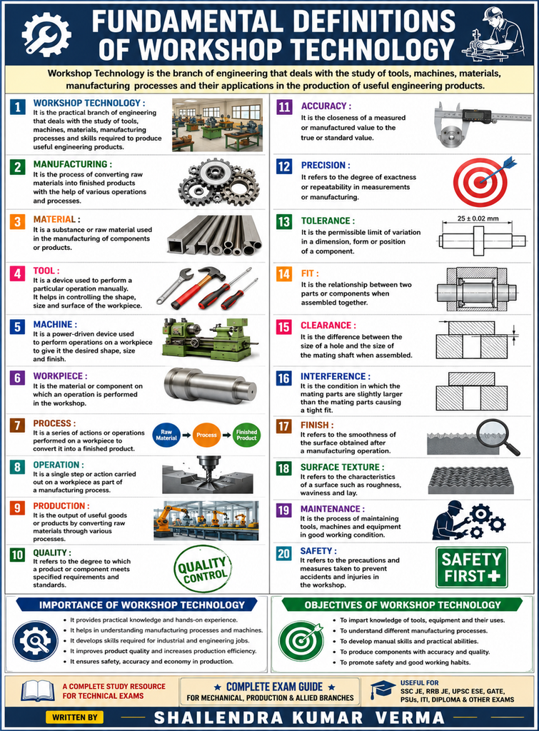
1.1 Introduction
Workshop Technology is a branch of engineering knowledge concerned with the methods, tools, machines, materials and processes used to manufacture, modify, assemble, inspect and maintain engineering components and products.
A student cannot properly understand advanced manufacturing processes without first understanding basic workshop terminology.
For this reason, this book begins with fundamental definitions.
1.2 Workshop
Definition
A workshop is a designated place where manufacturing, machining, fabrication, repair, maintenance, assembly, inspection and other technical activities are carried out using appropriate tools, machines and equipment.
Examples
Fitting workshop
Machine shop
Welding workshop
Foundry
Carpentry shop
Sheet-metal shop
Exam Point
A workshop is not merely a place containing machines. It is an organized working environment where engineering operations are performed.
1.3 Workshop Technology
Definition
Workshop Technology is the systematic study of materials, tools, machines and manufacturing processes used to convert raw materials into useful engineering products.
Main Areas
Workshop Technology includes:
Fitting
Carpentry
Welding
Foundry
Sheet-metal work
Forging
Machining
Grinding
Measurement
Inspection
Heat treatment
1.4 Manufacturing
Definition
Manufacturing is the process of converting raw materials into useful products or components through physical, chemical, mechanical or other controlled processes.
Example
Steel bar → Cutting → Turning → Drilling → Finishing → Finished component
Exam Point
Manufacturing involves more than material removal. It can include:
Casting
Forming
Joining
Machining
Heat treatment
Surface finishing
Additive manufacturing
1.5 Manufacturing Process
Definition
A manufacturing process is a planned sequence of operations by which raw material is converted into a component or product having the required shape, size, properties and surface quality.
Manufacturing processes are commonly classified into major groups such as:
Casting
Forming
Machining
Joining
Heat treatment
Surface treatment
Additive manufacturing
This broad classification is consistent with the way manufacturing-process curricula organize the subject.
1.6 Production
Definition
Production is the overall activity of creating goods or services by utilizing resources such as materials, machines, labour, energy, information and capital.
Difference
Manufacturing mainly concerns the transformation of materials into products.
Production is a broader concept that includes manufacturing along with planning, material handling, inspection, assembly and other activities.
1.7 Production System
Definition
A production system is an organized arrangement of people, machines, materials, methods and other resources used to produce goods efficiently.
Major Types
Job production
Batch production
Mass production
Continuous production
1.8 Process
Definition
A process is a planned method or sequence of actions through which a desired change is produced in a material, component or product.
Example
Turning is a machining process used to remove material from a rotating workpiece.
1.9 Operation
Definition
An operation is a specific manufacturing activity performed to achieve a particular change in a workpiece.
Example
In manufacturing a shaft:
Facing
Turning
Grooving
Threading
Each can be considered a separate operation.
1.10 Job
Definition
A job is a particular workpiece or manufacturing task assigned to a worker, machine or production system.
1.11 Workpiece
Definition
A workpiece is the piece of material on which a manufacturing operation is performed.
Example
During turning, the metal bar mounted on the lathe is the workpiece.
1.12 Raw Material
Definition
Raw material is the basic material used as an input for manufacturing a product.
Examples
Steel bar
Aluminium sheet
Copper rod
Cast iron casting
Metal plate
1.13 Finished Product
Definition
A finished product is a manufactured item that has completed all required production operations and satisfies the specified requirements.
1.14 Semi-Finished Product
Definition
A semi-finished product is a product that has undergone some manufacturing operations but requires additional processing before becoming a final product.
Examples
Rolled steel plate
Forged blank
Rough casting
Extruded section
1.15 Machine
Definition
A machine is a mechanical, electrical or other device that uses energy to perform useful work.
1.16 Machine Tool
Definition
A machine tool is a power-driven machine used to hold and control a workpiece and/or cutting tool to perform manufacturing operations with controlled movement.
Examples
Lathe
Milling machine
Drilling machine
Shaper
Planer
Grinding machine
Important Point
A machine tool is specifically designed for manufacturing operations.
1.17 Cutting Tool
Definition
A cutting tool is a tool used to remove unwanted material from a workpiece in the form of chips during machining.
Examples
Single-point turning tool
Drill
Milling cutter
Reamer

1.18 Hand Tool
Definition
A hand tool is a tool primarily operated manually without direct power-driven cutting action.
Examples
Hammer
File
Hacksaw
Chisel
Screwdriver
Spanner

1.19 Power Tool
Definition
A power tool is a tool operated using an external power source such as electricity, compressed air or hydraulic power.
1.20 Jig
Definition
A jig is a work-holding and tool-guiding device used to locate and hold a workpiece and guide the cutting tool during an operation.
Key Point
Jig = Holds work + Guides tool
1.21 Fixture
Definition
A fixture is a device used to accurately locate and securely hold a workpiece during a manufacturing operation.
Key Point
Fixture = Holds and locates workpiece
Unlike a jig, a conventional fixture does not normally guide the cutting tool.
1.22 Gauge
Definition
A gauge is a measuring or checking device used to determine whether a dimension or characteristic of a component falls within specified limits.
1.23 Inspection
Definition
Inspection is the process of examining a component or product to determine whether it conforms to specified requirements.
1.24 Measurement
Definition
Measurement is the process of determining the numerical value of a physical quantity by comparison with an accepted standard.
1.25 Accuracy
Definition
Accuracy indicates how close a measured value is to the true or accepted value.
Example
If the actual diameter is 50.00 mm and the measured value is 50.01 mm, the measurement has a small error and is relatively accurate.
1.26 Precision
Definition
Precision indicates the degree of agreement among repeated measurements.
Important Difference
Accuracy → Closeness to true value
Precision → Repeatability/consistency
This distinction is extremely important in technical examinations.
1.27 Tolerance
Definition
Tolerance is the permissible variation in a specified dimension.
For a dimension:
50.00 ± 0.02 mm
the total tolerance is:
0.04 mm
1.28 Allowance
Definition
Allowance is the intentional difference between the dimensions of mating parts designed to obtain a desired fit.
Important Difference
Tolerance = Permissible variation
Allowance = Intentional difference between mating dimensions
1.29 Surface Finish
Definition
Surface finish refers to the quality or texture of a manufactured surface resulting from the manufacturing process.
Surface finish is important for:
Friction
Wear
Sealing
Appearance
Fatigue performance
Proper functioning of mating components
1.30 Machining
Definition
Machining is a manufacturing process in which unwanted material is removed from a workpiece to obtain the required shape, size and surface finish.
Examples
Turning
Milling
Drilling
Shaping
Grinding
1.31 Metal Cutting
Definition
Metal cutting is a material-removal process in which a cutting tool removes unwanted material from a metal workpiece, generally in the form of chips.
1.32 Casting
Definition
Casting is a manufacturing process in which molten material is poured into a mould cavity and allowed to solidify to obtain the desired shape.
Basic Steps
Melting → Pouring → Solidification → Removal → Cleaning/Finishing
1.33 Forming
Definition
Metal forming is a manufacturing process in which a metal workpiece is plastically deformed to obtain the desired shape without significant removal of material.
Examples
Forging
Rolling
Extrusion
Drawing
Sheet-metal forming
1.34 Forging
Definition
Forging is a metal-forming process in which a workpiece is plastically deformed by the application of compressive forces using tools, dies, hammers or presses.
1.35 Rolling
Definition
Rolling is a metal-forming process in which metal is passed between rotating rolls to reduce its thickness or change its cross-sectional shape.
1.36 Extrusion
Definition
Extrusion is a metal-forming process in which a billet is forced through a die opening to produce a component or section having a desired cross-sectional profile.
1.37 Drawing
Definition
Drawing is a metal-forming process in which a material is pulled through a die to reduce its cross-sectional area or modify its shape.
1.38 Welding
Definition
Welding is a joining process used to produce a permanent joint between materials by applying suitable heat, pressure, or a combination of heat and pressure, with or without filler material depending on the process.
1.39 Brazing
Definition.
Brazing is a joining process in which a filler metal is melted and distributed between closely fitted surfaces by capillary action, while the base metals are not melted.
1.40 Soldering
Definition
Soldering is a joining process in which a relatively low-melting-point filler metal is used to join components without melting the base materials.
1.41 Fitting
Definition
Fitting is a bench-work operation involving the accurate shaping, sizing, finishing and assembly of components using hand tools and related equipment.
CHAPTER 1 — QUICK REVISION
Term Key Meaning
Workshop Place for technical/manufacturing activities
Manufacturing Conversion of raw material into useful products
Process Planned method of producing a desired change
Operation Specific manufacturing activity
Workpiece Material being processed
Raw Material Basic input material
Machine Tool Power-driven manufacturing machine
Cutting Tool Removes material during machining
Jig Holds work and guides tool
Fixture Holds and locates work
Gauge Checks dimensions/limits
Accuracy Closeness to true value
Precision Repeatability
Tolerance Permissible dimensional variation
Allowance Intentional difference between mating dimensions
Machining Removal of unwanted material
Casting Shaping by pouring molten material into mould
Forging Plastic deformation by compressive forces
Rolling Passing metal between rotating rolls
Extrusion Forcing material through a die
Drawing Pulling material through a die
Welding Permanent joining process
Brazing Joining with filler metal without melting base metal
Soldering Low-temperature filler-metal joining
Fitting Accurate bench-work shaping and assembly
Q51. Which of the following best defines a manufacturing process?
A. A method of transporting raw materials
B. A planned sequence of activities used to convert material into a desired product
C. A method of selling products
D. A method of storing finished goods
Answer: B. A planned sequence of activities used to convert material into a desired product
Explanation: A manufacturing process consists of planned activities that transform raw material into a component or finished product having the required shape, dimensions and properties.
Question
Q52. Which of the following is a primary manufacturing process?
A. Casting
B. Inspection
C. Measurement
D. Transportation
Answer: A. Casting
Explanation: Casting is generally considered a primary manufacturing process because a useful shape is produced directly from molten material.
Question
Q53. Which of the following is primarily a material-removal process?
A. Forging
B. Rolling
C. Machining
D. Casting
Answer: C. Machining
Explanation: Machining removes unwanted material from a workpiece to obtain the required dimensions, geometry and surface finish.
Question
Q54. Which manufacturing process changes the shape mainly by plastic deformation?
A. Metal forming
B. Grinding
C. Drilling
D. Turning
Answer: A. Metal forming
Explanation: Forming processes change the geometry of a material through plastic deformation, generally without significant material removal.
Question
Q55. Which of the following is an example of a metal-forming process?
A. Forging
B. Drilling
C. Grinding
D. Boring
Answer: A. Forging
Explanation: Forging changes the shape of metal through plastic deformation caused mainly by compressive forces.
Question
Q56. Which process involves passing a workpiece between rotating rolls?
A. Extrusion
B. Rolling
C. Drawing
D. Forging
Answer: B. Rolling
Explanation: Rolling uses rotating rolls to reduce thickness or alter the cross-sectional profile of the material.
Question
Q57. Which process forces a billet through a die?
A. Drawing
B. Extrusion
C. Rolling
D. Welding
Answer: B. Extrusion
Explanation: In extrusion, compressive force pushes the billet through a die opening to obtain the desired profile.
Question
Q58. Which process pulls material through a die?
A. Extrusion
B. Drawing
C. Forging
D. Casting
Answer: B. Drawing
Explanation: Drawing reduces the cross-sectional area of a material by pulling it through a die.
Question
Q59. Which of the following is a permanent joining process?
A. Welding
B. Turning
C. Milling
D. Grinding
Answer: A. Welding
Explanation: Welding produces a permanent joint between two or more components.
Question
Q60. In which joining process is a filler metal generally used without melting the base metals?
A. Welding
B. Brazing
C. Forging
D. Rolling
Answer: B. Brazing
Explanation: During brazing, the filler metal melts and flows into the joint while the base materials remain below their melting temperatures.
Question
Q61. Which joining process generally uses a lower-temperature filler metal than brazing?
A. Welding
B. Soldering
C. Forging
D. Casting
Answer: B. Soldering
Explanation: Soldering uses a relatively low-melting-point filler metal and normally does not melt the base materials.
Question
Q62. Which of the following is NOT a material-removal process?
A. Turning
B. Milling
C. Forging
D. Drilling
Answer: C. Forging
Explanation: Forging is a metal-forming process. It changes the shape of the workpiece mainly through plastic deformation rather than removing material.
Question
Q63. Which machine tool is mainly used for producing cylindrical surfaces by turning?
A. Lathe
B. Shaper
C. Planer
D. Slotter
Answer: A. Lathe
Explanation: The lathe is primarily used for turning operations in which the workpiece rotates relative to the cutting tool.
Question
Q64. A machine tool used primarily for producing flat surfaces with a reciprocating cutting tool is:
A. Shaper
B. Lathe
C. Milling machine
D. Grinding machine
Answer: A. Shaper
Explanation: A shaper produces surfaces using the reciprocating motion of a single-point cutting tool.
Question
Q65. Which machine uses a rotating multi-point cutting tool?
A. Milling machine
B. Shaper
C. Planer
D. Lathe
Answer: A. Milling machine
Explanation: A milling cutter rotates and has multiple cutting edges.
Question
Q66. Which of the following is primarily an abrasive machining process?
A. Grinding
B. Forging
C. Casting
D. Welding
Answer: A. Grinding
Explanation: Grinding removes material using abrasive grains contained in a grinding wheel or other abrasive tool.
Question
Q67. Which term describes the amount by which a dimension is allowed to vary?
A. Allowance
B. Tolerance
C. Accuracy
D. Precision
Answer: B. Tolerance
Explanation: Tolerance is the permissible variation in a specified dimension.
Question
Q68. For a dimension of 25.00 ± 0.02 mm, the upper limit is:
A. 24.98 mm
B. 25.00 mm
C. 25.02 mm
D. 25.04 mm
Answer: C. 25.02 mm
Explanation:
Upper limit = 25.00 + 0.02
= 25.02 mm
Question
Q69. For a dimension of 25.00 ± 0.02 mm, the lower limit is:
A. 24.96 mm
B. 24.98 mm
C. 25.02 mm
D. 25.04 mm
Answer: B. 24.98 mm
Explanation:
Lower limit = 25.00 − 0.02
= 24.98 mm
Question
Q70. The total tolerance for 25.00 ± 0.02 mm is:
A. 0.01 mm
B. 0.02 mm
C. 0.04 mm
D. 25.02 mm
Answer: C. 0.04 mm
Explanation:
Total tolerance = Upper limit − Lower limit
= 25.02 − 24.98
= 0.04 mm
Question
Q71. Which term indicates closeness of a measured value to the true value?
A. Precision
B. Accuracy
C. Tolerance
D. Allowance
Answer: B. Accuracy
Explanation: Accuracy indicates how close a measurement is to the true or accepted value.
Question
Q72. Repeated measurements that are very close to one another indicate high:
A. Accuracy only
B. Precision
C. Tolerance
D. Allowance
Answer: B. Precision
Explanation: Precision is associated with repeatability or consistency of measurements.
Question
Q73. A set of measurements may be precise but not accurate when:
A. They are close to one another but far from the true value
B. They are all exactly equal to the true value
C. There is no measurement
D. The instrument has no scale
Answer: A. They are close to one another but far from the true value
Explanation: Precision concerns consistency, whereas accuracy concerns closeness to the true value.
Question
Q74. Which instrument is commonly used for accurate measurement of external dimensions?
A. Hammer
B. Micrometer
C. Chisel
D. Hacksaw
Answer: B. Micrometer
Explanation: A micrometer is a precision measuring instrument used for measuring dimensions such as external diameter or thickness within its range.
Question
Q75. Which instrument can commonly measure external dimensions, internal dimensions and depth?
A. Vernier caliper
B. Hammer
C. File
D. Scriber
Answer: A. Vernier caliper
Explanation: A standard Vernier caliper can measure external and internal dimensions and depth.
Question
Q76. Which tool is primarily used for marking lines on a metal workpiece?
A. Scriber
B. Hammer
C. Spanner
D. File
Answer: A. Scriber
Explanation: A scriber is used to mark fine lines on metal surfaces during layout and marking operations.
Question
Q77. Which tool is commonly used to check whether two surfaces are at right angles?
A. Try square
B. Divider
C. Scriber
D. File
Answer: A. Try square
Explanation: A try square is used to check and mark approximately 90° angles.
Question
Q78. Which tool is used to remove small amounts of material by rubbing its abrasive surface against the workpiece?
A. File
B. Hammer
C. Spanner
D. Scriber
Answer: A. File
Explanation: A file is a hand tool having abrasive teeth used mainly for sizing, shaping and finishing.
Question
Q79. Which tool is commonly used to cut metal manually?
A. Hacksaw
B. Try square
C. Divider
D. Micrometer
Answer: A. Hacksaw
Explanation: A hacksaw is a hand-operated cutting tool used for cutting metal and other materials.
Question
Q80. Which of the following is a marking tool?
A. Divider
B. Lathe
C. Grinding wheel
D. Drill press
Answer: A. Divider
Explanation: A divider is commonly used for transferring measurements and marking arcs or circles on a workpiece.
Question
Q81. Which operation involves producing an external cylindrical surface on a lathe?
A. Turning
B. Milling
C. Grinding
D. Broaching
Answer: A. Turning
Explanation: Turning removes material from the external surface of a rotating workpiece using a single-point cutting tool.
Question
Q82. Which lathe operation produces a flat surface at the end of a cylindrical workpiece?
A. Facing
B. Knurling
C. Threading
D. Grooving
Answer: A. Facing
Explanation: Facing produces a flat surface perpendicular to the axis of rotation.
Question
Q83. Which operation is used to produce a helical thread on a workpiece?
A. Thread cutting
B. Facing
C. Filing
D. Grinding only
Answer: A. Thread cutting
Explanation: Thread cutting on a lathe produces helical threads by coordinating spindle rotation with longitudinal tool movement.
Question
Q84. Which operation produces a roughened pattern on a cylindrical surface?
A. Knurling
B. Facing
C. Boring
D. Reaming
Answer: A. Knurling
Explanation: Knurling produces a patterned surface, commonly to improve grip.
Question
Q85. Which operation is used to enlarge an existing hole accurately?
A. Boring
B. Forging
C. Rolling
D. Casting
Answer: A. Boring
Explanation: Boring enlarges and improves an existing hole using a single-point or suitable boring tool.
Question
Q86. Which operation is generally used to improve the dimensional accuracy and finish of an existing hole?
A. Reaming
B. Forging
C. Rolling
D. Welding
Answer: A. Reaming
Explanation: Reaming is a finishing operation used to bring an existing hole closer to the required size and improve its surface finish.
Question
Q87. Which process is used to produce a hole initially in a solid workpiece?
A. Drilling
B. Boring
C. Reaming
D. Honing
Answer: A. Drilling
Explanation: Drilling is normally used to produce a new circular hole in a solid workpiece.
Question
Q88. Which of the following is a surface-finishing process?
A. Grinding
B. Forging
C. Casting
D. Extrusion
Answer: A. Grinding
Explanation: Grinding can produce accurate dimensions and improved surface finish.
Question
Q89. Which process uses a mould cavity?
A. Casting
B. Turning
C. Milling
D. Drilling
Answer: A. Casting
Explanation: Casting uses a mould cavity into which molten material is introduced.
Question
Q90. The cavity in a mould generally represents the:
A. Cutting-tool geometry
B. Desired external shape of the casting
C. Machine-bed shape
D. Measuring-instrument shape
Answer: B. Desired external shape of the casting
Explanation: The mould cavity provides the required geometry into which molten material solidifies.
Question
Q91. Which component of a casting system helps compensate for shrinkage during solidification?
A. Riser
B. Cutting tool
C. Fixture
D. Micrometer
Answer: A. Riser
Explanation: A riser acts as a reservoir of molten metal and helps feed the casting during solidification to compensate for shrinkage.
Question
Q92. A pattern is primarily used in:
A. Casting
B. Turning
C. Grinding
D. Welding
Answer: A. Casting
Explanation: A pattern is used to produce the mould cavity required for casting.
Question
Q93. Which of the following is associated with moulding?
A. Foundry
B. Machine shop only
C. Fitting bench only
D. Metrology laboratory only
Answer: A. Foundry
Explanation: Moulding is a major activity in foundry work, where mould cavities are prepared for casting.
Question
Q94. Which of the following is primarily a joining operation?
A. Welding
B. Turning
C. Drilling
D. Milling
Answer: A. Welding
Explanation: Welding is used to create a permanent joint between components.
Question
Q95. Which process can join metals using a filler metal while keeping the base metals below their melting temperature?
A. Brazing
B. Turning
C. Milling
D. Drilling
Answer: A. Brazing
Explanation: Brazing relies on melting and flowing of the filler metal while the base metals remain solid.
Question
Q96. Which term describes the ability of a material to return to its original shape after removal of load, within its elastic limit?
A. Elasticity
B. Plasticity
C. Brittleness
D. Hardness
Answer: A. Elasticity
Explanation: Elasticity is the property by which a material tends to regain its original shape after the deforming load is removed, provided the elastic limit has not been exceeded.
Question
Q97. A material that fractures with little plastic deformation is described as:
A. Ductile
B. Brittle
C. Malleable
D. Elastic
Answer: B. Brittle
Explanation: Brittle materials generally undergo little plastic deformation before fracture.
Question
Q98. The ability of a material to withstand deformation under load is related to:
A. Strength
B. Colour
C. Density only
D. Thermal conductivity only
Answer: A. Strength
Explanation: Strength is the ability of a material to withstand applied loads without failure.
Question
Q99. Which term represents resistance to deformation under elastic loading?
A. Stiffness
B. Ductility
C. Plasticity
D. Brittleness
Answer: A. Stiffness
Explanation: Stiffness is the resistance offered by a material or component to elastic deformation.
Question
Q100. Which sequence represents a typical basic manufacturing transformation?
A. Finished product → raw material → manufacturing
B. Raw material → manufacturing processes → finished product
C. Product → advertising → raw material
D. Inspection → raw material → transportation
Answer: B. Raw material → manufacturing processes → finished product
Explanation: Manufacturing begins with raw or semi-finished material and applies suitable processes to obtain a product meeting the required specifications.
Question
Important Process Differences
Process Basic Principle
Casting Molten material → mould → solidification
Forging Plastic deformation by compressive force
Rolling Material passes between rotating rolls
Extrusion Material forced through die
Drawing Material pulled through die
Machining Unwanted material removed
Welding Permanent joining
Brazing Filler metal joins parts without melting base metals
Soldering Lower-temperature filler-metal joining
Grinding Abrasive material removal
CHAPTER 2 — ENGINEERING MATERIALS
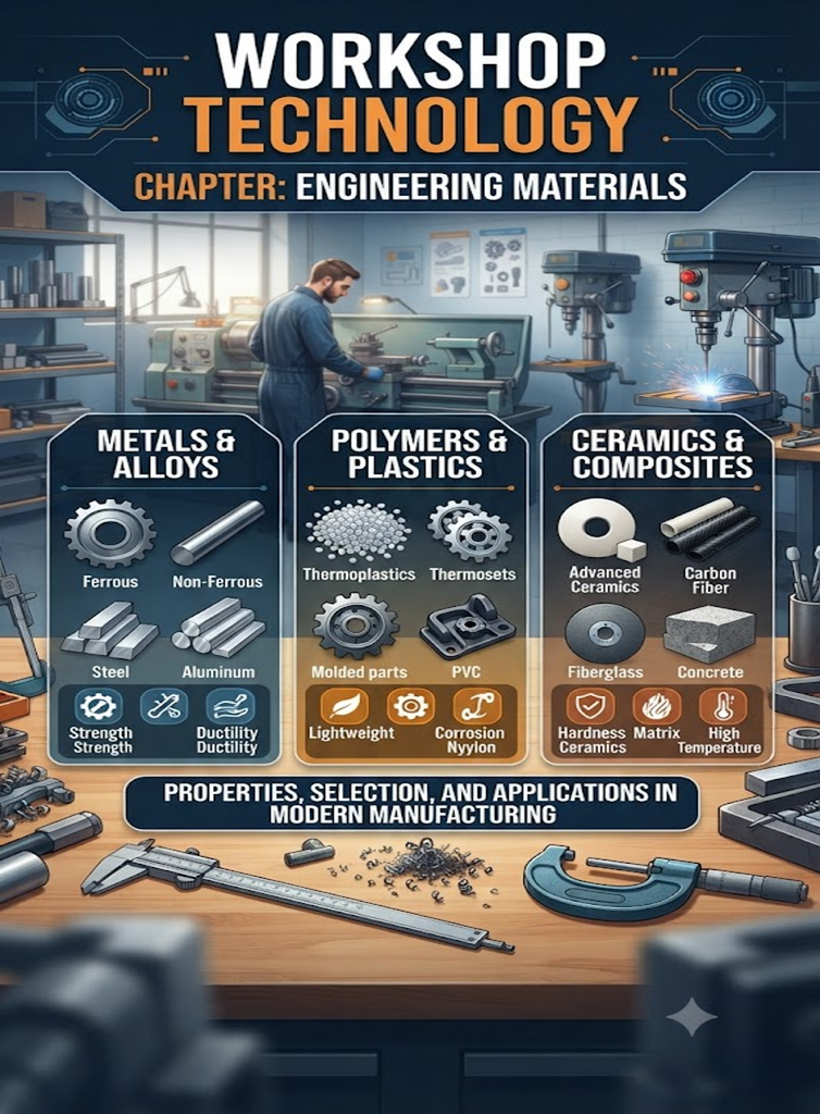
2.1 Introduction
Engineering materials are the basic materials used for manufacturing machines, tools, structures, components and other engineering products.
A proper understanding of engineering materials is essential in Workshop Technology, because the selection of a material depends on its strength, hardness, toughness, ductility, machinability, corrosion resistance, cost, availability and intended application.
Engineering materials can broadly be classified into:
Metallic materials
Non-metallic materials
Composite materials
Metallic materials are further divided into:
Ferrous materials
Non-ferrous materials
2.2 Engineering Material
Definition
An engineering material is a material having suitable physical, mechanical, chemical or thermal properties that can be used for manufacturing engineering components, machines, tools or structures.
Examples
Steel
Cast iron
Aluminium
Copper
Brass
Bronze
Plastics
Ceramics
Composites
Exam Point
Material selection depends on the required properties and application of the component.
2.3 Metals
Definition
A metal is an element or material generally characterized by good electrical and thermal conductivity, metallic lustre, ductility and malleability.
Common Engineering Metals
Iron
Copper
Aluminium
Zinc
Nickel
Magnesium
Titanium
2.4 Ferrous Materials
Definition
Ferrous materials are materials in which iron is the principal constituent.
Major Examples
Cast iron
Steel
Carbon steel
Alloy steel
Stainless steel
Important Point
The word ferrous is derived from ferrum, the Latin word for iron.
2.5 Non-Ferrous Materials
Definition
Non-ferrous materials are metals and alloys in which iron is not the principal constituent.
Examples
Aluminium
Copper
Zinc
Magnesium
Titanium
Brass
Bronze
Major Characteristics
Many non-ferrous metals offer:
Good corrosion resistance
Low density
Good electrical conductivity
Good thermal conductivity
2.6 Alloy
Definition
An alloy is a metallic material formed by combining two or more elements, at least one of which is generally a metal, to obtain desirable properties.
Examples
Brass = Copper + Zinc
Bronze = Copper + Tin
(as the conventional/basic definition)
Steel = Iron + Carbon, with other elements possibly present.
Why Are Alloys Used?
Alloying can improve:
Strength
Hardness
Wear resistance
Corrosion resistance
Machinability
Heat resistance
2.7 Steel
Definition
Steel is an iron-based alloy containing carbon as an important alloying element, generally with carbon content below that of cast irons and with possible additions of other alloying elements.
Common Types
Plain carbon steel
Low-carbon steel
Medium-carbon steel
High-carbon steel
Alloy steel
Stainless steel
2.8 Carbon Steel
Definition
Carbon steel is steel in which carbon is the principal alloying element and the properties are primarily controlled by carbon content, with other elements present in relatively limited amounts.
Classification
Depending on carbon content, carbon steels are commonly classified as:
Low-carbon steel
Medium-carbon steel
High-carbon steel
2.9 Low-Carbon Steel
Definition
Low-carbon steel is steel containing a relatively low percentage of carbon.
General Characteristics
Good ductility
Good weldability
Good machinability
Relatively low hardness
Relatively low strength compared with higher-carbon steels
Applications
Sheets
Structural components
Automobile components
Nuts and bolts
General fabrication
2.10 Medium-Carbon Steel
Definition
Medium-carbon steel contains more carbon than low-carbon steel and generally provides a balance between strength, hardness and ductility.
Applications
Shafts
Axles
Gears
Machine components
2.11 High-Carbon Steel
Definition
High-carbon steel contains a relatively high percentage of carbon and generally has higher hardness and strength but lower ductility than low-carbon steel.
Applications
Cutting tools
Springs
High-strength wires
Dies
Wear-resistant components
2.12 Cast Iron
Definition
Cast iron is an iron-carbon alloy containing a relatively high carbon content, generally above the carbon content range of steels.
General Characteristics
Good castability
Good compressive strength
Good wear resistance in many grades
Good vibration-damping capacity
Generally brittle compared with steels
Applications
Machine beds
Engine blocks
Pump bodies
Pipes
Housings
2.13 Grey Cast Iron
Definition
Grey cast iron is cast iron in which carbon is present predominantly in the form of graphite flakes, giving the fractured surface a grey appearance.
Characteristics
Good machinability
Good damping capacity
Good castability
Relatively brittle
Applications
Machine beds
Engine blocks
Housings
Bases
2.14 White Cast Iron
Definition
White cast iron is cast iron in which carbon is predominantly present in combined form, mainly as cementite, giving a white appearance on fracture.
Characteristics
High hardness
High wear resistance
Poor machinability
Brittle
2.15 Malleable Cast Iron
Definition
Malleable cast iron is produced by heat treating suitable white cast iron to improve its ductility and toughness.
Applications
Pipe fittings
Brackets
Small machine components
2.16 Ductile Cast Iron
Definition
Ductile cast iron, also called nodular cast iron, is cast iron in which graphite occurs mainly in spheroidal or nodular form.
Characteristics
Better ductility than grey cast iron
Good strength
Good toughness
Good wear resistance
2.17 Alloy Steel
Definition
Alloy steel is steel containing deliberate additions of alloying elements such as chromium, nickel, molybdenum, manganese or vanadium to obtain specific properties.
Applications
Automobile components
Gears
Shafts
Pressure vessels
Aerospace components
Dies and tools
2.18 Stainless Steel
Definition
Stainless steel is a group of alloy steels containing sufficient chromium to provide substantial resistance to corrosion through formation of a protective chromium-rich oxide film.
Applications
Kitchen equipment
Chemical-processing equipment
Medical instruments
Food-processing equipment
Architectural applications
Exam Point
Chromium is the key alloying element associated with stainless-steel corrosion resistance.
2.19 Copper
Definition
Copper is a non-ferrous metal known for its excellent electrical and thermal conductivity, ductility and corrosion resistance.
Applications
Electrical wires
Electrical components
Heat exchangers
Pipes
Conductors
2.20 Aluminium
Definition
Aluminium is a lightweight non-ferrous metal having good corrosion resistance, good thermal and electrical conductivity and good formability.
Applications
Aircraft components
Automobile components
Electrical applications
Window frames
Packaging
Heat exchangers
2.21 Brass
Definition
Brass is a copper-zinc alloy.
Characteristics
Good machinability
Good corrosion resistance
Attractive appearance
Good electrical and thermal conductivity compared with many other engineering materials
Applications
Valves
Fittings
Fasteners
Electrical components
Decorative components
Exam Point
Brass → Copper + Zinc
2.22 Bronze
Definition
Bronze is traditionally a copper-tin alloy, although the term is also used for several copper-based alloys containing other elements.
Applications
Bearings
Bushes
Gears
Marine components
Valves
Exam Point
Traditional bronze → Copper + Tin
2.23 Zinc
Definition
Zinc is a non-ferrous metal commonly used for corrosion protection of steel and in the production of alloys such as brass.
Major Application
Galvanizing uses zinc coating to protect steel or iron from corrosion.
2.24 Magnesium
Definition
Magnesium is a very lightweight structural metal used where low weight is important.
Applications
Aerospace components
Automobile components
Portable equipment
Lightweight structural parts
2.25 Titanium
Definition
Titanium is a strong, relatively lightweight metal with excellent corrosion resistance and a high strength-to-weight ratio.
Applications
Aerospace
Chemical processing
Medical implants
Marine applications
2.26 Mechanical Properties
Definition
Mechanical properties describe how a material behaves when subjected to mechanical forces or loads.
Important mechanical properties include:
Strength
Hardness
Toughness
Ductility
Malleability
Elasticity
Plasticity
Stiffness
Resilience
Fatigue strength
Creep resistance
2.27 Strength
Definition
Strength is the ability of a material to withstand an applied load without failure.
Important types include:
Tensile strength
Compressive strength
Shear strength
Bending strength
2.28 Hardness
Definition
Hardness is the resistance of a material to localized plastic deformation such as indentation, scratching or wear.
Common Hardness Tests
Brinell
Rockwell
Vickers
2.29 Toughness
Definition
Toughness is the ability of a material to absorb energy and undergo deformation before fracture.
Important Point
A tough material can generally withstand impact or sudden loading better than a brittle material.
2.30 Ductility
Definition
Ductility is the ability of a material to undergo significant plastic deformation under tensile loading before fracture.
Example
Copper is generally considered a highly ductile engineering metal.
2.31 Malleability
Definition
Malleability is the ability of a material to undergo plastic deformation under compressive loading and be formed into thin sheets without cracking.
Exam Point
Ductility → tensile deformation
Malleability → compressive deformation
2.32 Brittleness
Definition
Brittleness is the tendency of a material to fracture with little or limited plastic deformation.
Example
Many forms of cast iron are relatively brittle compared with ductile steels.
2.33 Elasticity
Definition
Elasticity is the property by which a material tends to return to its original shape and dimensions after removal of the applied load, provided the elastic limit has not been exceeded.
2.34 Plasticity
Definition
Plasticity is the ability of a material to undergo permanent deformation without fracture.
2.35 Stiffness
Definition
Stiffness is the resistance offered by a material or component to elastic deformation.
Exam Point
A material may have high strength but a component’s deformation under load is also strongly related to its stiffness.
2.36 Resilience
Definition
Resilience is the ability of a material to absorb energy within its elastic limit and release that energy when the load is removed.
2.37 Fatigue
Definition
Fatigue is the progressive failure of a material caused by repeated or fluctuating stresses, often at stress levels below the material’s static strength.
Common Examples
Rotating shafts
Springs
Aircraft components
Connecting rods
2.38 Creep
Definition
Creep is the slow, time-dependent deformation of a material under sustained load, particularly at elevated temperature.
Important Point
Creep is especially important in:
Boilers
Turbines
Engines
High-temperature piping
Power-plant components
2.39 Wear
Definition
Wear is the progressive loss or displacement of material from a surface due to interaction with another surface or environment.
Common Types
Adhesive wear
Abrasive wear
Corrosive wear
Fatigue wear
2.40 Corrosion Resistance
Definition
Corrosion resistance is the ability of a material to resist deterioration caused by chemical or electrochemical interaction with its environment.
Example
Stainless steel generally has much better corrosion resistance than ordinary carbon steel because of its chromium-containing passive surface film.
QUICK REVISION TABLE
Material/Property Key Point
Ferrous material Iron is principal constituent
Non-ferrous material Iron is not principal constituent
Steel Iron-based alloy with carbon as an important constituent
Cast iron High-carbon iron alloy
Brass Copper + Zinc
Bronze Traditionally Copper + Tin
Stainless steel Chromium-containing corrosion-resistant steel
Copper Excellent electrical conductivity
Aluminium Lightweight and corrosion resistant
Strength Resistance to applied load
Hardness Resistance to indentation/wear
Toughness Energy absorption before fracture
Ductility Plastic deformation in tension
Malleability Plastic deformation in compression
Elasticity Recovery after removal of load
Plasticity Permanent deformation
Stiffness Resistance to elastic deformation
Resilience Elastic energy absorption
Fatigue Failure under repeated/fluctuating stress
Creep Time-dependent deformation under sustained load
Wear Progressive material loss
Corrosion resistance Resistance to environmental deterioration
CHAPTER 2 — IMPORTANT EXAM POINTS
Remember These Combinations
Brass → Cu + Zn
Bronze → Cu + Sn
Stainless Steel → Cr is essential for corrosion resistance
Ferrous → Iron-based
Ductility → Tensile deformation
Malleability → Compressive deformation
Hardness → Indentation
Toughness → Energy absorption before fracture
Elasticity → Returns after load removal
Plasticity → Permanent deformation
Fatigue → Repeated/fluctuating load
Creep → Time + sustained load
Q1. Which of the following is a ferrous material?
A. Aluminium
B. Copper
C. Cast iron
D. Brass
Answer: C. Cast iron
Explanation: Ferrous materials are iron-based materials. Cast iron contains iron as its principal constituent.
Question
Q2. Which of the following is a non-ferrous metal?
A. Mild steel
B. Cast iron
C. Aluminium
D. Carbon steel
Answer: C. Aluminium
Explanation: Aluminium is a non-ferrous metal because iron is not its principal constituent.
Question
Q3. Brass is primarily an alloy of:
A. Copper and tin
B. Copper and zinc
C. Iron and carbon
D. Aluminium and copper
Answer: B. Copper and zinc
Explanation: Brass is conventionally defined as a copper-zinc alloy.
Question
Q4. Bronze is tr
aditionally an alloy of:
A. Copper and zinc
B. Copper and tin
C. Iron and carbon
D. Aluminium and magnesium
Answer: B. Copper and tin
Explanation: Traditional bronze is a copper-tin alloy. There are also many other copper-based alloys commercially called bronzes.
Question
Q5. The principal alloying element responsible for the corrosion resistance of stainless steel is:
A. Carbon
B. Chromium
C. Sulphur
D. Silicon
Answer: B. Chromium
Explanation: Chromium promotes formation of a thin, protective passive oxide film that provides stainless steels with their characteristic corrosion resistance.
Question
Q6. Which material is generally known for excellent electrical conductivity?
A. Copper
B. Cast iron
C. High-carbon steel
D. Glass
Answer: A. Copper
Explanation: Copper has very high electrical conductivity and is widely used for electrical conductors and cables.
Question
Q7. Which of the following is a major advantage of aluminium?
A. Very high density
B. Low density
C. Extremely high hardness in pure form
D. Poor corrosion resistance
Answer: B. Low density
Explanation: Aluminium is lightweight and has good corrosion resistance, making it useful in transport and aerospace applications.
Question
Q8. Which material is commonly used for electrical wires?
A. Copper
B. Cast iron
C. Tool steel
D. White cast iron
Answer: A. Copper
Explanation: Copper combines excellent electrical conductivity with good ductility and is therefore widely used for electrical wiring.
Question
Q9. Which of the following is a ferrous alloy?
A. Brass
B. Bronze
C. Steel
D. Aluminium alloy
Answer: C. Steel
Explanation: Steel is an iron-based alloy and is therefore classified as a ferrous material.
Question
Q10. Which of the following is generally considered a lightweight engineering metal?
A. Aluminium
B. Lead
C. Cast iron
D. Steel
Answer: A. Aluminium
Explanation: Aluminium has relatively low density compared with steel and many other structural metals.
Question
Q11. Which property represents resistance to indentation?
A. Ductility
B. Hardness
C. Elasticity
D. Plasticity
Answer: B. Hardness
Explanation: Hardness is commonly evaluated through resistance to indentation, scratching or localized plastic deformation.
Question
Q12. Which property represents the ability to absorb energy before fracture?
A. Toughness
B. Hardness
C. Stiffness
D. Brittleness
Answer: A. Toughness
Explanation: Toughness is the ability to absorb energy and undergo deformation before fracture.
Question
Q13. The ability of a material to undergo plastic deformation in tension before fracture is called:
A. Ductility
B. Malleability
C. Hardness
D. Stiffness
Answer: A. Ductility
Explanation: Ductility is particularly associated with plastic deformation under tensile loading.
Question
Q14. The ability of a material to be formed into thin sheets by compressive deformation is called:
A. Ductility
B. Malleability
C. Toughness
D. Hardness
Answer: B. Malleability
Explanation: Malleability is the ability to undergo plastic deformation under compression without cracking.
Question
Q15. Which property allows a material to regain its original shape after removal of load?
A. Plasticity
B. Elasticity
C. Brittleness
D. Toughness
Answer: B. Elasticity
Explanation: Within its elastic limit, an elastic material returns approximately to its original dimensions after removal of the load.
Question
Q16. Which property represents resistance to elastic deformation?
A. Stiffness
B. Ductility
C. Malleability
D. Plasticity
Answer: A. Stiffness
Explanation: Stiffness indicates resistance to elastic deformation.
Question
Q17. A brittle material generally undergoes:
A. Large plastic deformation before fracture
B. Little plastic deformation before fracture
C. Unlimited elastic deformation
D. No deformation at all
Answer: B. Little plastic deformation before fracture
Explanation: Brittle materials generally fracture with relatively little plastic deformation.
Question
Q18. Which of the following is generally more ductile?
A. Glass
B. Copper
C. White cast iron
D. Ceramics
Answer: B. Copper
Explanation: Copper is a highly ductile metal and can undergo considerable plastic deformation before fracture.
Question
Q19. Which property is particularly important for materials subjected to impact loading?
A. Toughness
B. Density
C. Thermal expansion
D. Electrical resistance
Answer: A. Toughness
Explanation: Toughness is the ability to absorb energy before fracture, making it particularly important under impact or shock loading.
Question
Q20. Fatigue failure is generally associated with:
A. Repeated or fluctuating stresses
B. Constant temperature only
C. Static pressure only
D. Melting
Answer: A. Repeated or fluctuating stresses
Explanation: Fatigue is progressive failure caused by repeated or fluctuating stresses.
Question
Q21. Creep is:
A. Sudden fracture due to impact
B. Time-dependent deformation under sustained load
C. Surface scratching
D. Plastic deformation during forging only
Answer: B. Time-dependent deformation under sustained load
Explanation: Creep is a slow, time-dependent deformation that becomes particularly important at elevated temperatures.
Question
Q22. Creep is particularly important in:
A. High-temperature components
B. Room-temperature wooden furniture only
C. Measuring instruments only
D. Hand tools only
Answer: A. High-temperature components
Explanation: Creep becomes significant in components subjected to sustained stress at elevated temperatures, such as turbine and boiler components.
Question
Q23. Which of the following is a common hardness test?
A. Brinell test
B. Tensile test
C. Compression test
D. Impact-only test
Answer: A. Brinell test
Explanation: Brinell, Rockwell and Vickers are widely used hardness-testing methods.
Question
Q24. Which hardness test commonly uses a diamond pyramid indenter?
A. Vickers
B. Brinell
C. Charpy
D. Izod
Answer: A. Vickers
Explanation: The Vickers hardness test uses a diamond pyramid-shaped indenter.
Question
Q25. The Brinell hardness test commonly uses:
A. A steel or carbide ball indenter
B. A diamond cone only
C. A flat plate only
D. A cutting tool
Answer: A. A steel or carbide ball indenter
Explanation: Brinell testing uses a spherical indenter, traditionally hardened steel and commonly tungsten carbide in modern practice.
Question
Q26. Which of the following is an example of a mechanical property?
A. Hardness
B. Colour
C. Density only
D. Electrical conductivity
Answer: A. Hardness
Explanation: Hardness describes material response to mechanical loading and localized deformation.
Question
Q27. Which of the following is a physical property?
A. Density
B. Toughness
C. Hardness
D. Ductility
Answer: A. Density
Explanation: Density is a physical property, whereas hardness, toughness and ductility are mechanical properties.
Question
Q28. Which material is commonly used for machine beds because of its good vibration-damping capacity?
A. Grey cast iron
B. Aluminium foil
C. Copper wire
D. Glass
Answer: A. Grey cast iron
Explanation: Grey cast iron has good vibration-damping characteristics and is therefore widely used for machine-tool beds and bases.
Question
Q29. The graphite in ordinary grey cast iron is predominantly present as:
A. Spherical particles
B. Flakes
C. Needles only
D. Fibres
Answer: B. Flakes
Explanation: Grey cast iron characteristically contains graphite flakes in its microstructure.
Question
Q30. In ductile cast iron, graphite is predominantly present in:
A. Flake form
B. Nodular/spheroidal form
C. Continuous sheet form
D. Powder form
Answer: B. Nodular/spheroidal form
Explanation: The graphite in ductile or nodular cast iron is mainly spheroidal, improving ductility and toughness compared with grey cast iron.
Question
Q31. Which type of cast iron generally has high hardness and poor machinability?
A. White cast iron
B. Grey cast iron
C. Ductile cast iron
D. Malleable cast iron
Answer: A. White cast iron
Explanation: White cast iron contains carbon predominantly in combined form, especially cementite, making it hard and wear-resistant but difficult to machine.
Question
Q32. Malleable cast iron is produced by heat treatment of:
A. Grey cast iron
B. White cast iron
C. Pure aluminium
D. Brass
Answer: B. White cast iron
Explanation: Suitable white cast iron is heat treated to produce malleable cast iron with improved ductility and toughness.
Question
Q33. Which cast iron generally has the best combination of strength and ductility among common cast irons?
A. Ductile cast iron
B. White cast iron
C. Grey cast iron
D. Chilled cast iron
Answer: A. Ductile cast iron
Explanation: The nodular graphite structure of ductile cast iron gives it substantially better ductility and toughness than grey or white cast iron.
Question
Q34. Which material is commonly used for machine-tool beds?
A. Grey cast iron
B. Pure zinc
C. Brass sheet
D. Lead
Answer: A. Grey cast iron
Explanation: Grey cast iron combines good castability, machinability and vibration damping, making it suitable for machine beds.
Question
Q35. Which of the following is a low-carbon steel application?
A. General fabrication and structural components
B. High-speed cutting tools only
C. Grinding-wheel abrasives
D. Glass manufacturing
Answer: A. General fabrication and structural components
Explanation: Low-carbon steels are ductile, weldable and suitable for many general fabrication and structural applications.
Question
Q36. As carbon content in plain carbon steel generally increases, which property tends to increase?
A. Hardness
B. Ductility
C. Weldability
D. Formability
Answer: A. Hardness
Explanation: Increasing carbon content generally increases hardness and strength after suitable processing, while ductility and weldability tend to decrease.
Question
Q37. Which type of steel generally has the highest carbon content among the following?
A. Low-carbon steel
B. Medium-carbon steel
C. High-carbon steel
D. Mild steel
Answer: C. High-carbon steel
Explanation: High-carbon steel contains more carbon than low- and medium-carbon steels.
Question
Q38. Which material is commonly used for springs because of its ability to withstand elastic deformation?
A. Spring steel
B. Grey cast iron
C. Pure lead
D. Glass
Answer: A. Spring steel
Explanation: Spring steels are designed to provide suitable strength and elastic properties for repeated spring action.
Question
Q39. Which alloying element is strongly associated with improved wear and corrosion resistance in many alloy steels?
A. Chromium
B. Oxygen
C. Hydrogen
D. Sulphur only
Answer: A. Chromium
Explanation: Chromium can improve hardness, wear resistance and corrosion resistance depending on composition and heat treatment.
Question
Q40. Nickel in steel can contribute to:
A. Toughness and corrosion resistance
B. Complete loss of strength
C. Zero ductility in every case
D. Elimination of all heat treatment
Answer: A. Toughness and corrosion resistance
Explanation: Nickel is used in alloy steels to improve properties such as toughness and corrosion resistance.
Question
Q41. Which of the following is a non-ferrous alloy?
A. Brass
B. Carbon steel
C. Cast iron
D. Stainless steel
Answer: A. Brass
Explanation: Brass is a copper-zinc alloy and does not have iron as its principal constituent.
Question
Q42. Which material is commonly used for bearings and bushes?
A. Bronze
B. Glass
C. Pure iron only
D. Concrete
Answer: A. Bronze
Explanation: Several bronze alloys have good wear resistance and suitable friction characteristics and are used for bearings and bushes.
Question
Q43. Which metal is commonly used as a coating for protecting steel against atmospheric corrosion?
A. Zinc
B. Copper
C. Tin only
D. Lead only
Answer: A. Zinc
Explanation: Zinc coating, known as galvanizing, is widely used to protect iron and steel from corrosion.
Question
Q44. Galvanizing generally involves coating steel with:
A. Zinc
B. Copper
C. Aluminium only
D. Carbon
Answer: A. Zinc
Explanation: Galvanizing is the application of a zinc coating to iron or steel for corrosion protection.
Question
Q45. Which metal has a high strength-to-weight ratio and excellent corrosion resistance?
A. Titanium
B. Lead
C. Grey cast iron
D. Pure zinc
Answer: A. Titanium
Explanation: Titanium and its alloys are valued for high specific strength and excellent corrosion resistance.
Question
Q46. Which material is widely used in aerospace applications because of its low density?
A. Aluminium alloys
B. Grey cast iron
C. Lead
D. White cast iron
Answer: A. Aluminium alloys
Explanation: Aluminium alloys provide relatively low density with useful strength and corrosion resistance.
Question
Q47. Which of the following is generally a good conductor of both heat and electricity?
A. Copper
B. Rubber
C. Glass
D. Wood
Answer: A. Copper
Explanation: Copper has excellent electrical and thermal conductivity.
Question
Q48. Which material is generally characterized by good castability and vibration damping?
A. Grey cast iron
B. Pure aluminium
C. Copper
D. Titanium
Answer: A. Grey cast iron
Explanation: Grey cast iron flows well during casting and its graphite structure provides useful vibration damping.
Question
Q49. Which property is most directly associated with resistance to scratching?
A. Hardness
B. Ductility
C. Malleability
D. Plasticity
Answer: A. Hardness
Explanation: Hardness is commonly associated with resistance to scratching, indentation and wear.
Question
Q50. Which property is most important when a material must withstand repeated loading for a long period?
A. Fatigue strength
B. Colour
C. Density alone
D. Melting point alone
Answer: A. Fatigue strength
Explanation: Components subjected to repeated or fluctuating loads require adequate fatigue strength to resist fatigue failure.
Question
Q51. Which of the following is NOT a ferrous material?
A. Steel
B. Cast iron
C. Stainless steel
D. Brass
Answer: D. Brass
Explanation: Brass is a copper-zinc alloy and is classified as a non-ferrous material.
Question
Q52. Which of the following is a copper-based alloy?
A. Brass
B. Mild steel
C. Cast iron
D. Stainless steel
Answer: A. Brass
Explanation: Brass is primarily composed of copper and zinc.
Question
Q53. Which material is particularly suitable for electrical conductors?
A. Copper
B. White cast iron
C. High-carbon steel
D. Grey cast iron
Answer: A. Copper
Explanation: Copper’s high electrical conductivity and ductility make it suitable for electrical conductors.
Question
Q54. Which property is particularly desirable in a material used for a cutting tool?
A. High hardness
B. Very low hardness
C. Very high ductility only
D. Very low wear resistance
Answer: A. High hardness
Explanation: Cutting tools must resist deformation and wear at the cutting edge, so high hardness is essential.
Question
Q55. Which material property is most closely associated with resistance to wear?
A. Hardness
B. Malleability
C. Elasticity
D. Thermal expansion
Answer: A. Hardness
Explanation: Hardness generally contributes significantly to resistance against abrasive and surface wear, although wear behavior depends on several factors.
Q56. Which material is generally easier to plastically deform?
A. Ductile material
B. Brittle material
C. Glass
D. White cast iron
Answer: A. Ductile material
Explanation: Ductile materials can undergo significant plastic deformation before fracture.
Question
Q57. Which property is important for a material used in sheet-metal forming?
A. Malleability
B. Brittleness
C. Extremely low ductility
D. Poor formability
Answer: A. Malleability
Explanation: Malleability enables materials to undergo compressive plastic deformation and be formed into sheets.
Question
Q58. Which of the following materials is generally brittle?
A. Grey cast iron
B. Copper
C. Aluminium
D. Mild steel
Answer: A. Grey cast iron
Explanation: Grey cast iron is relatively brittle because of its flake-graphite structure.
Question
Q59. Which property is associated with resistance to sudden impact?
A. Toughness
B. Density
C. Conductivity
D. Thermal expansion
Answer: A. Toughness
Explanation: Toughness measures a material’s ability to absorb energy before fracture and is important under impact loading.
Question
Q60. Which property is particularly important in a material subjected to high temperature for a long time?
A. Creep resistance
B. Colour
C. Electrical resistance only
D. Surface appearance only
Answer: A. Creep resistance
Explanation: Components under sustained stress at high temperatures can undergo creep, so creep resistance is important.
Question
Q61. Which of the following is a common alloying element in stainless steel?
A. Chromium
B. Sodium
C. Calcium
D. Potassium
Answer: A. Chromium
Explanation: Chromium is essential to the corrosion resistance of stainless steels.
Question
Q62. Which of the following is a lightweight non-ferrous metal?
A. Aluminium
B. Cast iron
C. Steel
D. High-carbon steel
Answer: A. Aluminium
Explanation: Aluminium has relatively low density and is widely used where weight reduction is important.
Question
Q63. Which material is commonly used for engine blocks?
A. Cast iron
B. Glass
C. Copper wire
D. Rubber
Answer: A. Cast iron
Explanation: Cast irons, particularly grey cast iron, have good castability, machinability and vibration-damping characteristics. Aluminium alloys are also widely used for engine blocks.
Question
Q64. Which type of cast iron has graphite in nodular form?
A. Ductile cast iron
B. Grey cast iron
C. White cast iron
D. Chilled cast iron
Answer: A. Ductile cast iron
Explanation: Ductile cast iron is characterized by spheroidal or nodular graphite.
Question
Q65. Which cast iron has graphite predominantly in flake form?
A. Grey cast iron
B. Ductile cast iron
C. Malleable cast iron
D. White cast iron
Answer: A. Grey cast iron
Explanation: Graphite flakes give grey cast iron its characteristic appearance and contribute to good vibration damping.
Question
Q66. Which cast iron contains carbon mainly in combined form?
A. White cast iron
B. Grey cast iron
C. Ductile cast iron
D. Malleable cast iron
Answer: A. White cast iron
Explanation: White cast iron contains carbon primarily as cementite and therefore has high hardness and poor machinability.
Question
Q67. Which material is generally preferred for a component requiring good corrosion resistance and relatively low weight?
A. Aluminium alloy
B. Grey cast iron
C. White cast iron
D. Plain carbon steel without protection
Answer: A. Aluminium alloy
Explanation: Aluminium alloys combine low density with good corrosion resistance.
Question
Q68. Which of the following is an example of an alloy?
A. Brass
B. Pure oxygen
C. Pure nitrogen
D. Distilled water
Answer: A. Brass
Explanation: Brass is an alloy of copper and zinc.
Question
Q69. Why are alloying elements added to metals?
A. To obtain desirable properties
B. Always to reduce strength
C. Always to increase weight
D. Only to change colour
Answer: A. To obtain desirable properties
Explanation: Alloying can be used to modify strength, hardness, corrosion resistance, toughness, machinability and other properties.
Question
Q70. Which of the following is generally associated with increasing carbon content in plain carbon steel?
A. Increased hardness and strength
B. Increased ductility in all cases
C. Improved weldability in all cases
D. Elimination of brittleness
Answer: A. Increased hardness and strength
Explanation: Increasing carbon generally raises hardness and strength, while ductility and weldability tend to decrease.
Question
Q71. Which type of steel is generally used where good weldability is required?
A. Low-carbon steel
B. High-carbon steel
C. Extremely high-carbon steel
D. White cast iron
Answer: A. Low-carbon steel
Explanation: Low-carbon steels generally have good weldability because of their relatively low carbon content.
Question
Q72. Which steel is commonly suitable for gears and shafts where greater strength is required than low-carbon steel?
A. Medium-carbon steel
B. Pure copper
C. Aluminium foil
D. Grey cast iron only
Answer: A. Medium-carbon steel
Explanation: Medium-carbon steels provide a useful balance of strength, hardness and ductility and are commonly used for shafts, gears and axles.
Question
Q73. Which steel is commonly used for high-strength wires and springs?
A. High-carbon steel
B. Low-carbon steel only
C. Pure aluminium
D. Grey cast iron
Answer: A. High-carbon steel
Explanation: High-carbon steels can provide high strength and hardness and are used in springs and high-strength wire applications.
Question
Q74. Which property is especially important for a spring material?
A. Resilience
B. Brittleness
C. Very low elasticity
D. Poor fatigue resistance
Answer: A. Resilience
Explanation: Springs must store and release elastic energy, making resilience an important property.
Question
Q75. Which phenomenon is strongly associated with repeated cyclic loading?
A. Fatigue
B. Creep
C. Casting
D. Galvanizing
Answer: A. Fatigue
Explanation: Fatigue failure develops under repeated or fluctuating stresses.
Question
Q76. Which phenomenon is strongly associated with sustained stress at elevated temperature?
A. Creep
B. Fatigue only
C. Hardening
D. Tempering
Answer: A. Creep
Explanation: Creep is time-dependent deformation under sustained stress and is especially significant at elevated temperatures.
Question
Q77. Which property is associated with the ability to resist permanent deformation?
A. Hardness
B. Colour
C. Thermal conductivity
D. Density
Answer: A. Hardness
Explanation: Hardness is commonly associated with resistance to localized permanent deformation such as indentation.
Question
Q78. Which material is commonly selected for a bearing because of suitable wear and friction characteristics?
A. Bronze
B. Glass
C. Concrete
D. Pure iron only
Answer: A. Bronze
Explanation: Several bronze alloys are used for bearings and bushes because of their wear and friction characteristics.
Question
Q79. Which material is widely used for corrosion-resistant kitchen utensils and equipment?
A. Stainless steel
B. White cast iron
C. Plain carbon steel without coating
D. High-carbon steel only
Answer: A. Stainless steel
Explanation: Stainless steel offers good corrosion resistance and is widely used in food-processing and kitchen applications.
Question
Q80. Which metal is commonly used as the base metal in brass and bronze?
A. Copper
B. Iron
C. Aluminium
D. Titanium
Answer: A. Copper
Explanation: Brass and bronze are both copper-based alloys.
Question
Q81. Which of the following is a major advantage of copper?
A. High electrical conductivity
B. Very low electrical conductivity
C. Extremely high brittleness
D. Poor thermal conductivity
Answer: A. High electrical conductivity
Explanation: Copper is one of the most widely used engineering materials for electrical conductors because of its excellent conductivity.
Question
Q82. Which material is commonly used for lightweight automobile components?
A. Aluminium alloy
B. White cast iron
C. Lead
D. Glass
Answer: A. Aluminium alloy
Explanation: Aluminium alloys provide useful strength at relatively low weight.
Question
Q83. Which material is commonly associated with galvanizing?
A. Zinc
B. Copper
C. Tin
D. Nickel
Answer: A. Zinc
Explanation: Galvanizing protects iron and steel by applying a zinc coating.
Question
Q84. Which property allows a metal to be drawn into wires?
A. Ductility
B. Malleability
C. Brittleness
D. Hardness
Answer: A. Ductility
Explanation: Ductility is the ability of a material to undergo tensile plastic deformation and is important in wire drawing.
Question
Q85. Which property allows a metal to be rolled into thin sheets?
A. Malleability
B. Brittleness
C. Hardness only
D. Fatigue
Answer: A. Malleability
Explanation: Malleability allows a material to undergo compressive plastic deformation, making it suitable for sheet formation.
Question
Q86. Which material property is important for a cutting tool to maintain its cutting edge?
A. Hardness
B. High ductility only
C. Malleability
D. Low wear resistance
Answer: A. Hardness
Explanation: Cutting tools require high hardness and wear resistance to retain their cutting edges during machining.
Question
Q87. Which of the following is a thermal property?
A. Thermal conductivity
B. Hardness
C. Toughness
D. Ductility
Answer: A. Thermal conductivity
Explanation: Thermal conductivity describes a material’s ability to conduct heat.
Question
Q88. Which of the following is an electrical property?
A. Electrical conductivity
B. Toughness
C. Hardness
D. Ductility
Answer: A. Electrical conductivity
Explanation: Electrical conductivity indicates how readily a material conducts electric current.
Question
Q89. Which material is commonly preferred where high corrosion resistance and high specific strength are required?
A. Titanium alloy
B. Grey cast iron
C. Plain carbon steel
D. Lead
Answer: A. Titanium alloy
Explanation: Titanium alloys combine high strength-to-weight ratio with excellent corrosion resistance.
Question
Q90. Which of the following is generally NOT a desired property for a cutting tool?
A. High hardness
B. Good wear resistance
C. High hot hardness where appropriate
D. Very low hardness
Answer: D. Very low hardness
Explanation: A cutting tool must retain adequate hardness and resistance to wear and deformation during cutting.
Question
Q91. Which property is most closely associated with the ability to resist elastic deformation?
A. Stiffness
B. Ductility
C. Malleability
D. Brittleness
Answer: A. Stiffness
Explanation: Stiffness represents resistance to elastic deformation.
Question
Q92. Which property describes the ability of a material to absorb energy elastically?
A. Resilience
B. Brittleness
C. Hardness
D. Creep
Answer: A. Resilience
Explanation: Resilience is the capacity to absorb energy within the elastic range.
Question
Q93. Which material generally has good vibration-damping capacity?
A. Grey cast iron
B. Copper wire
C. Aluminium foil
D. Glass
Answer: A. Grey cast iron
Explanation: Graphite flakes in grey cast iron contribute to good vibration damping.
Question
Q94. Which of the following is a major characteristic of white cast iron?
A. High hardness
B. Excellent ductility
C. Very high machinability
D. High malleability
Answer: A. High hardness
Explanation: White cast iron contains hard carbide phases and is highly wear resistant but brittle and difficult to machine.
Question
Q95. Which cast iron is produced by suitable heat treatment of white cast iron?
A. Malleable cast iron
B. Grey cast iron
C. Ductile cast iron
D. Alloy steel
Answer: A. Malleable cast iron
Explanation: Malleable cast iron is produced through heat treatment of suitable white cast iron.
Question
Q96. Which material is most suitable among the following for a component requiring excellent electrical conductivity?
A. Copper
B. Grey cast iron
C. High-carbon steel
D. White cast iron
Answer: A. Copper
Explanation: Copper has excellent electrical conductivity and is widely used in electrical applications.
Question
Q97. Which of the following is an alloy of iron and carbon?
A. Steel
B. Brass
C. Bronze
D. Pure aluminium
Answer: A. Steel
Explanation: Steel is an iron-based alloy in which carbon is an important constituent.
Question
Q98. Which of the following is generally a desirable property for a material used in a machine component exposed to corrosive surroundings?
A. Corrosion resistance
B. High brittleness
C. Very low strength
D. Very poor surface quality
Answer: A. Corrosion resistance
Explanation: Corrosion-resistant materials maintain their useful properties better in corrosive environments.
Question
Q99. Which statement is correct?
A. Ductility is mainly associated with tensile plastic deformation
B. Malleability is only electrical conductivity
C. Toughness means resistance to corrosion only
D. Hardness means electrical conductivity
Answer: A. Ductility is mainly associated with tensile plastic deformation
Explanation: Ductility describes the capacity for plastic deformation under tensile loading before fracture.
Question
Q100. Which of the following correctly matches the material with its conventional composition?
A. Brass — Copper + Zinc
B. Bronze — Iron + Carbon
C. Steel — Copper + Zinc
D. Cast iron — Copper + Tin
Answer: A. Brass — Copper + Zinc
Explanation: Brass is a copper-zinc alloy. Bronze is traditionally copper-tin, while steel and cast iron are iron-carbon-based materials.
Question
CHAPTER 2 — FINAL REVISION CAPSULE
Most Important Material Combinations
Brass → Copper + Zinc
Traditional Bronze → Copper + Tin
Steel → Iron + Carbon-based alloy
Stainless Steel → Chromium-containing steel
Ferrous → Iron is principal constituent
Non-ferrous → Iron is not principal constituent
Galvanizing → Zinc coating
Grey Cast Iron → Graphite flakes
Ductile Cast Iron → Nodular graphite
White Cast Iron → Carbon mainly in combined form
Most Important Properties
Strength → Resistance to applied load
Hardness → Resistance to indentation/scratching
Toughness → Energy absorption before fracture
Ductility → Tensile plastic deformation
Malleability → Plastic deformation under compression
Elasticity → Recovery after unloading
Plasticity → Permanent deformation
Stiffness → Resistance to elastic deformation
Resilience → Elastic energy absorption
Fatigue → Repeated/fluctuating stresses
Creep → Time-dependent deformation under sustained stress
Wear → Progressive material loss
CHAPTER 3 — MECHANICAL PROPERTIES OF ENGINEERING MATERIALS
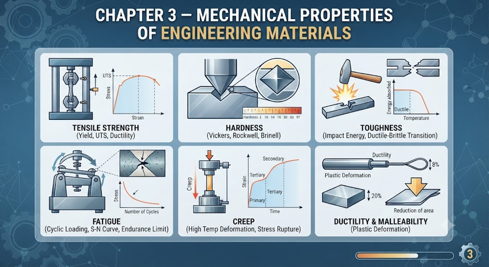
3.1 Introduction
Mechanical properties describe how an engineering material behaves when subjected to an external force or load.
For Workshop Technology, understanding these properties is important because the selection of material for a machine component depends heavily on its mechanical behaviour.
For example:
A shaft requires adequate strength and toughness.
A spring requires high resilience and fatigue strength.
A cutting tool requires high hardness and wear resistance.
A wire requires good ductility.
A sheet-metal component requires good malleability and formability.
A machine bed benefits from good stiffness and vibration damping.
3.2 Load
Definition
A load is an external force or system of forces acting on a body.
Common Types of Loading
Tensile load
Compressive load
Shear load
Bending load
Torsional load
3.3 Tensile Load
A tensile load tends to pull a body apart.
Example
A rod being pulled from both ends is subjected to tensile loading.
Effect: Increase in length and reduction in cross-sectional dimensions.
3.4 Compressive Load
A compressive load tends to shorten or compress a body.
Example
A column carrying a vertical load is subjected primarily to compression.
Effect: Reduction in length and possible increase in lateral dimensions.
3.5 Shear Load
A shear load tends to cause one part of a body to slide relative to another part.
Example
A rivet or bolt subjected to transverse loading can experience shear.
3.6 Bending Load
A bending load causes a component to curve or bend.
Examples
Beams
Shafts
Levers
Machine components
A bending load can produce both tensile and compressive stresses in different regions of a component.
3.7 Torsional Load
A torsional load produces twisting about the longitudinal axis of a component.
Examples
Shafts
Drive axles
Transmission components
3.8 Stress
Definition
Stress is the internal resisting force developed per unit area of a material when an external load is applied.
For normal stress:
σ=P/A
Where:
σ= stress
P= applied load
A= cross-sectional area
SI Unit
Pascal (Pa)
In engineering applications, MPa and N/mm² are commonly used.
Important Relation
1″ ” N/mm^2=1″ ” MPa
3.9 Tensile Stress
Tensile stress is produced when a member is subjected to a tensile load.
σ_t=P/A
It tends to elongate the material.
3.10 Compressive Stress
Compressive stress is produced when a member is subjected to compressive loading.
σ_c=P/A
It tends to shorten the member.
3.11 Shear Stress
Shear stress acts tangentially to a surface and tends to cause sliding between adjacent layers.
It is commonly represented by:
τ=P/A
for the simple average shear-stress case.
3.12 Strain
Definition
Strain is the deformation produced per unit original dimension.
For linear tensile strain:
ϵ=ΔL/L
Where:
ΔL= change in length
L= original length
Important Point
Strain has no unit because it is a ratio of two lengths.
3.13 Tensile Strain
Tensile strain is produced when a material is subjected to tensile stress.
ϵ_t=”Increase in length” /”Original length”
3.14 Compressive Strain
Compressive strain is produced when a material is subjected to compressive stress.
ϵ_c=”Decrease in length” /”Original length”
3.15 Hooke’s Law
Definition
Hooke’s Law states that, within the elastic limit, stress is directly proportional to strain.
σ∝ϵ
Therefore:
σ=Eϵ
where Eis Young’s modulus.
Important Condition
Hooke’s law is applicable only within the proportional/elastic range as appropriate to the material and loading condition.
3.16 Young’s Modulus
Young’s modulus is the ratio of normal stress to corresponding normal strain within the linear elastic region.
E=σ/ϵ
SI Unit
Pa or N/m²
In engineering:
GPa is commonly used.
Important Point
A higher Young’s modulus generally indicates a stiffer material in axial loading.
3.17 Modulus of Rigidity
The modulus of rigidity, also called shear modulus, is the ratio of shear stress to shear strain within the elastic range.
G=τ/γ
where:
G= modulus of rigidity
τ= shear stress
γ= shear strain
3.18 Bulk Modulus
The bulk modulus is the ratio of hydrostatic pressure to the corresponding volumetric strain.
K=p/(ΔV/V)
It represents resistance to uniform volumetric deformation.
3.19 Poisson’s Ratio
Definition
Poisson’s ratio is the ratio of lateral strain to longitudinal strain in a material under axial loading, with sign convention depending on the formulation.
In magnitude form:
ν=”lateral strain” /”longitudinal strain”
Because a tensile-loaded specimen generally becomes narrower laterally, the signed lateral strain is opposite in sign to the longitudinal strain.
3.20 Elastic Limit
Definition
The elastic limit is the maximum stress up to which a material can return essentially to its original dimensions after removal of the load.
Beyond this region, permanent deformation may remain.
3.21 Proportional Limit
Definition
The proportional limit is the highest stress up to which stress remains directly proportional to strain.
Difference
Proportional limit: stress-strain relationship remains linear.
Elastic limit: material can still substantially recover its original dimensions after unloading.
The two limits may be very close for many engineering materials, but they are conceptually different.
3.22 Yield Point
Definition
The yield point is the stress region at which significant plastic deformation begins without a corresponding large increase in stress, in materials that exhibit a distinct yield phenomenon.
Some materials do not show a sharply defined yield point; in such cases, an offset yield strength may be specified.
3.23 Yield Strength
Definition
Yield strength is the stress at which a specified amount of permanent/plastic deformation begins to be considered significant.
For many metals without a distinct yield point, a 0.2% proof stress is commonly used.
3.24 Ultimate Tensile Strength
Definition
Ultimate tensile strength (UTS) is the maximum engineering tensile stress reached by a specimen during a tensile test.
UTS=”Maximum load” /”Original cross-sectional area”
3.25 Fracture Stress
Fracture stress is the stress associated with the load at which the specimen finally fractures.
In an engineering stress-strain curve, fracture may occur after the ultimate tensile strength has been reached because of necking.
3.26 Plastic Deformation
Definition
Plastic deformation is permanent deformation that remains after the external load is removed.
It occurs when the material is loaded beyond its elastic range.
3.27 Elastic Deformation
Definition
Elastic deformation is recoverable deformation that disappears when the load is removed, provided the material remains within its elastic range.
3.28 Ductility
Ductility is the ability of a material to undergo substantial plastic deformation in tension before fracture.
Common Measures
Percentage elongation
Percentage reduction in area
A higher percentage elongation generally indicates greater ductility.
3.29 Percentage Elongation
Percentage elongation is given by:
%” ” Elongation=(L_f-L_0)/L_0 ×100
Where:
L_0= original gauge length
L_f= final gauge length
3.30 Percentage Reduction in Area
%” ” Reduction” ” in” ” Area=(A_0-A_f)/A_0 ×100
Where:
A_0= original cross-sectional area
A_f= final cross-sectional area
It is also commonly used as an indicator of ductility.
3.31 Toughness
Definition
Toughness is the ability of a material to absorb energy and undergo plastic deformation before fracture.
Important Point
Toughness combines aspects of strength and ductility.
3.32 Resilience
Definition
Resilience is the ability of a material to absorb and store energy elastically.
Modulus of Resilience
The modulus of resilience represents the elastic strain energy absorbed per unit volume up to the elastic limit or relevant yield point.
3.33 Stiffness
Definition
Stiffness is the resistance offered by a body or material to deformation under load.
For axial loading, Young’s modulus is an important material parameter related to stiffness.
3.34 Hardness
Hardness is resistance to localized permanent deformation, commonly measured through indentation tests.
Common Tests
Brinell
Rockwell
Vickers
3.35 Rockwell Hardness Test
The Rockwell test determines hardness based on the depth of indentation produced under specified loading conditions.
Important Point
Rockwell testing is widely used because it is relatively rapid and does not require measuring the indentation diameter optically.
3.36 Brinell Hardness Test
The Brinell test uses a spherical indenter and determines hardness from the size of the indentation produced under a specified load.
Suitable For
It is often useful for relatively large or coarse-grained metallic specimens.
3.37 Vickers Hardness Test
The Vickers test uses a diamond pyramid indenter.
It is suitable for a wide range of materials and can be used for relatively small or thin specimens when appropriate testing conditions are selected.
3.38 Impact Strength
Definition
Impact strength represents the ability of a material to absorb energy under sudden or impact loading.
Common Tests
Charpy impact test
Izod impact test
3.39 Fatigue Strength
Definition
Fatigue strength is the ability of a material to withstand repeated or fluctuating stresses without failure for a specified number of cycles or under specified fatigue conditions.
3.40 Endurance Limit
For some materials, particularly certain steels, an endurance limit is the stress level below which the material can withstand a very large or effectively indefinite number of cycles under specified conditions.
Not all materials exhibit a true endurance limit.
3.41 Creep
Creep is the progressive, time-dependent deformation of a material under sustained stress.
It becomes especially important at elevated temperatures.
3.42 Wear
Wear is the progressive removal, displacement or degradation of material from a surface due to interaction with another surface or environment.
Major Types
Adhesive wear
Abrasive wear
Fatigue wear
Corrosive wear
3.43 Adhesive Wear
Adhesive wear occurs when material is transferred between contacting surfaces due to localized adhesion and subsequent shearing.
3.44 Abrasive Wear
Abrasive wear occurs when a hard surface or hard particles remove material from a softer surface.
3.45 Fatigue Wear
Fatigue wear occurs due to repeated loading and unloading of contacting surfaces, eventually causing surface damage and material removal.
3.46 Corrosive Wear
Corrosive wear occurs when chemical or electrochemical reactions contribute to material removal from a surface.
3.47 Factor of Safety
Definition
The factor of safety (FOS) provides a margin between the strength of a component/material and the allowable working condition.
A simplified form is:
FOS=”Failure strength” /”Allowable working stress”
The precise definition depends on the design criterion and material behavior.
Purpose
It accounts for uncertainties such as:
Variations in material properties
Manufacturing defects
Uncertainty in loading
Service conditions
Design assumptions
3.48 Working Stress
Definition
Working stress, or allowable stress, is the stress level permitted in a component during normal operation according to the applicable design standard and safety considerations.
3.49 Stress Concentration
Definition
Stress concentration is the localized increase in stress around discontinuities such as:
Holes
Notches
Sharp corners
Keyways
Grooves
Important Point
Sharp corners generally produce greater stress concentration than smoothly rounded transitions.
3.50 Engineering Stress vs True Stress
Engineering Stress
σ_e=P/A_0
where A_0is the original cross-sectional area.
True Stress
σ_t=P/A_i
where A_iis the instantaneous cross-sectional area.
Exam Point
Engineering stress uses the original area, while true stress uses the instantaneous area.
QUICK REVISION TABLE
Property/Term Meaning
Load External force/system of forces
Stress Internal force per unit area
Strain Deformation per unit original dimension
Tensile stress Stress due to pulling
Compressive stress Stress due to pushing
Shear stress Stress causing sliding
Young’s modulus Normal stress / normal strain
Shear modulus Shear stress / shear strain
Bulk modulus Hydrostatic stress / volumetric strain
Poisson’s ratio Lateral strain / longitudinal strain
Elasticity Recovery after unloading
Plasticity Permanent deformation
Yield strength Stress associated with specified plastic deformation
UTS Maximum engineering tensile stress
Ductility Plastic deformation in tension
Malleability Plastic deformation under compression
Toughness Energy absorption before fracture
Resilience Elastic energy absorption
Stiffness Resistance to deformation
Hardness Resistance to localized deformation
Fatigue Failure under repeated/fluctuating loading
Creep Time-dependent deformation
Wear Progressive surface/material loss
FOS Margin between failure and allowable condition
Stress concentration Localized increase in stress
IMPORTANT FORMULAS
Normal Stress
σ=P/A
Strain
ϵ=ΔL/L
Young’s Modulus
E=σ/ϵ
Shear Modulus
G=τ/γ
Percentage Elongation
%EL=(L_f-L_0)/L_0 ×100
Percentage Reduction in Area
%RA=(A_0-A_f)/A_0 ×100
Factor of Safety
FOS=”Failure strength” /”Allowable working stress”
Q1. The internal resisting force developed per unit area of a material subjected to an external load is called:
A. Strain
B. Stress
C. Deformation
D. Toughness
Answer: B. Stress
Explanation: Stress represents the internal resistance developed in a material against an applied load. For direct normal loading:
σ=P/A
Q2. The SI unit of stress is:
A. Newton
B. Joule
C. Pascal
D. Watt
Answer: C. Pascal
Explanation: Stress is force per unit area, so its SI unit is N/m², which is called the Pascal (Pa).
Q3. Which of the following is equivalent to 1 MPa?
A. 1 N/m²
B. 1 N/mm²
C. 1000 N/mm²
D. 1 kN/mm²
Answer: B. 1 N/mm²
Explanation:
1″ ” MPa=10^6 “ ” N/m^2=1″ ” N/mm^2
Q4. Strain is defined as:
A. Force per unit area
B. Deformation per unit original dimension
C. Force × distance
D. Energy per unit volume
Answer: B. Deformation per unit original dimension
Explanation: For linear deformation:
ϵ=ΔL/L
Therefore, strain is dimensionless.
Q5. The unit of strain is:
A. N
B. Pa
C. mm
D. No unit
Answer: D. No unit
Explanation: Strain is a ratio of two lengths and therefore has no physical unit.
Q6. A tensile load tends to:
A. Shorten a component
B. Twist a component only
C. Elongate a component
D. Produce no deformation
Answer: C. Elongate a component
Explanation: Tensile loading pulls a component apart and generally increases its length.
Q7. A compressive load tends to:
A. Increase length
B. Decrease length
C. Produce only twisting
D. Produce no stress
Answer: B. Decrease length
Explanation: Compressive loading tends to shorten a component.
Q8. A load acting tangentially to a surface primarily produces:
A. Tensile stress
B. Compressive stress
C. Shear stress
D. Hydrostatic stress
Answer: C. Shear stress
Explanation: Shear stress acts tangentially to the surface and tends to cause relative sliding between adjacent layers.
Q9. The ratio of normal stress to normal strain within the elastic range is:
A. Bulk modulus
B. Young’s modulus
C. Modulus of rigidity
D. Poisson’s ratio
Answer: B. Young’s modulus
Explanation:
E=σ/ϵ
Young’s modulus is an important measure of stiffness in axial loading.
Q10. The SI unit of Young’s modulus is:
A. N
B. N/m²
C. m/N
D. N·m
Answer: B. N/m²
Explanation: Since Young’s modulus is stress divided by dimensionless strain, its unit is the same as stress: Pa or N/m².
Q11. Hooke’s law states that, within the proportional limit:
A. Stress is inversely proportional to strain
B. Stress is directly proportional to strain
C. Stress is independent of strain
D. Strain is always zero
Answer: B. Stress is directly proportional to strain
Explanation:
σ∝ϵ
or
σ=Eϵ
within the applicable linear elastic range.
Q12. Which property indicates resistance to elastic deformation?
A. Stiffness
B. Ductility
C. Plasticity
D. Malleability
Answer: A. Stiffness
Explanation: Stiffness is the resistance offered by a material or component to elastic deformation.
Q13. A material that returns to its original shape after removal of load, within its elastic range, possesses:
A. Plasticity
B. Elasticity
C. Brittleness
D. Creep
Answer: B. Elasticity
Explanation: Elasticity is the ability of a material to recover its original shape and dimensions after the load is removed, provided the elastic range is not exceeded.
Q14. Permanent deformation remaining after removal of load is called:
A. Elastic deformation
B. Plastic deformation
C. Thermal deformation
D. Volumetric deformation only
Answer: B. Plastic deformation
Explanation: Plastic deformation is permanent deformation and does not disappear completely after unloading.
Q15. The maximum stress up to which a material substantially returns to its original dimensions after unloading is called:
A. Ultimate stress
B. Elastic limit
C. Breaking stress
D. Working stress
Answer: B. Elastic limit
Explanation: Beyond the elastic limit, permanent deformation can remain after the load is removed.
Q16. The maximum stress up to which stress is directly proportional to strain is called:
A. Proportional limit
B. Ultimate stress
C. Fracture stress
D. Breaking stress
Answer: A. Proportional limit
Explanation: Up to the proportional limit, stress and strain have a linear relationship.
Q17. The beginning of significant permanent deformation in a ductile material is associated with:
A. Yielding
B. Elastic recovery
C. Hardening only
D. Creep only
Answer: A. Yielding
Explanation: Yielding marks the transition from predominantly elastic behavior to significant plastic deformation.
Q18. Yield strength represents:
A. Stress at which specified plastic deformation occurs
B. Density of the material
C. Melting temperature
D. Thermal conductivity
Answer: A. Stress at which specified plastic deformation occurs
Explanation: For materials without a distinct yield point, a proof or offset yield strength, commonly 0.2%, may be specified.
Q19. The maximum engineering stress reached during a tensile test is called:
A. Yield stress
B. Ultimate tensile strength
C. Working stress
D. Shear stress
Answer: B. Ultimate tensile strength
Explanation: UTS is calculated using the maximum load divided by the original cross-sectional area.
UTS=P_max/A_0
Q20. Which property represents the ability of a material to undergo plastic deformation in tension before fracture?
A. Ductility
B. Hardness
C. Stiffness
D. Brittleness
Answer: A. Ductility
Explanation: Ductility indicates the capacity for plastic deformation under tensile loading.
Q21. Percentage elongation is commonly used as a measure of:
A. Hardness
B. Ductility
C. Stiffness
D. Thermal conductivity
Answer: B. Ductility
Explanation: A greater percentage elongation generally indicates greater ductility.
%EL=(L_f-L_0)/L_0 ×100
Q22. A material capable of being drawn into wires is generally:
A. Ductile
B. Brittle
C. Extremely hard and brittle
D. Non-metallic only
Answer: A. Ductile
Explanation: Wire drawing requires substantial tensile plastic deformation, which is characteristic of ductile materials.
Q23. The ability of a material to be formed into thin sheets by compressive deformation is:
A. Ductility
B. Malleability
C. Toughness
D. Resilience
Answer: B. Malleability
Explanation: Malleability refers particularly to plastic deformation under compressive loading.
Q24. Which property is most closely associated with resistance to indentation?
A. Hardness
B. Ductility
C. Resilience
D. Plasticity
Answer: A. Hardness
Explanation: Hardness is commonly evaluated through resistance to indentation.
Q25. Which of the following is a hardness test?
A. Brinell
B. Charpy
C. Izod
D. Tensile test
Answer: A. Brinell
Explanation: Brinell is a standard indentation hardness test.
Q26. The Rockwell hardness test primarily measures:
A. Indentation depth
B. Tensile elongation
C. Impact energy
D. Percentage reduction in area
Answer: A. Indentation depth
Explanation: Rockwell hardness is determined from the depth of indentation produced under specified loads.
Q27. The Vickers hardness test uses a:
A. Steel ball only
B. Diamond pyramid indenter
C. Cutting tool
D. Flat punch only
Answer: B. Diamond pyramid indenter
Explanation: The Vickers test uses a diamond pyramid, traditionally with a square base.
Q28. The Brinell hardness test commonly uses:
A. A spherical indenter
B. A diamond pyramid only
C. A sharp cutting tool
D. A cylindrical punch only
Answer: A. A spherical indenter
Explanation: Brinell hardness is determined from the indentation made by a spherical indenter.
Q29. Toughness is the ability of a material to:
A. Resist only indentation
B. Absorb energy before fracture
C. Conduct electricity
D. Conduct heat
Answer: B. Absorb energy before fracture
Explanation: Toughness represents the capacity to absorb mechanical energy before fracture.
Q30. Which property is particularly important for a component subjected to shock loading?
A. Toughness
B. Colour
C. Density only
D. Thermal expansion only
Answer: A. Toughness
Explanation: Tough materials can absorb significant energy before fracture and are therefore valuable under impact or shock loading.
Q31. Resilience refers to the ability of a material to:
A. Absorb energy elastically
B. Resist corrosion only
C. Resist melting
D. Undergo permanent deformation only
Answer: A. Absorb energy elastically
Explanation: Resilience is associated with elastic strain-energy storage.
Q32. A spring material should have high:
A. Resilience
B. Brittleness
C. Creep only
D. Thermal expansion
Answer: A. Resilience
Explanation: Springs store and release elastic energy, so high resilience is desirable.
Q33. Fatigue failure occurs mainly due to:
A. Repeated or fluctuating stresses
B. A single static load only
C. Melting
D. Corrosion only
Answer: A. Repeated or fluctuating stresses
Explanation: Fatigue is progressive damage caused by cyclic stress variations.
Q34. Which component is particularly susceptible to fatigue failure?
A. Rotating shaft
B. Stationary brick wall
C. Glass window with no loading
D. Wooden table under no load
Answer: A. Rotating shaft
Explanation: Rotating shafts can experience fluctuating bending and torsional stresses, making fatigue an important design consideration.
Q35. Creep is most significant when a component is subjected to:
A. Sustained load, particularly at elevated temperature
B. No load
C. Only one impact
D. Zero temperature
Answer: A. Sustained load, particularly at elevated temperature
Explanation: Creep is time-dependent deformation under sustained stress and becomes particularly important at elevated temperatures.
Q36. Which of the following is a typical creep-related application?
A. Steam turbine component
B. Hand file at room temperature only
C. Measuring scale
D. Wooden ruler
Answer: A. Steam turbine component
Explanation: Turbine components operate under sustained stress and elevated temperatures, making creep resistance important.
Q37. Wear is best described as:
A. Progressive material loss or surface degradation
B. Elastic recovery
C. Plastic elongation only
D. Increase in mass due to loading
Answer: A. Progressive material loss or surface degradation
Explanation: Wear occurs due to interaction between surfaces or with the environment and may involve material removal or displacement.
Q38. Abrasive wear occurs when:
A. Hard particles or surfaces remove material from a softer surface
B. A material melts completely
C. A component returns to its original shape
D. A material undergoes only elastic deformation
Answer: A. Hard particles or surfaces remove material from a softer surface
Explanation: Abrasive wear results from cutting, ploughing or scratching by harder asperities or particles.
Q39. Adhesive wear is associated with:
A. Material transfer between contacting surfaces
B. Only thermal expansion
C. Only elastic deformation
D. Absence of contact
Answer: A. Material transfer between contacting surfaces
Explanation: Localized adhesion between contacting surfaces can lead to material transfer and subsequent removal.
Q40. Which property is generally important for a cutting tool?
A. High hardness
B. Very low hardness
C. Very high malleability
D. Very low wear resistance
Answer: A. High hardness
Explanation: Cutting tools need adequate hardness and wear resistance to maintain their cutting edge.
Q41. A component has a load of 20,000 N and a cross-sectional area of 1,000 mm². The normal stress is:
A. 2 N/mm²
B. 20 N/mm²
C. 200 N/mm²
D. 20,000 N/mm²
Answer: B. 20 N/mm²
Explanation:
σ=P/A
=20,000/1,000=20″ ” N/mm^2
Therefore, stress = 20 MPa.
Numerical
Q42. A steel rod of original length 500 mm elongates by 1 mm. Its strain is:
A. 0.002
B. 0.02
C. 2
D. 500
Answer: A. 0.002
Explanation:
ϵ=ΔL/L
=1/500=0.002
Numerical
Q43. If the strain in a specimen is 0.005, the percentage strain is:
A. 0.05%
B. 0.5%
C. 5%
D. 50%
Answer: C. 0.5%
Explanation:
0.005×100=0.5%
Therefore, the correct answer is B. 0.5%.
Correction: The options contain the correct answer as B, not C.
Final Answer: B. 0.5%
Numerical
Q44. If stress is 200 MPa and strain is 0.001, Young’s modulus is:
A. 20 MPa
B. 200 MPa
C. 200 GPa
D. 2 GPa
Answer: C. 200 GPa
Explanation:
E=σ/ϵ
E=200/0.001=200,000″ ” MPa
Since:
1000″ ” MPa=1″ ” GPa
E=200″ ” GPa
Numerical
Q45. A rod has an original gauge length of 100 mm and final gauge length of 110 mm. Percentage elongation is:
A. 1%
B. 5%
C. 10%
D. 20%
Answer: C. 10%
Explanation:
%EL=(110-100)/100×100
=10%
Numerical
Q46. A specimen has an original cross-sectional area of 200 mm² and a final area of 150 mm². Percentage reduction in area is:
A. 10%
B. 20%
C. 25%
D. 50%
Answer: C. 25%
Explanation:
%RA=(200-150)/200×100
=50/200×100=25%
Numerical
Q47. If a material has a Young’s modulus of 200 GPa and is subjected to a stress of 100 MPa, its elastic strain is:
A. 0.0005
B. 0.005
C. 0.05
D. 0.5
Answer: A. 0.0005
Explanation:
ϵ=σ/E
Convert:
200″ ” GPa=200,000″ ” MPa
Therefore:
ϵ=100/200000=0.0005
Numerical
Q48. If the failure strength of a component is 600 MPa and its allowable stress is 150 MPa, the factor of safety is:
A. 2
B. 3
C. 4
D. 6
Answer: C. 4
Explanation:
FOS=600/150=4
Numerical
Q49. Which stress-strain region is associated with recoverable deformation?
A. Elastic region
B. Plastic region only
C. Fracture region
D. Necking region only
Answer: A. Elastic region
Explanation: Deformation within the elastic range is substantially recoverable after unloading.
Q50. In an engineering stress-strain curve for a ductile metal, necking generally begins after:
A. The proportional limit
B. The ultimate tensile strength
C. Zero stress
D. The origin
Answer: B. The ultimate tensile strength
Explanation: In a conventional tensile test of a ductile metal, localized necking generally begins after the maximum engineering stress, i.e., the UTS, has been reached.
Q51. Which modulus represents the ratio of shear stress to shear strain?
A. Young’s modulus
B. Bulk modulus
C. Modulus of rigidity
D. Resilience modulus
Answer: C. Modulus of rigidity
Explanation:
G=τ/γ
It is also called the shear modulus.
Q52. Which modulus represents resistance to uniform volumetric deformation?
A. Young’s modulus
B. Bulk modulus
C. Shear modulus
D. Section modulus
Answer: B. Bulk modulus
Explanation: Bulk modulus relates hydrostatic pressure to volumetric strain.
Q53. Poisson’s ratio relates:
A. Longitudinal stress and lateral stress
B. Lateral strain and longitudinal strain
C. Shear stress and normal stress
D. Load and area
Answer: B. Lateral strain and longitudinal strain
Explanation: Poisson’s ratio describes the lateral contraction/expansion associated with longitudinal deformation.
Q54. Which of the following is dimensionless?
A. Young’s modulus
B. Stress
C. Strain
D. Load
Answer: C. Strain
Explanation: Strain is a ratio of two dimensions of the same type and therefore has no unit.
Q55. The stress corresponding to the maximum engineering load in a tensile test is:
A. Yield stress
B. Ultimate tensile stress
C. Proof stress
D. Working stress
Answer: B. Ultimate tensile stress
Explanation: UTS is based on the maximum load divided by the original cross-sectional area.
Q56. Which property is generally associated with a brittle material?
A. Large plastic deformation before fracture
B. Little plastic deformation before fracture
C. Very high ductility
D. Very high malleability
Answer: B. Little plastic deformation before fracture
Explanation: Brittle materials generally fracture with little plastic deformation.
Q57. Which material property is desirable in a shaft subjected to shock loading?
A. Toughness
B. Brittleness
C. Low strength
D. Low fatigue resistance
Answer: A. Toughness
Explanation: Toughness allows a component to absorb significant energy before fracture.
Q58. Which property is especially important for a shaft under repeated rotational loading?
A. Fatigue strength
B. Colour
C. Density only
D. Melting point only
Answer: A. Fatigue strength
Explanation: Rotating shafts can experience cyclic stresses and therefore require adequate fatigue strength.
Q59. Which type of stress is mainly associated with a component subjected to twisting?
A. Tensile stress
B. Compressive stress
C. Shear stress
D. Hydrostatic stress
Answer: C. Shear stress
Explanation: Torsion primarily produces shear stresses in a shaft.
Q60. Which type of loading causes twisting of a shaft?
A. Tensile loading
B. Torsional loading
C. Compressive loading
D. Uniform pressure only
Answer: B. Torsional loading
Explanation: Torsional loading produces a twisting moment about the longitudinal axis.
Q61. Which type of load is primarily responsible for bending a beam?
A. Bending load
B. Torsional load only
C. Pure thermal load
D. Electrical load
Answer: A. Bending load
Explanation: Bending loading causes curvature of the beam and produces tensile and compressive stresses across its section.
Q62. A sharp corner in a machine component can cause:
A. Stress concentration
B. Zero stress
C. Zero deformation
D. Elimination of fatigue
Answer: A. Stress concentration
Explanation: Geometric discontinuities such as sharp corners, holes and keyways can cause localized increases in stress.
Q63. Which feature generally reduces stress concentration compared with a sharp corner?
A. Fillet radius
B. Sharp notch
C. Sudden section change
D. Crack
Answer: A. Fillet radius
Explanation: A smooth fillet reduces the severity of abrupt geometric changes and can lower stress concentration.
Q64. Engineering stress is calculated using:
A. Instantaneous area
B. Original cross-sectional area
C. Final area only
D. Surface area
Answer: B. Original cross-sectional area
Explanation:
σ_e=P/A_0
Engineering stress uses the original cross-sectional area.
Q65. True stress is calculated using:
A. Original area only
B. Instantaneous cross-sectional area
C. Gauge length only
D. Volume only
Answer: B. Instantaneous cross-sectional area
Explanation:
σ_t=P/A_i
where A_iis the instantaneous cross-sectional area.
Q66. A material with high Young’s modulus is generally:
A. More resistant to elastic deformation
B. More ductile in every case
C. More brittle in every case
D. Less stiff
Answer: A. More resistant to elastic deformation
Explanation: Higher Young’s modulus means greater stiffness for a given axial loading condition.
Q67. Young’s modulus primarily indicates:
A. Elastic stiffness
B. Corrosion resistance
C. Electrical conductivity
D. Melting point
Answer: A. Elastic stiffness
Explanation: Young’s modulus is a measure of resistance to elastic deformation in tension or compression.
Q68. Which of the following is NOT a mechanical property?
A. Toughness
B. Hardness
C. Ductility
D. Thermal conductivity
Answer: D. Thermal conductivity
Explanation: Thermal conductivity is a thermal property, while toughness, hardness and ductility are mechanical properties.
Q69. Which of the following is a mechanical property?
A. Ductility
B. Electrical conductivity
C. Thermal expansion
D. Density
Answer: A. Ductility
Explanation: Ductility describes mechanical behavior under loading.
Q70. Which test is commonly used to determine impact toughness?
A. Charpy test
B. Brinell test
C. Rockwell test
D. Vickers test
Answer: A. Charpy test
Explanation: Charpy and Izod are standard impact tests used to evaluate energy absorption under sudden loading.
Q71. The Izod test is used primarily to determine:
A. Impact toughness
B. Hardness
C. Young’s modulus
D. Thermal conductivity
Answer: A. Impact toughness
Explanation: Izod is an impact test in which a notched specimen is struck by a pendulum.
Q72. Which property is generally associated with the area under the complete engineering stress-strain curve up to fracture?
A. Toughness
B. Stiffness only
C. Hardness
D. Resilience only
Answer: A. Toughness
Explanation: The area under the complete stress-strain curve up to fracture represents the energy absorbed per unit volume, associated with toughness.
Q73. The area under the elastic portion of the stress-strain curve represents:
A. Modulus of resilience
B. Ultimate strength
C. Hardness
D. Fatigue strength
Answer: A. Modulus of resilience
Explanation: The elastic area represents elastic strain energy per unit volume.
Q74. Which property is particularly important for a material used in a forming operation?
A. Ductility/formability
B. Brittleness
C. Extremely low plasticity
D. Very low elongation
Answer: A. Ductility/formability
Explanation: Forming operations require sufficient plastic deformation without cracking.
Q75. Which material behavior is associated with permanent shape change?
A. Plasticity
B. Elasticity
C. Resilience
D. Stiffness
Answer: A. Plasticity
Explanation: Plasticity allows permanent deformation without immediate fracture.
Q76. Which property is important in a material used for a punch or die?
A. Hardness and wear resistance
B. Very low hardness
C. Very high malleability only
D. Low strength
Answer: A. Hardness and wear resistance
Explanation: Punches and dies are subjected to contact stresses and wear and therefore require suitable hardness and wear resistance.
Q77. Which of the following can cause premature fatigue failure?
A. Stress concentration
B. Smooth fillet
C. Proper surface finish
D. Correct material selection
Answer: A. Stress concentration
Explanation: Stress concentrations can significantly increase local cyclic stresses and promote fatigue crack initiation.
Q78. Which surface condition generally improves fatigue performance compared with a severely rough surface?
A. Smooth surface
B. Deep scratches
C. Sharp notches
D. Cracks
Answer: A. Smooth surface
Explanation: Surface defects and scratches can act as stress raisers and fatigue-crack initiation sites.
Q79. Which factor is important in creep?
A. Time
B. Time-independent load only
C. Colour
D. Electrical resistance only
Answer: A. Time
Explanation: Creep is fundamentally a time-dependent deformation process.
Q80. Which factor is especially important in high-temperature creep?
A. Temperature
B. Colour
C. Surface polish only
D. Electrical conductivity only
Answer: A. Temperature
Explanation: Creep rates generally increase strongly with temperature for many engineering materials.
Q81. A tensile specimen has an original length of 200 mm and elongates to 204 mm. Its percentage elongation is:
A. 1%
B. 2%
C. 4%
D. 20%
Answer: B. 2%
Explanation:
%EL=(204-200)/200×100
=2%
Numerical
Q82. A component carries 50 kN load over an area of 500 mm². Its average stress is:
A. 10 N/mm²
B. 50 N/mm²
C. 100 N/mm²
D. 500 N/mm²
Answer: C. 100 N/mm²
Explanation:
σ=50,000/500=100″ ” N/mm^2
Therefore, stress = 100 MPa.
Numerical
Q83. A rod of 2 m length elongates by 2 mm. The strain is:
A. 0.001
B. 0.01
C. 0.1
D. 1
Answer: A. 0.001
Explanation:
Convert 2 m to 2000 mm.
ϵ=2/2000=0.001
Numerical
Q84. If Young’s modulus is 210 GPa and the strain is 0.001, the stress is:
A. 21 MPa
B. 210 MPa
C. 2.1 MPa
D. 2100 MPa
Answer: B. 210 MPa
Explanation:
σ=Eϵ
=210×0.001=0.210″ ” GPa
=210″ ” MPa
Numerical
Q85. A material has a failure strength of 800 MPa and a factor of safety of 4. Its allowable stress is:
A. 100 MPa
B. 200 MPa
C. 400 MPa
D. 3200 MPa
Answer: B. 200 MPa
Explanation:
FOS=(Failure” ” strength)/(Allowable” ” stress)
Therefore:
Allowable” ” stress=800/4=200″ ” MPa
Numerical
Q86. A specimen has an original area of 400 mm² and final area of 300 mm². The percentage reduction in area is:
A. 10%
B. 20%
C. 25%
D. 40%
Answer: C. 25%
Explanation:
%RA=(400-300)/400×100
=25%
Numerical
Q87. If the original length of a specimen is 250 mm and the final length is 275 mm, percentage elongation is:
A. 5%
B. 10%
C. 15%
D. 25%
Answer: B. 10%
Explanation:
%EL=(275-250)/250×100=10%
Numerical
Q88. A stress of 150 MPa produces a strain of 0.00075 in a linearly elastic material. Young’s modulus is:
A. 100 GPa
B. 150 GPa
C. 200 GPa
D. 250 GPa
Answer: C. 200 GPa
Explanation:
E=σ/ϵ
=150/0.00075=200,000″ ” MPa=200″ ” GPa
Numerical
Q89. Which of the following statements about ductility is correct?
A. It is measured only by hardness
B. Percentage elongation can be used as an indicator of ductility
C. It means resistance to indentation
D. It means resistance to creep only
Answer: B. Percentage elongation can be used as an indicator of ductility
Explanation: Percentage elongation and percentage reduction in area are commonly used measures of ductility.
Q90. Which of the following statements about toughness is correct?
A. Toughness is identical to hardness
B. Toughness concerns energy absorption before fracture
C. Toughness means only electrical conductivity
D. Toughness means zero deformation
Answer: B. Toughness concerns energy absorption before fracture
Explanation: Toughness represents the capacity to absorb energy and deform before fracture.
Q91. Which of the following statements about hardness is correct?
A. Hardness is resistance to localized deformation
B. Hardness means ductility
C. Hardness means elastic recovery only
D. Hardness means creep rate
Answer: A. Hardness is resistance to localized deformation
Explanation: Indentation hardness tests measure resistance to localized permanent deformation.
Q92. Which statement about fatigue is correct?
A. Fatigue can occur under repeated stresses
B. Fatigue occurs only above the melting point
C. Fatigue is identical to creep
D. Fatigue occurs only under static loading
Answer: A. Fatigue can occur under repeated stresses
Explanation: Fatigue is progressive damage resulting from cyclic or fluctuating stresses.
Q93. Which statement about creep is correct?
A. It is time-dependent deformation
B. It is always instantaneous
C. It is identical to hardness
D. It requires no load
Answer: A. It is time-dependent deformation
Explanation: Creep is the progressive deformation of a material with time under sustained stress, especially at elevated temperature.
Q94. Which property is most desirable for a material used in a cable or wire?
A. Ductility
B. Brittleness
C. Very low tensile strength
D. Very high brittleness
Answer: A. Ductility
Explanation: Wire manufacturing involves drawing, which requires substantial plastic deformation without fracture.
Q95. Which property is particularly desirable in a material used for pressure vessels?
A. Adequate strength and toughness
B. Extreme brittleness
C. Very low ductility
D. Zero fatigue resistance
Answer: A. Adequate strength and toughness
Explanation: Pressure vessels must safely withstand pressure and potential service loads without catastrophic fracture.
Q96. Which property is particularly important for a machine bed?
A. Stiffness
B. Extreme ductility
C. High malleability only
D. Low strength
Answer: A. Stiffness
Explanation: Machine beds must resist deformation and maintain alignment during operation.
Q97. Which of the following is a common cause of stress concentration?
A. Keyway
B. Smooth uniform section
C. Large fillet radius
D. Uniform straight surface
Answer: A. Keyway
Explanation: Keyways create geometric discontinuities and can produce local stress concentration.
Q98. Which of the following is generally used to reduce stress concentration?
A. Sharp notch
B. Fillet
C. Crack
D. Sudden section change
Answer: B. Fillet
Explanation: A properly designed fillet provides a smoother transition and reduces the severity of stress concentration.
Q99. Which statement correctly distinguishes elasticity and plasticity?
A. Elasticity produces permanent deformation; plasticity produces recovery
B. Elasticity is recoverable deformation; plasticity is permanent deformation
C. Both mean exactly the same thing
D. Neither involves deformation
Answer: B. Elasticity is recoverable deformation; plasticity is permanent deformation
Explanation: Elastic deformation disappears substantially after unloading, while plastic deformation remains.
Q100. Which combination is correctly matched?
A. Ductility — ability to absorb impact energy only
B. Hardness — resistance to indentation
C. Creep — repeated cyclic loading only
D. Fatigue — time-dependent deformation under sustained load
Answer: B. Hardness — resistance to indentation
Explanation: Hardness is associated with resistance to localized deformation such as indentation. Fatigue concerns cyclic loading, while creep is time-dependent deformation under sustained stress.
CHAPTER 3 — EXAM REVISION BOX
⭐ Remember These
Stress = Load / Area
Strain = Change in dimension / Original dimension
Young’s Modulus = Stress / Strain
Ductility → Wire drawing
Malleability → Sheet forming
Hardness → Indentation resistance
Toughness → Energy absorption before fracture
Resilience → Elastic energy absorption
Stiffness → Resistance to elastic deformation
Fatigue → Repeated/fluctuating stress
Creep → Time-dependent deformation
Brinell → Ball indenter
Rockwell → Indentation depth
Vickers → Diamond pyramid
Charpy/Izod → Impact testing
Stress concentration → Holes, keyways, notches, sharp corners
CHAPTER 4 — METAL TESTING & TESTING MACHINES
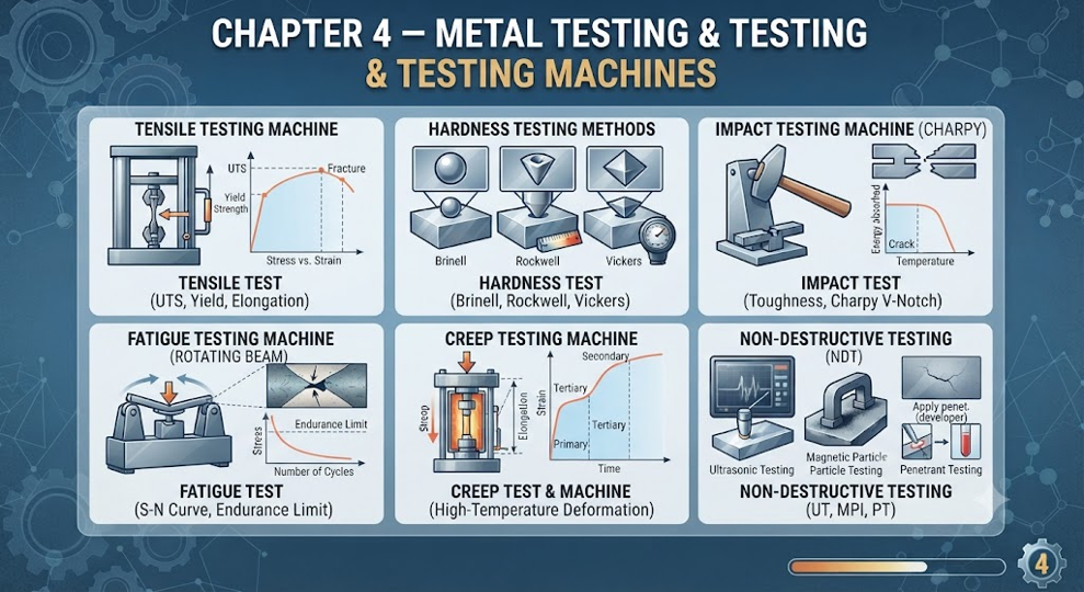
4.1 Introduction
Metal testing is the systematic examination of metals and engineering materials to determine their mechanical properties, physical characteristics, defects, quality and suitability for a particular application.
In Workshop Technology and Manufacturing Processes, testing is important because the material selected for a component must be capable of safely performing under the expected service conditions.
For example:
Shafts → tensile, torsion and fatigue considerations
Pressure vessels → tensile, toughness and NDT
Gears → hardness, wear and fatigue
Springs → tensile, fatigue and resilience
Welded components → tensile and NDT
Machine tools → hardness, strength and dimensional accuracy
4.2 Classification of Material Tests
Material testing can broadly be classified into:
- Destructive Testing (DT)
In destructive testing, the specimen is damaged or destroyed during the test.
Examples:
Tensile test
Compression test
Impact test
Torsion test
Fatigue test
Bend test - Non-Destructive Testing (NDT)
In NDT, the component is inspected without causing significant damage to its serviceability.
Examples:
Visual testing
Liquid penetrant testing
Magnetic particle testing
Ultrasonic testing
Radiographic testing
4.3 Destructive Testing
Definition
A destructive test is a test in which the specimen undergoes permanent deformation, damage or fracture during testing.
Main Purpose
To determine properties such as:
Yield strength
Ultimate tensile strength
Ductility
Toughness
Elongation
Reduction in area
Fatigue behaviour
4.4 Non-Destructive Testing
Definition
Non-destructive testing (NDT) is a group of inspection methods used to detect surface or internal discontinuities without significantly damaging the component.
Advantages
Component can often remain in service
Defects can be detected without destroying the part
Useful for quality control
Useful for weld inspection
Useful for detecting hidden defects
4.5 Tensile Test
The tensile test is one of the most important mechanical tests performed on engineering materials.
It determines properties such as:
Yield strength
Ultimate tensile strength
Percentage elongation
Percentage reduction in area
Young’s modulus, within the appropriate elastic range
4.6 Universal Testing Machine
A Universal Testing Machine (UTM) is a machine used to perform several mechanical tests by applying controlled loads to specimens.
Depending on its configuration, a UTM can be used for:
Tensile testing
Compression testing
Bending testing
Shear testing
The machine generally includes:
Loading system
Grips/fixtures
Load-measuring system
Specimen holding arrangement
Control and recording system
4.7 Tensile Test Specimen
A standard tensile specimen generally consists of:
Grip ends
Gauge length
Reduced section
The reduced section is intended to provide a controlled region in which deformation occurs.
4.8 Gauge Length
Definition
The gauge length is the specified length over which elongation is measured during a tensile test.
Initial gauge length is usually represented by:
L_0
Final gauge length after fracture is represented by:
L_f
4.9 Tensile Test Results
A tensile test can provide:
- Yield strength
Stress associated with the onset of specified plastic deformation. - Ultimate tensile strength
Maximum engineering tensile stress. - Percentage elongation
%EL=(L_f-L_0)/L_0 ×100 - Percentage reduction in area
%RA=(A_0-A_f)/A_0 ×100
4.10 Engineering Stress-Strain Curve
A typical tensile test produces an engineering stress-strain curve.
Important regions/points include:
Proportional limit
Elastic limit
Yield region
Strain-hardening region
Ultimate tensile strength
Necking
Fracture
The exact appearance varies with the material.
4.11 Proportional Region
In the proportional region:
σ∝ϵ
Therefore:
σ=Eϵ
The slope of the linear portion of the engineering stress-strain curve represents Young’s modulus.
4.12 Yielding
Yielding represents the onset of significant plastic deformation.
Some materials, particularly certain low-carbon steels under appropriate conditions, may show a distinct upper and lower yield point.
Other materials do not show a sharply defined yield point
4.13 Strain Hardening
After yielding, some ductile metals become stronger as plastic deformation continues.
This phenomenon is called:
Strain hardening or work hardening.
4.14 Necking
After the maximum engineering stress is reached in a conventional tensile test of a ductile specimen, localized reduction in cross-sectional area may begin.
This is called:
Necking.
The specimen eventually fractures.
4.15 Compression Test
A compression test determines the behavior of a material under compressive loading.
It is particularly useful for materials such as:
Cast iron
Concrete
Ceramics
Certain polymers
Materials that are difficult to test in tension
Important Point
Ductile metals can undergo large compressive deformation without a clear fracture, making interpretation different from tensile testing.
4.16 Compression Testing Machine
A compression test may be performed using:
Universal Testing Machine
Dedicated compression testing machine
The specimen is placed between compression platens and subjected to increasing compressive load.
4.17 Compression Stress
Average compressive stress can be expressed as:
σ_c=P/A
where:
P= compressive load
A= relevant cross-sectional area
4.18 Shear Test
A shear test determines the resistance of a material to shear loading.
The basic average shear stress relationship is:
τ=P/A
depending on the test configuration.
Shear testing is useful for evaluating:
Riveted joints
Bolted joints
Welded joints
Pins
Fasteners
Materials subjected to direct shear
4.19 Torsion Test
The torsion test determines the behavior of a material under twisting.
It is especially important for:
Shafts
Axles
Drive components
Transmission elements
Important properties can include:
Torsional strength
Shear modulus
Angle of twist behavior
Torsional failure characteristics
4.20 Torsion Testing Machine
A torsion testing machine applies a controlled torque to a specimen and measures the resulting angular deformation.
The relationship between torque and angle of twist can be used to evaluate torsional behaviour.
4.21 Impact Test
Impact testing determines the ability of a material to absorb energy under sudden loading.
Two widely used impact tests are:
Charpy test
Izod test
4.22 Charpy Impact Test
In the Charpy test, a notched specimen is supported horizontally, and a pendulum strikes the specimen.
The absorbed impact energy is determined from the energy lost by the pendulum.
Key Point
Charpy → Horizontal specimen
4.23 Izod Impact Test
In the Izod test, the notched specimen is generally held vertically as a cantilever, and the pendulum strikes it.
Key Point
Izod → Vertical specimen
4.24 Importance of the Notch
A notch acts as a stress concentration.
The notch helps create a controlled location for crack initiation and allows comparison of the material’s resistance to impact fracture.
4.25 Impact Energy
Impact energy is the energy absorbed by the specimen during fracture under impact loading.
A higher absorbed impact energy generally indicates greater resistance to sudden fracture under the specified test conditions.
4.26 Hardness Testing
Hardness testing determines resistance to localized deformation, generally by indentation or related methods.
Major hardness tests include:
Brinell
Rockwell
Vickers
4.27 Brinell Hardness Test
The Brinell test uses a spherical indenter to produce an indentation.
The hardness number is related to the applied load and the size of the indentation.
Important
Brinell → Ball/Spherical indenter
4.28 Brinell Hardness Number
The Brinell hardness number is based on:
Applied load
Diameter of indenter
Diameter of indentation
The indentation diameter is measured after the test.
4.29 Advantages of Brinell Test
Suitable for many bulk metallic materials
Useful for relatively coarse or heterogeneous materials
Large indentation can provide a representative measurement
Limitation
The relatively large indentation may make the test unsuitable for very thin or finished surfaces where indentation damage is unacceptable.
4.30 Rockwell Hardness Test
The Rockwell test determines hardness from the depth of penetration of an indenter under specified loads.
Major Advantage
It is rapid and convenient for production inspection.
4.31 Rockwell Indenters
Depending on the Rockwell scale, indenters can include:
Diamond cone
Hardened steel ball
Carbide ball
The selected indenter and load depend on the particular Rockwell scale.
4.32 Vickers Hardness Test
The Vickers test uses a diamond pyramid indenter.
The two diagonals of the indentation are measured and used to determine the Vickers hardness value.
Important
Vickers → Diamond pyramid
4.33 Advantages of Vickers Test
Can be used over a wide hardness range
Suitable for small areas when properly prepared
Useful for thin sections and microhardness applications with suitable loads
Uses the same basic geometric indenter principle across its scales
4.34 Fatigue Test
Fatigue testing evaluates a material’s behavior under repeated or fluctuating stress.
The specimen is subjected to cyclic loading until:
Failure occurs, or
A specified number of cycles is reached.
4.35 S-N Curve
The relationship between cyclic stress amplitude and number of cycles to failure is commonly represented by an:
S-N curve
where:
S = stress amplitude
N = number of cycles to failure
It is also called a Wohler curve.
4.36 Fatigue Failure
Fatigue failure can occur at stress levels significantly below the static tensile strength.
Typical stages include:
Crack initiation
Crack propagation
Final fracture
4.37 Creep Test
A creep test determines the deformation of a material with time under sustained stress, usually at a controlled elevated temperature.
Important parameters include:
Stress
Temperature
Time
Strain
4.38 Creep Curve
A typical creep curve has three stages:
Stage I — Primary Creep
Creep rate decreases with time.
Stage II — Secondary Creep
Creep rate is approximately steady.
Stage III — Tertiary Creep
Creep rate accelerates, often leading to rupture.
4.39 Non-Destructive Testing — Major Methods
The major NDT methods are:
Visual Testing — VT
Liquid Penetrant Testing — PT
Magnetic Particle Testing — MT
Ultrasonic Testing — UT
Radiographic Testing — RT
4.40 Visual Testing
Visual testing is the simplest NDT method.
It can detect visible defects such as:
Surface cracks
Undercuts
Corrosion
Poor weld appearance
Dimensional abnormalities
4.41 Liquid Penetrant Testing
Liquid penetrant testing is used primarily for detecting surface-breaking discontinuities.
Basic Procedure
Clean the surface.
Apply penetrant.
Allow penetration time.
Remove excess penetrant.
Apply developer.
Inspect indications.
Important
It can be used on many non-porous materials, not only ferromagnetic materials.
4.42 Magnetic Particle Testing
Magnetic particle testing is used for detecting surface and near-surface discontinuities in ferromagnetic materials.
The component is magnetized and magnetic particles are applied.
Defects disturb the magnetic field and produce visible particle accumulations.
Important
MT → Ferromagnetic materials
4.43 Ultrasonic Testing
Ultrasonic testing uses high-frequency sound waves to detect internal and surface-connected discontinuities.
It can be used to detect:
Cracks
Inclusions
Lack of fusion
Internal discontinuities
Thickness variations
4.44 Principle of Ultrasonic Testing
An ultrasonic transducer sends high-frequency sound waves into the component.
When waves encounter an interface or discontinuity, part of the energy is reflected.
The reflected signal can be analyzed to determine information about the defect.
4.45 Radiographic Testing
Radiographic testing uses penetrating radiation, commonly X-rays or gamma rays, to produce an image showing internal variations in the component.
It is commonly used for inspection of:
Welds
Castings
Pressure-containing components
4.46 Advantages of Radiography
Radiography can reveal certain internal discontinuities and provides a permanent image/record when conventional film radiography is used.
Limitation
Radiographic testing involves radiation hazards and requires appropriate safety controls.
4.47 Selection of NDT Method
The appropriate NDT method depends on:
Material
Type of defect
Defect location
Component geometry
Thickness
Accessibility
Required sensitivity
Safety considerations
4.48 Weld Testing
Welds can be inspected using:
Visual testing
Liquid penetrant testing
Magnetic particle testing
Ultrasonic testing
Radiographic testing
The method selected depends on the weld material, geometry and suspected defect type.
4.49 Destructive vs Non-Destructive Testing
Destructive Testing Non-Destructive Testing
Specimen may be damaged/destroyed Component is generally preserved
Gives mechanical properties Mainly detects discontinuities
Tensile test Ultrasonic test
Compression test Radiography
Impact test Liquid penetrant
Torsion test Magnetic particle
Fatigue test Visual inspection
4.50 Key Examination Points
Remember:
Tensile Test → Strength + Ductility
UTM → Tensile/Compression/Bending and related tests
Charpy → Horizontal specimen
Izod → Vertical cantilever specimen
Brinell → Spherical indenter
Rockwell → Depth of indentation
Vickers → Diamond pyramid
Fatigue → Cyclic loading
S-N Curve → Stress vs Number of cycles
Creep → Time-dependent deformation
PT → Surface-breaking defects
MT → Ferromagnetic materials
UT → High-frequency sound waves
.
Q1. The main purpose of material testing is to determine:
A. Only colour
B. Mechanical properties and suitability
C. Only weight
D. Only electrical resistance
Answer: B. Mechanical properties and suitability
Explanation: Material testing helps determine properties and performance characteristics needed for engineering applications.
Q2. Which of the following is a destructive test?
A. Visual inspection
B. Tensile test
C. Ultrasonic test
D. Liquid penetrant test
Answer: B. Tensile test
Explanation: In a tensile test, the specimen is normally permanently deformed and eventually fractured.
Q3. Which is a non-destructive test?
A. Tensile test
B. Impact test
C. Ultrasonic testing
D. Compression test
Answer: C. Ultrasonic testing
Explanation: Ultrasonic testing detects discontinuities without significantly damaging the component.
Q4. A Universal Testing Machine can commonly perform:
A. Only hardness testing
B. Tensile and compression tests
C. Only chemical analysis
D. Only radiography
Answer: B. Tensile and compression tests
Explanation: A UTM can be configured for several mechanical tests including tensile, compression and bending tests.
Q5. The elongation of a tensile specimen is measured over its:
A. Head
B. Grip
C. Gauge length
D. Shoulder only
Answer: C. Gauge length
Explanation: Gauge length is the specified length over which elongation is measured.
Q6. The maximum engineering stress in a tensile test is called:
A. Yield strength
B. Ultimate tensile strength
C. Proof stress
D. Shear strength
Answer: B. Ultimate tensile strength
Explanation: UTS corresponds to the maximum engineering stress reached during the tensile test.
Q7. Which test is primarily used to determine impact toughness?
A. Charpy test
B. Brinell test
C. Vickers test
D. Rockwell test
Answer: A. Charpy test
Explanation: The Charpy test measures energy absorbed by a specimen under impact loading.
Q8. In the Charpy impact test, the specimen is generally:
A. Held vertically as a cantilever
B. Supported horizontally
C. Suspended freely
D. Rotated continuously
Answer: B. Supported horizontally
Explanation: A standard Charpy specimen is supported horizontally and struck by a pendulum.
Q9. In the Izod test, the specimen is generally:
A. Horizontally simply supported
B. Vertically supported as a cantilever
C. Freely suspended
D. Placed under compression
Answer: B. Vertically supported as a cantilever
Explanation: The Izod specimen is held vertically and struck by the pendulum.
Q10. The notch in an impact-test specimen mainly acts as:
A. A cooling device
B. A stress concentrator
C. A lubricant reservoir
D. A measuring scale
Answer: B. A stress concentrator
Explanation: The notch creates a controlled region of high local stress where fracture can initiate.
Q11. Brinell hardness testing uses:
A. A spherical indenter
B. A diamond cone only
C. A pendulum
D. Ultrasonic waves
Answer: A. A spherical indenter
Explanation: The Brinell method uses a ball-type indenter and measures the resulting indentation.
Q12. Rockwell hardness testing is primarily based on:
A. Indentation depth
B. Tensile elongation
C. Impact energy
D. Reduction in area
Answer: A. Indentation depth
Explanation: Rockwell hardness is determined from the depth of penetration under specified loading conditions.
Q13. The Vickers hardness test uses:
A. Steel ball
B. Diamond pyramid
C. Pendulum
D. Cylindrical roller
Answer: B. Diamond pyramid
Explanation: The Vickers indenter is a diamond pyramid, traditionally with a square base.
Q14. Which test is particularly suitable for determining hardness rapidly in production environments?
A. Rockwell test
B. Tensile test
C. Impact test
D. Creep test
Answer: A. Rockwell test
Explanation: Rockwell testing is relatively rapid because hardness is obtained directly from indentation depth.
Q15. Which test is commonly used for detecting surface-breaking cracks on a non-porous component?
A. Liquid penetrant testing
B. Tensile testing
C. Compression testing
D. Torsion testing
Answer: A. Liquid penetrant testing
Explanation: Penetrant testing is designed to reveal surface-breaking discontinuities in suitable non-porous materials.
Q16. Magnetic particle testing is primarily applicable to:
A. Ferromagnetic materials
B. All plastics
C. Wood only
D. Glass only
Answer: A. Ferromagnetic materials
Explanation: The method depends on magnetization and magnetic flux leakage.
Q17. Ultrasonic testing uses:
A. High-frequency sound waves
B. Visible light only
C. Magnetic particles only
D. X-rays only
Answer: A. High-frequency sound waves
Explanation: UT introduces high-frequency acoustic waves into the component and analyzes reflected signals.
Q18. Radiographic testing commonly uses:
A. X-rays or gamma rays
B. Water pressure
C. Magnetic particles
D. Mechanical indentation
Answer: A. X-rays or gamma rays
Explanation: Radiography uses penetrating radiation to produce an image showing internal variations.
Q19. Which NDT method is particularly useful for detecting internal discontinuities using reflected sound waves?
A. Ultrasonic testing
B. Visual testing
C. Liquid penetrant testing
D. Magnetic particle testing
Answer: A. Ultrasonic testing
Explanation: UT detects discontinuities through reflections of high-frequency sound waves.
Q20. The S-N curve is associated with:
A. Fatigue testing
B. Hardness testing
C. Compression testing
D. Brinell testing
Answer: A. Fatigue testing
Explanation: An S-N curve relates cyclic stress level to the number of cycles to failure
Q21. In an S-N curve, N generally represents:
A. Newton
B. Number of cycles
C. Normal stress
D. Notch depth
Answer: B. Number of cycles
Explanation: In fatigue testing, N represents the number of loading cycles.
Q22. Creep is:
A. Instantaneous elastic deformation only
B. Time-dependent deformation under sustained stress
C. Impact fracture only
D. Hardness measurement
Answer: B. Time-dependent deformation under sustained stress
Explanation: Creep develops progressively with time under sustained loading, particularly at elevated temperatures.
Q23. During secondary creep, the creep rate is approximately:
A. Constant
B. Infinite
C. Always zero
D. Increasing rapidly
Answer: A. Constant
Explanation: Secondary creep is characterized approximately by a steady creep rate.
Q24. During tertiary creep:
A. Creep rate generally accelerates
B. Creep stops completely
C. Stress becomes zero
D. The specimen becomes perfectly elastic
Answer: A. Creep rate generally accelerates
Explanation: Tertiary creep is associated with accelerating deformation and often culminates in rupture.
Q25. Which test determines a material’s behavior under twisting?
A. Torsion test
B. Brinell test
C. Charpy test
D. Radiographic test
Answer: A. Torsion test
Explanation: A torsion test applies torque and measures the resulting angular deformation and torsional response.
Q26. The tensile test is mainly performed to determine:
A. Melting point
B. Tensile properties
C. Electrical resistance
D. Thermal conductivity
Answer: B. Tensile properties
Explanation: A tensile test provides information about yield strength, ultimate tensile strength, elongation, reduction in area and elastic behavior.
Q27. Which property can be determined from the percentage elongation obtained in a tensile test?
A. Ductility
B. Hardness
C. Thermal conductivity
D. Density
Answer: A. Ductility
Explanation: Percentage elongation is one of the common measures of ductility.
Q28. The percentage reduction in area in a tensile test is calculated using:
A. Original and final cross-sectional areas
B. Original and final lengths
C. Load and time
D. Stress and temperature
Answer: A. Original and final cross-sectional areas
Explanation:
%RA=(A_0-A_f)/A_0 ×100
where A_0is the original area and A_fis the final area.
Q29. The slope of the initial straight portion of a stress-strain curve represents:
A. Toughness
B. Young’s modulus
C. Hardness
D. Fatigue strength
Answer: B. Young’s modulus
Explanation: In the linear elastic region:
E=σ/ϵ
Thus, the slope is Young’s modulus.
Q30. In a tensile test of a ductile metal, necking normally begins:
A. Before loading
B. At or after the maximum engineering stress
C. At zero stress
D. Before the elastic region
Answer: B. At or after the maximum engineering stress
Explanation: Localized necking generally begins after the maximum engineering stress, i.e., after UTS has been reached.
Q31. Which machine is commonly used for tensile testing of metallic specimens?
A. Universal Testing Machine
B. Lathe machine
C. Drilling machine
D. Shaper
Answer: A. Universal Testing Machine
Explanation: A UTM is designed to apply controlled loads for tests such as tension and compression.
Q32. The load applied during a tensile test is measured by the:
A. Load-measuring system of the testing machine
B. Vernier caliper
C. Micrometer only
D. Thermometer
Answer: A. Load-measuring system of the testing machine
Explanation: The testing machine incorporates a load cell or other calibrated load-measuring mechanism.
Q33. A tensile specimen normally has a reduced section mainly to:
A. Control the region of deformation
B. Increase its weight
C. Prevent any deformation
D. Increase its temperature
Answer: A. Control the region of deformation
Explanation: The reduced gauge section promotes deformation in a defined region and facilitates measurement.
Q34. Which of the following is NOT normally obtained directly from a tensile test?
A. Ultimate tensile strength
B. Percentage elongation
C. Reduction in area
D. Melting point
Answer: D. Melting point
Explanation: Melting point is a thermal property and is not determined by a standard tensile test.
Q35. The area under the complete stress-strain curve up to fracture is associated with:
A. Toughness
B. Hardness
C. Stiffness only
D. Yield strength only
Answer: A. Toughness
Explanation: It represents the energy absorbed per unit volume before fracture.
Q36. The area under the elastic portion of the stress-strain curve represents:
A. Modulus of resilience
B. Ultimate strength
C. Hardness number
D. Fatigue limit
Answer: A. Modulus of resilience
Explanation: The area under the elastic region represents elastic strain energy stored per unit volume.
Q37. A material that undergoes considerable plastic deformation before fracture is:
A. Ductile
B. Brittle
C. Perfectly rigid
D. Non-deformable
Answer: A. Ductile
Explanation: Ductility is the ability to undergo significant plastic deformation in tension before fracture.
Q38. A brittle material generally shows:
A. Large plastic deformation before fracture
B. Little plastic deformation before fracture
C. Unlimited elongation
D. No fracture
Answer: B. Little plastic deformation before fracture
Explanation: Brittle materials generally fracture with relatively little plastic deformation.
Q39. Compression testing is particularly useful for evaluating:
A. Compressive behavior
B. Electrical conductivity
C. Melting temperature
D. Magnetic permeability only
Answer: A. Compressive behavior
Explanation: Compression tests evaluate the response of a material to compressive loading.
Q40. Which material is commonly evaluated by compression testing because tensile testing may be less representative of its service behavior?
A. Concrete
B. Copper wire only
C. Spring wire only
D. Aluminium foil only
Answer: A. Concrete
Explanation: Concrete has high compressive strength but comparatively low tensile strength, making compression testing particularly important.
Q41. A specimen under compression generally experiences:
A. Reduction in length
B. Increase in length
C. Only twisting
D. No deformation
Answer: A. Reduction in length
Explanation: Compressive loading tends to shorten the specimen.
Q42. The primary purpose of a torsion test is to determine:
A. Behavior under twisting
B. Resistance to indentation
C. Impact energy
D. Thermal expansion
Answer: A. Behavior under twisting
Explanation: Torsion testing determines the response of a material to applied torque.
Q43. Torsion testing is particularly important for:
A. Shafts
B. Flat glass windows
C. Bricks only
D. Paint coatings only
Answer: A. Shafts
Explanation: Shafts transmit torque and therefore must have adequate torsional strength and stiffness.
Q44. The angle through which a torsion specimen rotates under applied torque is called:
A. Angle of twist
B. Angle of friction
C. Angle of impact
D. Angle of hardness
Answer: A. Angle of twist
Explanation: The angular deformation caused by torque is called the angle of twist.
Q45. The main objective of an impact test is to determine:
A. Energy absorption under sudden loading
B. Melting point
C. Thermal conductivity
D. Electrical resistance
Answer: A. Energy absorption under sudden loading
Explanation: Impact tests evaluate resistance to fracture under sudden loading.
Q46. Which of the following is an impact testing machine/test?
A. Charpy
B. Brinell
C. Rockwell
D. Vickers
Answer: A. Charpy
Explanation: Charpy is an impact test, whereas Brinell, Rockwell and Vickers are hardness tests.
Q47. Which pair consists entirely of impact tests?
A. Charpy and Izod
B. Brinell and Vickers
C. Rockwell and Brinell
D. Vickers and Izod
Answer: A. Charpy and Izod
Explanation: Both Charpy and Izod are pendulum impact tests.
Q48. In a Charpy test, the specimen is generally:
A. Simply supported
B. Held as a vertical cantilever
C. Clamped at both ends
D. Held without support
Answer: A. Simply supported
Explanation: A standard Charpy specimen rests horizontally on supports and is struck by the pendulum.
Q49. In an Izod test, the specimen is:
A. Held as a cantilever
B. Simply supported at both ends
C. Freely suspended
D. Placed horizontally without support
Answer: A. Held as a cantilever
Explanation: The Izod specimen is fixed vertically at one end.
Q50. The energy absorbed by an impact specimen is determined from:
A. Loss of pendulum energy
B. Change in colour
C. Increase in temperature only
D. Weight of the specimen alone
Answer: A. Loss of pendulum energy
Explanation: The difference between the pendulum’s energy before and after striking the specimen corresponds to the energy absorbed, accounting for machine losses as applicable.
Q51. Which hardness test uses the diameter of an indentation as an important measurement?
A. Brinell
B. Rockwell
C. Ultrasonic
D. Radiographic
Answer: A. Brinell
Explanation: Brinell hardness is determined from the load and the diameter of the indentation produced by the spherical indenter.
Q52. In the Rockwell test, the hardness value is mainly related to:
A. Depth of penetration
B. Pendulum height
C. Specimen elongation
D. Reduction in area
Answer: A. Depth of penetration
Explanation: Rockwell hardness is based on indentation depth under specified minor and major loads.
Q53. The Vickers hardness number is determined from:
A. Indentation diagonals and applied load
B. Tensile elongation only
C. Impact energy only
D. Pendulum velocity only
Answer: A. Indentation diagonals and applied load
Explanation: The Vickers test measures the diagonals of the diamond-pyramid indentation.
Q54. Which hardness test is particularly useful for very small areas when appropriate loads are selected?
A. Vickers
B. Charpy
C. Izod
D. Compression
Answer: A. Vickers
Explanation: Vickers testing can be performed with relatively small loads and is widely used in microhardness applications.
Q55. Which of the following is a major advantage of Rockwell hardness testing?
A. Rapid measurement
B. Requires complete fracture
C. Requires tensile specimen
D. Measures impact energy
Answer: A. Rapid measurement
Explanation: Rockwell testing is widely used for quick production inspection.
Q56. Fatigue testing involves:
A. Repeated or fluctuating loading
B. Only one static load
C. Only thermal loading
D. Only hydrostatic pressure
Answer: A. Repeated or fluctuating loading
Explanation: Fatigue damage develops under cyclic stress variations.
Q57. Fatigue failure can occur:
A. Only above UTS
B. At stress levels below static tensile strength
C. Only at melting temperature
D. Only under compression
Answer: B. At stress levels below static tensile strength
Explanation: Repeated loading can initiate and propagate cracks even when individual stress cycles are below the material’s static strength.
Q58. A fatigue crack usually begins at:
A. A region of stress concentration or surface defect
B. The centre of a perfectly uniform specimen only
C. A region of zero stress
D. The measuring scale
Answer: A. A region of stress concentration or surface defect
Explanation: Notches, scratches, holes and other discontinuities can promote fatigue crack initiation.
Q59. The S-N curve is also known as:
A. Wöhler curve
B. Brinell curve
C. Creep curve
D. Hardness curve
Answer: A. Wöhler curve
Explanation: The S-N relationship is historically associated with August Wöhler.
Q60. In an S-N curve, S generally represents:
A. Stress
B. Strain only
C. Surface area
D. Speed
Answer: A. Stress
Explanation: S represents the selected cyclic stress measure, commonly stress amplitude.
Q61. Which test is used to study time-dependent deformation?
A. Creep test
B. Brinell test
C. Charpy test
D. Tensile hardness test
Answer: A. Creep test
Explanation: Creep testing measures progressive deformation under sustained stress with time.
Q62. Creep is particularly important in:
A. High-temperature components
B. Components with no load
C. Room-temperature unloaded parts only
D. Measuring instruments only
Answer: A. High-temperature components
Explanation: Elevated temperature significantly accelerates creep in many engineering materials.
Q63. Which stage of creep has a decreasing creep rate?
A. Primary creep
B. Secondary creep
C. Tertiary creep
D. Fracture stage only
Answer: A. Primary creep
Explanation: During primary creep, the creep rate decreases with time.
Q64. Which stage of creep has approximately constant creep rate?
A. Primary
B. Secondary
C. Tertiary
D. Fracture
Answer: B. Secondary
Explanation: Secondary creep is characterized by an approximately steady-state creep rate.
Q65. Which stage of creep generally precedes rupture?
A. Tertiary creep
B. Primary creep
C. Elastic region
D. Proportional region
Answer: A. Tertiary creep
Explanation: Tertiary creep involves accelerating deformation and commonly ends in rupture.
Q66. Visual testing can detect:
A. Visible surface defects
B. Deep internal defects in every case
C. Atomic-level defects
D. All subsurface defects
Answer: A. Visible surface defects
Explanation: Visual inspection is mainly used for accessible surface conditions and visible discontinuities.
Q67. Liquid penetrant testing is primarily used to detect:
A. Surface-breaking discontinuities
B. Deep internal defects only
C. Bulk density
D. Young’s modulus
Answer: A. Surface-breaking discontinuities
Explanation: Penetrant enters surface-connected openings and is subsequently revealed by the developer.
Q68. The first important step in liquid penetrant testing is generally:
A. Surface cleaning
B. Applying developer immediately
C. Applying magnetic field
D. Fracturing the specimen
Answer: A. Surface cleaning
Explanation: The surface must be properly cleaned so the penetrant can enter relevant surface-breaking discontinuities.
Q69. In liquid penetrant testing, the developer is used to:
A. Draw penetrant out of discontinuities and make indications visible
B. Magnetize the component
C. Increase tensile strength
D. Produce a fracture
Answer: A. Draw penetrant out of discontinuities and make indications visible
Explanation: Developer creates a contrasting indication by drawing penetrant back to the surface.
Q70. Magnetic particle testing requires the test component to be:
A. Ferromagnetic
B. Transparent
C. Non-metallic only
D. Liquid
Answer: A. Ferromagnetic
Explanation: Magnetization and magnetic flux leakage are fundamental to this method.
Q71. A discontinuity in magnetic particle testing produces:
A. Magnetic flux leakage
B. Thermal expansion only
C. Sound absorption only
D. Electrical insulation only
Answer: A. Magnetic flux leakage
Explanation: A discontinuity disturbs the magnetic field, causing flux leakage where particles can accumulate.
Q72. Ultrasonic testing can be used to detect:
A. Internal discontinuities
B. Only colour variations
C. Only surface paint
D. Only electrical defects
Answer: A. Internal discontinuities
Explanation: Reflected ultrasonic waves can reveal internal defects and interfaces.
Q73. The device that sends and/or receives ultrasonic waves in UT is called:
A. Transducer
B. Pendulum
C. Indenter
D. Extensometer only
Answer: A. Transducer
Explanation: The transducer converts electrical energy to ultrasonic mechanical waves and receives returning signals.
Q74. Radiographic testing is particularly useful for:
A. Examining internal discontinuities
B. Measuring hardness directly
C. Measuring tensile strength directly
D. Measuring elongation directly
Answer: A. Examining internal discontinuities
Explanation: Radiography produces an image based on differential absorption of penetrating radiation.
Q75. Which radiation can be used in industrial radiographic testing?
A. X-rays
B. Visible light only
C. Sound waves
D. Radio waves only
Answer: A. X-rays
Explanation: Industrial radiography commonly uses X-rays and gamma radiation.
Q76. Which NDT method generally requires special radiation-safety precautions?
A. Radiographic testing
B. Visual testing
C. Liquid penetrant testing
D. Magnetic particle testing
Answer: A. Radiographic testing
Explanation: Ionizing radiation can be hazardous and requires controlled areas, shielding and appropriate safety procedures.
Q77. Which NDT method does NOT require the material to be ferromagnetic?
A. Liquid penetrant testing
B. Magnetic particle testing
C. Both require ferromagnetism
D. Neither can inspect metals
Answer: A. Liquid penetrant testing
Explanation: PT can be applied to many non-porous materials, whereas MT requires ferromagnetic material.
Q78. Which test is best associated with detecting surface cracks in a non-ferromagnetic, non-porous material?
A. Liquid penetrant test
B. Magnetic particle test
C. Brinell test
D. Compression test
Answer: A. Liquid penetrant test
Explanation: PT is suitable for surface-breaking defects in many non-porous materials, including non-ferromagnetic alloys.
Q79. Which method is especially useful for detecting subsurface defects in ferromagnetic components?
A. Magnetic particle testing
B. Visual testing only
C. Liquid penetrant only
D. Brinell testing
Answer: A. Magnetic particle testing
Explanation: MT can detect surface and certain near-surface discontinuities in ferromagnetic materials.
Q80. Which NDT method uses sound waves rather than electromagnetic radiation?
A. Ultrasonic testing
B. Radiography
C. Visual testing
D. Magnetic particle testing
Answer: A. Ultrasonic testing
Explanation: UT uses mechanical sound waves, generally at frequencies well above audible sound.
Q81. A steel specimen has an original gauge length of 100 mm and final gauge length of 120 mm. Percentage elongation is:
A. 10%
B. 20%
C. 25%
D. 30%
Answer: B. 20%
Explanation:
%EL=(120-100)/100×100=20%
Numerical
Q82. A specimen has an original area of 500 mm² and final area of 400 mm². Percentage reduction in area is:
A. 10%
B. 15%
C. 20%
D. 25%
Answer: C. 20%
Explanation:
%RA=(500-400)/500×100=20%
Numerical
Q83. A tensile specimen carries a load of 60 kN and has an original area of 300 mm². Engineering stress is:
A. 100 MPa
B. 150 MPa
C. 200 MPa
D. 300 MPa
Answer: C. 200 MPa
Explanation:
σ=(60,000)/300=200″ ” N/mm^2=200″ ” MPa
Numerical
Q84. A material has Young’s modulus of 200 GPa. If stress is 100 MPa, the elastic strain is:
A. 0.0005
B. 0.005
C. 0.05
D. 0.5
Answer: A. 0.0005
Explanation:
ϵ=σ/E=100/200000=0.0005
Numerical
Q85. If the maximum load during a tensile test is 50 kN and original area is 250 mm², UTS is:
A. 100 MPa
B. 150 MPa
C. 200 MPa
D. 250 MPa
Answer: C. 200 MPa
Explanation:
UTS=P_max/A_0
=(50,000)/250=200″ ” MPa
Numerical
Q86. A specimen’s original length is 250 mm and its final length is 275 mm. Percentage elongation is:
A. 5%
B. 10%
C. 15%
D. 20%
Answer: B. 10%
Explanation:
(275-250)/250×100=10%
Numerical
Q87. A specimen’s original area is 800 mm² and final area is 600 mm². Reduction in area is:
A. 10%
B. 20%
C. 25%
D. 30%
Answer: C. 25%
Explanation:
(800-600)/800×100=25%
Numerical
Q88. If the stress is 240 MPa and Young’s modulus is 120 GPa, the strain is:
A. 0.0002
B. 0.001
C. 0.002
D. 0.02
Answer: C. 0.002
Explanation:
120″ ” GPa=120000″ ” MPa
ϵ=240/120000=0.002
Numerical
Q89. A specimen has a final area of 90 mm² and an original area of 100 mm². Percentage reduction in area is:
A. 5%
B. 10%
C. 15%
D. 20%
Answer: B. 10%
Explanation:
(100-90)/100×100=10%
Numerical
Q90. A component has a failure strength of 500 MPa and allowable stress of 100 MPa. Factor of safety is:
A. 2
B. 3
C. 4
D. 5
Answer: D. 5
Explanation:
FOS=500/100=5
Numerical
Q91. Which testing method is most appropriate for determining ultimate tensile strength?
A. Tensile test
B. Brinell test
C. Radiographic test
D. Liquid penetrant test
Answer: A. Tensile test
Explanation: UTS is directly obtained from the maximum engineering stress in a tensile test.
Q92. Which test is primarily used to measure resistance to indentation?
A. Hardness test
B. Tensile test
C. Fatigue test
D. Creep test
Answer: A. Hardness test
Explanation: Hardness tests measure resistance to localized deformation, commonly through indentation.
Q93. Which combination is correctly matched?
A. Brinell — spherical indenter
B. Rockwell — pendulum
C. Charpy — diamond pyramid
D. Vickers — magnetic particles
Answer: A. Brinell — spherical indenter
Explanation: Brinell uses a spherical indenter; Rockwell uses depth measurement, Charpy is an impact test and Vickers uses a diamond pyramid.
Q94. Which combination is correctly matched?
A. Vickers — diamond pyramid
B. Charpy — hardness test
C. Izod — creep test
D. Rockwell — radiography
Answer: A. Vickers — diamond pyramid
Explanation: The Vickers test uses a diamond pyramid indenter.
Q95. Which combination is correctly matched?
A. S-N curve — fatigue
B. Creep curve — hardness
C. Brinell curve — tensile testing
D. Charpy curve — radiography
Answer: A. S-N curve — fatigue
Explanation: S-N curves describe the relationship between cyclic stress and number of cycles to failure.
Q96. Which combination is correctly matched?
A. PT — surface-breaking discontinuities
B. MT — all non-metallic materials
C. UT — indentation hardness
D. RT — tensile elongation
Answer: A. PT — surface-breaking discontinuities
Explanation: Liquid penetrant testing reveals surface-breaking discontinuities in suitable non-porous surfaces.
Q97. Which combination is correctly matched?
A. MT — ferromagnetic materials
B. UT — only transparent materials
C. RT — hardness measurement
D. PT — only ferromagnetic materials
Answer: A. MT — ferromagnetic materials
Explanation: Magnetic particle testing requires a material capable of being magnetized sufficiently for flux leakage to reveal discontinuities.
Q98. Which NDT technique can produce an image of internal discontinuities using penetrating radiation?
A. Radiographic testing
B. Visual testing
C. Magnetic particle testing
D. Liquid penetrant testing
Answer: A. Radiographic testing
Explanation: X-rays or gamma rays pass through the component and produce differential absorption that can reveal internal features.
Q99. Which NDT method uses reflected ultrasonic waves to locate discontinuities?
A. Ultrasonic testing
B. Brinell testing
C. Rockwell testing
D. Liquid penetrant testing
Answer: A. Ultrasonic testing
Explanation: UT evaluates reflected acoustic energy from interfaces and discontinuities.
Q100. Which statement is correct?
A. Destructive testing never damages the specimen
B. NDT is intended to inspect components without significant damage
C. Tensile testing is an NDT method
D. Charpy testing is a hardness test
Answer: B. NDT is intended to inspect components without significant damage
Explanation: NDT methods inspect materials/components while preserving their serviceability, subject to the particular method and inspection process.
CHAPTER 4 — QUICK REVISION
Test Main Purpose
Tensile Strength & ductility
Compression Compressive behavior
Shear Shear strength
Torsion Twisting behavior
Charpy Impact energy
Izod Impact energy
Brinell Hardness
Rockwell Hardness
Vickers Hardness
Fatigue Cyclic loading behavior
Creep Time-dependent deformation
VT Visible defects
PT Surface-breaking defects
MT Surface/near-surface defects in ferromagnetic materials
UT Internal discontinuities using sound waves
RT Internal discontinuities using X-rays/gamma rays
CHAPTER 5 — FOUNDRY TECHNOLOGY & CASTING PROCESSES
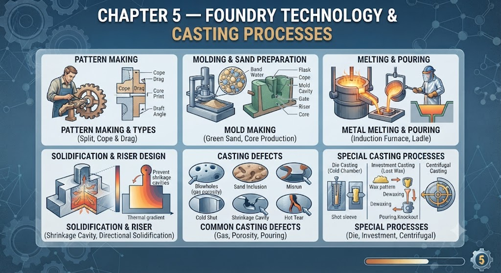
5.1 Introduction
Casting is one of the oldest and most important manufacturing processes. In casting, molten metal is poured into a prepared mould cavity having the desired shape. After solidification, the casting is removed from the mould and subjected to finishing operations.
Casting is particularly useful for producing:
Complex shapes
Large components
Components with internal cavities
Components that are difficult to manufacture by machining
Components from metals having relatively low machinability
Examples include:
Engine blocks
Cylinder heads
Pump housings
Machine beds
Pipes and pipe fittings
Flywheels
Gear blanks
Valve bodies
5.2 Definition of Casting
Casting is a manufacturing process in which molten material is introduced into a mould cavity of the required shape and allowed to solidify.
After solidification, the component is removed from the mould.
Basic Casting Sequence
Pattern → Mould → Melting → Pouring → Solidification → Shakeout → Fettling → Inspection
5.3 Basic Principle of Casting
The basic principle involves four major stages:
Step 1 — Preparation of mould
A cavity corresponding to the desired component is prepared.
Step 2 — Melting
The metal is heated above its melting temperature
Step 3 — Pouring
The molten metal is introduced into the mould cavity.
Step 4 — Solidification
The metal cools and solidifies, taking the shape of the mould cavity.
5.4 Advantages of Casting
Casting offers several important advantages.
- Complex shape
Very complex geometries can be produced. - Large components
Very large components can be manufactured economically. - Internal cavities
Cores can be used to produce internal holes and passages. - Wide material range
Many ferrous and non-ferrous alloys can be cast. - Reduced machining
Near-net-shape castings can reduce subsequent machining. - Economical for suitable production quantities
Casting can be economical for both certain small-batch and mass-production applications depending on the process.
5.5 Limitations of Casting
Some limitations include:
Possible casting defects
Porosity
Shrinkage
Gas defects
Dimensional variations
Surface-finish limitations in some processes
Mould preparation requirements
Metallurgical problems if cooling is not properly controlled
5.6 Classification of Casting Processes
Casting processes can broadly be classified into:
A. Expendable Mould Processes
The mould is normally destroyed to remove the casting.
Examples:
Sand casting
Shell moulding
Investment casting
Lost-foam casting
B. Permanent Mould Processes
The mould is reused for many castings.
Examples:
Gravity die casting
Pressure die casting
Centrifugal casting
5.7 Pattern
A pattern is a replica or representation of the desired casting shape used to form the mould cavity.
The pattern is not necessarily an exact-size replica because allowances may be provided.
5.8 Functions of a Pattern
A pattern is used to:
Produce the mould cavity
Establish the basic shape of the casting
Provide allowances
Provide core prints where required
Facilitate moulding
Help maintain dimensional accuracy
5.9 Pattern Materials
Patterns may be made from:
Wood
Metals
Plastics
Plaster
Wax
Resins
Other suitable materials
5.10 Wooden Patterns
Wood is commonly used for patterns because it is:
Lightweight
Relatively inexpensive
Easy to shape
Easy to repair
Easy to modify
Limitations
Wooden patterns can:
Absorb moisture
Warp
Wear relatively quickly
Require proper seasoning and surface treatment
5.11 Metal Patterns
Metal patterns are generally more durable than wooden patterns.
Common pattern metals include:
Aluminium alloys
Cast iron
Brass
Bronze
Steel
They are useful when:
Large numbers of castings are required
Better durability is needed
Better dimensional stability is required
5.12 Types of Patterns
Important pattern types include:
Single-piece pattern
Split pattern
Match-plate pattern
Cope-and-drag pattern
Loose-piece pattern
Sweep pattern
Skeleton pattern
Segmental pattern
Gated pattern
Follow-board pattern
5.13 Single-Piece Pattern
A single-piece pattern is made as one integral piece.
It is generally used for:
Simple shapes
Small production quantities
Components that can be easily withdrawn from the mould
5.14 Split Pattern
A split pattern consists of two or more parts.
The common two-part pattern is divided along a parting line.
Advantage
It facilitates withdrawal of the pattern from the mould without damaging the mould cavity.
5.15 Match-Plate Pattern
A match-plate pattern has the pattern halves mounted on opposite sides of a plate.
It is commonly used for:
High-production work
Machine moulding
Accurate mould alignment
5.16 Cope and Drag Pattern
In a cope-and-drag arrangement, pattern sections are mounted on separate plates.
It is useful for:
Large castings
Machine moulding
High-production applications
5.17 Sweep Pattern
A sweep pattern consists of a shaped board or template that is rotated around an axis to generate the mould cavity.
It is useful for:
Large circular or symmetrical castings
Large components where a complete pattern would be expensive
5.18 Skeleton Pattern
A skeleton pattern is a framework representing the shape of the casting.
It is generally used for:
Large castings
Simple geometries
Small production quantities
5.19 Gated Pattern
In a gated pattern, several patterns are connected to a common gating system.
This arrangement allows multiple castings to be produced in one mould.
5.20 Pattern Allowances
Pattern allowances are dimensional modifications provided on the pattern to compensate for various effects during casting and moulding.
Major allowances include:
Shrinkage allowance
Machining allowance
Draft allowance
Distortion allowance
Rapping/shake allowance
5.21 Shrinkage Allowance
Most metals shrink during cooling and solidification.
Therefore, the pattern is generally made slightly larger than the desired casting dimensions to compensate for shrinkage.
Important
Pattern size > corresponding final casting size
5.22 Machining Allowance
Additional material is provided on surfaces that will later be machined.
Purpose
It allows removal of:
Surface irregularities
Oxidized material
Dimensional variations
Casting skin
5.23 Draft Allowance
Draft is a small taper provided on vertical surfaces of the pattern.
Purpose
To facilitate easy withdrawal of the pattern from the mould without damaging the mould cavity.
Important
Draft → Easy pattern withdrawal
5.24 Distortion Allowance
Some castings may distort during cooling because different portions contract differently.
The pattern may therefore be intentionally distorted in the opposite direction to compensate.
5.25 Shake Allowance
When a pattern is rapped before removal, the mould cavity can become slightly enlarged.
Therefore, a small negative allowance may be considered to compensate for this effect.
5.26 Moulding Sand
Moulding sand is used to create the mould around the pattern.
Important requirements include:
Refractoriness
Permeability
Strength
Plasticity
Flowability
Collapsibility
Adhesiveness
Cohesiveness
5.27 Refractoriness
Refractoriness is the ability of moulding sand to withstand the high temperature of molten metal without melting or losing its essential properties.
Remember:
Refractoriness → Resistance to high temperature
5.28 Permeability
Permeability is the ability of moulding sand to allow gases and air to pass through it.
Adequate permeability is important for avoiding:
Blowholes
Gas porosity
Other gas-related defects
5.29 Cohesiveness
Cohesiveness is the ability of sand grains to stick to each other.
Good cohesiveness helps the mould retain its shape.
5.30 Adhesiveness
Adhesiveness is the ability of moulding sand to adhere to the surface of the moulding box or other supporting surfaces.
5.31 Plasticity
Plasticity is the ability of moulding sand to deform and reproduce the pattern shape without cracking or breaking.
5.32 Collapsibility
Collapsibility is the ability of moulding sand to break down or yield after solidification of the casting.
Good collapsibility helps:
Casting removal
Reduction of hot tearing
Release of internal stresses
5.33 Green Sand
Green sand is moulding sand used in a moist condition, containing sufficient moisture and binder for moulding.
It does not necessarily mean that the sand is green in colour.
5.34 Dry Sand Mould
A dry sand mould is dried or baked before molten metal is poured.
Compared with ordinary green-sand moulding, drying can provide greater mould strength and dimensional stability for suitable applications.
5.35 Core
A core is a preformed body of material placed inside a mould to create an internal cavity or passage in the casting.
Examples:
Engine cylinder internal cavity
Pipe passage
Valve passage
Internal holes
5.36 Core Prints
Core prints are projections or recesses provided in the pattern and corresponding mould regions to locate and support the core.
Important:
Core print → Supports and locates the core
5.37 Gating System
The gating system is the network of passages through which molten metal flows from the pouring basin into the mould cavity.
Main components can include:
Pouring basin
Sprue
Sprue well
Runner
Ingate
5.38 Pouring Basin
The pouring basin receives molten metal from the ladle and directs it into the sprue.
It helps:
Reduce turbulence
Remove some impurities
Provide a convenient pouring location
5.39 Sprue
A sprue is the vertical passage through which molten metal flows downward from the pouring basin.
In a well-designed system, the sprue is generally tapered to reduce air aspiration and maintain proper flow.
5.40 Runner
The runner is the horizontal or substantially horizontal passage that carries molten metal from the sprue toward one or more ingates.
5.41 Ingate
The ingate is the opening through which molten metal enters the mould cavity from the runner.
5.42 Riser
A riser is a reservoir of molten metal connected to the casting that supplies additional metal during solidification to compensate for shrinkage.
Important:
Riser → Feeds molten metal during solidification
5.43 Functions of a Riser
A properly designed riser helps:
Compensate for solidification shrinkage
Promote directional solidification
Reduce shrinkage cavities
5.44 Chills
A chill is a metallic insert placed in or near a mould cavity to increase the local rate of heat extraction.
Purpose
To promote faster solidification in selected regions.
5.45 Cupola Furnace
The cupola furnace is widely used for melting cast iron in foundries.
It is a vertical cylindrical furnace in which:
Coke acts as fuel
Air is supplied through tuyeres
Metal charge is melted continuously during operation
5.46 Cupola Furnace — Main Components
Important parts include:
Steel shell
Refractory lining
Charging door
Tuyeres
Wind belt
Slag hole
Tap hole
Chimney/stack
Drop bottom
5.47 Tuyeres
Tuyeres are openings through which air is supplied into the cupola furnace.
The supplied air supports combustion.
Remember:
Tuyere → Air supply
5.48 Cupola Fuel
Traditionally, coke is the primary fuel used in a conventional cupola furnace.
5.49 Casting Defects
A casting defect is an undesirable irregularity or imperfection that reduces the quality or usefulness of a casting.
Common defects include:
Blowholes
Porosity
Shrinkage cavity
Misrun
Cold shut
Hot tear
Sand inclusion
Scab
Metal penetration
Mismatch
5.50 Blowholes
Blowholes are cavities caused by trapped gas.
Possible causes include:
Excess moisture
Poor permeability
Excessive gas generation
Inadequate venting
5.51 Shrinkage Cavity
Shrinkage cavity occurs when insufficient liquid metal is available to compensate for volumetric contraction during solidification.
Prevention
Proper riser design
Directional solidification
Proper feeding system
5.52 Misrun
A misrun occurs when molten metal fails to completely fill the mould cavity.
Possible causes:
Low pouring temperature
Slow pouring
Poor fluidity
Thin sections
Inadequate gating
5.53 Cold Shut
A cold shut occurs when two streams of molten metal meet but fail to fuse properly.
It appears as a seam or line on the casting.
5.54 Hot Tear
A hot tear is a crack formed during the late stages of solidification when the metal cannot accommodate contraction because of restraint.
Factors include:
Poor mould/core collapsibility
Restrained contraction
Improper casting design
Thermal stresses
5.55 Sand Inclusion
Sand inclusion occurs when moulding sand becomes incorporated into the casting.
Possible causes:
Weak mould surface
Poor mould handling
Excessive erosion
Turbulent metal flow
5.56 Metal Penetration
Metal penetration occurs when molten metal enters the spaces between sand grains, producing a rough surface.
It can be influenced by:
Mould characteristics
Metal temperature
Sand grain size
Mould strength
5.57 Fettling
Fettling refers to finishing operations performed on a casting after it has been removed from the mould.
Operations may include:
Removal of gates
Removal of risers
Removal of fins
Cleaning
Grinding
Surface finishing
5.58 Shakeout
Shakeout is the process of removing the solidified casting from the mould.
In sand casting, the mould is broken to retrieve the casting.
5.59 Special Casting Processes
Important special casting processes include:
Die casting
Investment casting
Centrifugal casting
Shell moulding
Continuous casting
Lost-foam casting
These processes are selected according to:
Required accuracy
Surface finish
Production volume
Component size
Material
Complexity
5.60 Die Casting
Die casting forces molten metal into a metallic die under pressure.
It is commonly used for high-volume production of relatively small and complex non-ferrous components.
Typical alloys include:
Aluminium alloys
Zinc alloys
Magnesium alloys
5.61 Investment Casting
Investment casting is also known as lost-wax casting.
A wax pattern is coated with refractory material to create the mould.
The wax is subsequently removed before pouring the metal.
Major Advantage
It can produce:
Complex shapes
Fine details
Good dimensional accuracy
Good surface finish
5.62 Centrifugal Casting
In centrifugal casting, molten metal is poured into a rotating mould.
Centrifugal force helps distribute the molten metal against the mould wall.
It is particularly suitable for:
Pipes
Tubes
Cylindrical components
5.63 Shell Moulding
Shell moulding uses a thin shell of resin-bonded sand formed around a heated pattern.
Advantages include:
Good surface finish
Good dimensional accuracy
Reduced machining
Suitable for relatively complex shapes
5.64 Continuous Casting
In continuous casting, molten metal is continuously poured into a mould and withdrawn as a continuously solidifying strand.
Products may include:
Slabs
Billets
Blooms
Continuous casting is widely used in modern metal production.
5.65 Key Revision Table
Term Main Point
Pattern Forms mould cavity
Shrinkage allowance Compensates for contraction
Machining allowance Material for later machining
Draft allowance Easy pattern withdrawal
Core Forms internal cavity
Core print Supports/locates core
Sprue Vertical metal passage
Runner Carries metal toward ingates
Ingate Entry into mould cavity
Riser Feeds metal during solidification
Chill Increases local cooling
Permeability Allows gases to escape
Refractoriness Withstands high temperature
Collapsibility Breaks down after solidification
Cupola Melts cast iron
Tuyere Supplies air
Misrun Incomplete filling
Cold shut Poor fusion of metal streams
Blowhole Gas cavity
Shrinkage cavity Feeding-related void
Fettling Casting finishing
Investment casting Lost-wax process
Die casting Pressure injection into die
Centrifugal casting Rotating mould
Continuous casting Continuous strand production
MCQ 1
Casting is a process in which molten metal is:
A. Rolled into sheets
B. Poured into a mould cavity and solidified
C. Forged under a hammer
D. Drawn through a die
Answer: B. Poured into a mould cavity and solidified
Explanation: Casting produces a component by filling a mould cavity with molten material and allowing it to solidify.
MCQ 2
The main function of a pattern is to:
A. Melt the metal
B. Form the mould cavity
C. Cool the casting
D. Measure hardness
Answer: B. Form the mould cavity
Explanation: The pattern is used to create the desired cavity in the mould.
MCQ 3
Which allowance is provided to compensate for metal contraction during cooling?
A. Draft allowance
B. Machining allowance
C. Shrinkage allowance
D. Distortion allowance
Answer: C. Shrinkage allowance
Explanation: Metals generally contract during solidification and cooling, so pattern dimensions are adjusted accordingly.
MCQ 4
Draft allowance is provided mainly to:
A. Increase hardness
B. Facilitate pattern withdrawal
C. Increase melting temperature
D. Reduce density
Answer: B. Facilitate pattern withdrawal
Explanation: Draft provides taper on surfaces parallel to the direction of pattern withdrawal.
MCQ 5
Which allowance provides extra metal for subsequent machining?
A. Machining allowance
B. Draft allowance
C. Shake allowance
D. Distortion allowance
Answer: A. Machining allowance
Explanation: Extra material is deliberately provided on surfaces that will be machined later.
MCQ 6
A core is mainly used to produce:
A. External colour
B. Internal cavities
C. Surface hardness
D. Metal melting
Answer: B. Internal cavities
Explanation: Cores occupy regions within the mould cavity to create internal holes, passages or cavities.
MCQ 7
Which property of moulding sand allows gases to escape?
A. Cohesiveness
B. Permeability
C. Adhesiveness
D. Plasticity
Answer: B. Permeability
Explanation: Permeability permits gases generated during pouring and solidification to pass through the mould.
MCQ 8
The ability of moulding sand to withstand high temperature is called:
A. Permeability
B. Refractoriness
C. Adhesiveness
D. Collapsibility
Answer: B. Refractoriness
Explanation: Refractoriness is resistance to the high temperature of molten metal.
MCQ 9
The ability of moulding sand to break down after casting solidification is called:
A. Collapsibility
B. Permeability
C. Adhesiveness
D. Fluidity
Answer: A. Collapsibility
Explanation: Good collapsibility helps casting removal and reduces restraint during contraction.
MCQ 10
Which component of the gating system is generally vertical?
A. Runner
B. Sprue
C. Ingate
D. Riser
Answer: B. Sprue
Explanation: The sprue is the vertical passage carrying molten metal downward from the pouring basin.
Q11. A pattern used for producing a simple casting in small quantity is generally:
A. Match-plate pattern
B. Single-piece pattern
C. Gated pattern
D. Cope-and-drag pattern
Answer: B. Single-piece pattern
Explanation: Single-piece patterns are economical and suitable for simple shapes and limited production.
Q12. A split pattern is divided into two or more parts mainly to:
A. Increase melting temperature
B. Facilitate pattern withdrawal
C. Increase hardness
D. Reduce metal density
Answer: B. Facilitate pattern withdrawal
Explanation: Splitting the pattern allows it to be removed from the mould without damaging the cavity.
Q13. A common split pattern is divided along the:
A. Centre line/parting line
B. Sprue
C. Riser
D. Runner
Answer: A. Centre line/parting line
Explanation: The two halves normally meet along the mould parting plane.
Q14. Match-plate patterns are particularly suitable for:
A. Very low production only
B. Machine moulding and mass production
C. Hand forging
D. Welding
Answer: B. Machine moulding and mass production
Explanation: Match-plate patterns provide accurate alignment and are highly suitable for repetitive machine moulding.
Q15. Which pattern consists of a template rotated around an axis?
A. Sweep pattern
B. Split pattern
C. Match-plate pattern
D. Gated pattern
Answer: A. Sweep pattern
Explanation: A sweep pattern generates a mould cavity by rotating a shaped template around a fixed axis.
Q16. Skeleton patterns are particularly useful for:
A. Very small precision components only
B. Large castings of simple shape
C. Mass-produced tiny castings
D. Wire drawing
Answer: B. Large castings of simple shape
Explanation: A skeleton pattern saves pattern material and labour for large, relatively simple shapes.
Q17. A pattern carrying several identical patterns connected to a common gating system is called:
A. Sweep pattern
B. Gated pattern
C. Skeleton pattern
D. Segmental pattern
Answer: B. Gated pattern
Explanation: A gated pattern permits several castings to be produced from one mould.
Q18. Which pattern material is generally lightweight and easy to work?
A. Wood
B. Tungsten
C. Ceramic only
D. Diamond
Answer: A. Wood
Explanation: Wood is widely used because it is inexpensive, lightweight and easy to shape.
Q19. One important disadvantage of wooden patterns is:
A. Excessive electrical conductivity
B. Moisture absorption and dimensional changes
C. Very high melting point
D. Excessive density
Answer: B. Moisture absorption and dimensional changes
Explanation: Wood can absorb moisture and may warp or change dimensions.
Q20. Metal patterns are generally preferred when:
A. Only one casting is required
B. High production quantity is required
C. No accuracy is required
D. The pattern must be disposable
Answer: B. High production quantity is required
Explanation: Metal patterns offer greater durability and dimensional stability.
Q21. Which allowance compensates for the contraction of the casting during cooling?
A. Draft
B. Shrinkage
C. Machining
D. Shake
Answer: B. Shrinkage
Explanation: The pattern is made larger to compensate for metal contraction.
Q22. The machining allowance is provided on:
A. All surfaces regardless of machining
B. Surfaces that will be machined
C. Only internal cavities
D. Only the sprue
Answer: B. Surfaces that will be machined
Explanation: Extra metal is provided where material will subsequently be removed.
Q23. Draft allowance is generally provided on:
A. Vertical surfaces
B. Horizontal surfaces only
C. Riser only
D. Runner only
Answer: A. Vertical surfaces
Explanation: Taper is provided on surfaces parallel to the direction of pattern withdrawal.
Q24. The purpose of draft allowance is to:
A. Increase casting weight
B. Facilitate withdrawal of the pattern
C. Increase metal temperature
D. Reduce permeability
Answer: B. Facilitate withdrawal of the pattern
Explanation: Without adequate draft, the pattern can damage the mould cavity during withdrawal.
Q25. Distortion allowance is mainly provided to compensate for:
A. Unequal contraction
B. Gas evolution
C. Sand permeability
D. Metal colour
Answer: A. Unequal contraction
Explanation: Different portions of a casting may cool and contract at different rates, causing distortion.
Q26. Shake allowance is generally associated with:
A. Rapping of the pattern
B. Metal melting
C. Core baking
D. Welding
Answer: A. Rapping of the pattern
Explanation: Rapping can enlarge the mould cavity slightly, so an allowance may be used to compensate.
Q27. Which of the following is NOT a common pattern allowance?
A. Shrinkage
B. Draft
C. Machining
D. Electrical resistance
Answer: D. Electrical resistance
Explanation: Electrical resistance is not a pattern allowance.
Q28. Pattern dimensions are generally larger than final casting dimensions mainly because of:
A. Shrinkage
B. Permeability
C. Refractoriness
D. Cohesiveness
Answer: A. Shrinkage
Explanation: Metal contracts during solidification and cooling.
Q29. A pattern should generally be designed so that it can be:
A. Easily withdrawn from the mould
B. Permanently locked inside the mould
C. Melted with the metal in every process
D. Used as a cutting tool
Answer: A. Easily withdrawn from the mould
Explanation: Proper pattern design and draft are essential for producing an undamaged mould cavity.
Q30. Which pattern is commonly mounted on a plate?
A. Match-plate pattern
B. Sweep pattern
C. Skeleton pattern
D. Single-piece pattern
Answer: A. Match-plate pattern
Explanation: Pattern halves and often the gating system are mounted on opposite sides of a match plate.
MCQ 31–50 — Moulding Sand & Cores
Q31. The most important property of moulding sand for escape of gases is:
A. Permeability
B. Hardness
C. Density
D. Thermal conductivity
Answer: A. Permeability
Explanation: Permeability allows gases to pass through the mould.
Q32. High refractoriness is particularly important because:
A. Sand must withstand molten-metal temperature
B. Sand must conduct electricity
C. Sand must become magnetic
D. Sand must melt quickly
Answer: A. Sand must withstand molten-metal temperature
Explanation: Moulding sand should not melt or deteriorate excessively when exposed to molten metal.
Q33. The ability of sand grains to hold together is:
A. Cohesiveness
B. Permeability
C. Refractoriness
D. Fluidity
Answer: A. Cohesiveness
Explanation: Cohesiveness is the bonding tendency between sand grains.
Q34. The ability of moulding sand to stick to the moulding box is:
A. Adhesiveness
B. Refractoriness
C. Permeability
D. Collapsibility
Answer: A. Adhesiveness
Explanation: Adhesiveness allows the sand to adhere to the moulding-box surface.
Q35. The ability of moulding sand to reproduce the pattern shape is related to:
A. Plasticity
B. Density only
C. Electrical conductivity
D. Magnetism
Answer: A. Plasticity
Explanation: Plasticity helps the sand deform around the pattern and retain the required mould shape.
Q36. Good collapsibility of moulding sand helps to:
A. Facilitate casting removal
B. Increase melting point
C. Prevent all gas escape
D. Increase pattern size
Answer: A. Facilitate casting removal
Explanation: After solidification, mould material should yield or break down sufficiently to allow casting contraction and removal.
Q37. Green sand moulding means that the mould is generally:
A. Used in a moist condition
B. Painted green
C. Made only from green-coloured sand
D. Completely molten
Answer: A. Used in a moist condition
Explanation: “Green” refers to the presence of moisture and the mould being used without complete drying.
Q38. Which of the following is NOT an essential property of good moulding sand?
A. Permeability
B. Refractoriness
C. Strength
D. Electrical insulation only
Answer: D. Electrical insulation only
Explanation: Electrical insulation is not a primary moulding-sand requirement.
Q39. A core is generally made from:
A. Core sand
B. Pure molten metal
C. Cutting fluid
D. Lubricating oil
Answer: A. Core sand
Explanation: Cores are commonly produced from specially prepared sand mixtures designed to withstand casting conditions and provide suitable collapsibility.
Q40. A core is used to produce:
A. Internal cavities
B. External draft
C. Surface colour
D. Metal hardness
Answer: A. Internal cavities
Explanation: The core occupies the space that must remain hollow in the finished casting.
Q41. Core prints are provided to:
A. Support and locate cores
B. Increase metal temperature
C. Measure hardness
D. Remove slag
Answer: A. Support and locate cores
Explanation: Core prints create supporting seats for positioning the core accurately.
Q42. Excessively low permeability may cause:
A. Gas-related defects
B. Better venting
C. Higher ductility
D. Lower melting temperature
Answer: A. Gas-related defects
Explanation: If gases cannot escape adequately, defects such as blowholes may develop.
Q43. Excessively high moisture in moulding sand may contribute to:
A. Gas defects
B. Increased tensile strength
C. Improved electrical conductivity
D. Higher metal hardness
Answer: A. Gas defects
Explanation: Moisture can generate steam and gases when molten metal enters the mould.
Q44. Which property helps moulding sand withstand molten metal without fusing?
A. Refractoriness
B. Adhesiveness
C. Plasticity
D. Permeability
Answer: A. Refractoriness
Explanation: Refractoriness is resistance to high temperatures.
Q45. Which property is especially important for releasing gases from a mould?
A. Permeability
B. Cohesiveness
C. Adhesiveness
D. Hardness
Answer: A. Permeability
Explanation: Gas escape through the mould is essential to prevent gas-related defects.
Q46. A moulding sand with inadequate strength may:
A. Break or erode during pouring
B. Always improve casting quality
C. Increase metal strength
D. Prevent all defects
Answer: A. Break or erode during pouring
Explanation: Insufficient mould strength can cause mould damage, sand inclusion and dimensional problems.
Q47. Which property is particularly important for easy removal of the casting?
A. Collapsibility
B. Electrical conductivity
C. Magnetism
D. Hardness only
Answer: A. Collapsibility
Explanation: A collapsible mould breaks down sufficiently to release the casting.
Q48. A core should generally have sufficient:
A. Strength and refractoriness
B. Electrical resistance only
C. Transparency
D. Magnetism only
Answer: A. Strength and refractoriness
Explanation: The core must retain its shape and withstand contact with molten metal.
Q49. The primary function of a core is:
A. To make an internal passage
B. To melt the casting
C. To harden the pattern
D. To feed molten metal
Answer: A. To make an internal passage
Explanation: Cores create internal cavities or passages that cannot normally be produced by the mould cavity alone.
Q50. Which of the following is correctly matched?
A. Permeability — gas escape
B. Refractoriness — pattern withdrawal
C. Draft — gas escape
D. Core print — melting
Answer: A. Permeability — gas escape
Explanation: Permeability permits gases to escape through the mould.
MCQ 51–70 — Gating System, Riser & Furnace
Q51. The gating system is used to:
A. Carry molten metal into the mould cavity
B. Remove machining chips
C. Test hardness
D. Measure elongation
Answer: A. Carry molten metal into the mould cavity
Explanation: The gating system provides controlled passages for molten metal from the pouring location to the cavity.
Q52. The vertical passage in a gating system is called:
A. Runner
B. Sprue
C. Ingate
D. Riser
Answer: B. Sprue
Explanation: The sprue carries molten metal downward from the pouring basin.
Q53. The horizontal passage connecting the sprue to the ingate is generally called:
A. Runner
B. Core
C. Riser
D. Chill
Answer: A. Runner
Explanation: The runner distributes molten metal from the sprue to one or more ingates.
Q54. The passage through which molten metal enters the mould cavity is:
A. Ingate
B. Sprue
C. Riser
D. Vent
Answer: A. Ingate
Explanation: The ingate is the final entry passage into the casting cavity.
Q55. The main purpose of a riser is to:
A. Feed molten metal during solidification
B. Increase mould permeability
C. Remove the pattern
D. Reduce metal temperature immediately
Answer: A. Feed molten metal during solidification
Explanation: A riser supplies additional liquid metal to compensate for solidification shrinkage.
Q56. A riser should generally remain molten:
A. Longer than the casting region it feeds
B. For no time
C. Only before pouring
D. Only during mould preparation
Answer: A. Longer than the casting region it feeds
Explanation: The riser must provide liquid metal while the casting is solidifying and contracting.
Q57. Directional solidification is promoted primarily to:
A. Guide solidification toward the riser
B. Prevent metal melting
C. Increase sand moisture
D. Remove the pattern
Answer: A. Guide solidification toward the riser
Explanation: Proper casting design and feeding promote solidification from remote regions toward the riser.
Q58. A chill is used to:
A. Increase local cooling rate
B. Increase pouring temperature
C. Reduce mould strength
D. Remove the core
Answer: A. Increase local cooling rate
Explanation: Chills extract heat rapidly from selected regions.
Q59. A pouring basin is located:
A. At the top of the gating system
B. Inside the riser only
C. Under the casting
D. Inside the core
Answer: A. At the top of the gating system
Explanation: The pouring basin receives metal from the ladle and directs it into the sprue.
Q60. The main function of a runner is to:
A. Distribute molten metal
B. Measure hardness
C. Support the core
D. Remove moisture
Answer: A. Distribute molten metal
Explanation: The runner carries metal from the sprue toward the ingates.
Q61. The cupola furnace is mainly used for melting:
A. Cast iron
B. Aluminium foil only
C. Copper wire only
D. Plastic
Answer: A. Cast iron
Explanation: Cupola furnaces are traditionally used in foundries for melting cast iron.
Q62. The usual fuel in a conventional cupola furnace is:
A. Coke
B. Wood only
C. Petrol
D. Natural rubber
Answer: A. Coke
Explanation: Coke serves as the primary fuel and also contributes to the metallurgical environment in the cupola.
Q63. Air is supplied to a cupola through:
A. Tuyeres
B. Risers
C. Runners
D. Cores
Answer: A. Tuyeres
Explanation: Tuyeres introduce air into the furnace to support combustion.
Q64. The cupola is essentially a:
A. Vertical cylindrical furnace
B. Horizontal milling machine
C. Lathe
D. Hydraulic press
Answer: A. Vertical cylindrical furnace
Explanation: A cupola is a vertical shaft-type furnace used for melting cast iron.
Q65. Slag is removed from a cupola through the:
A. Slag hole
B. Core print
C. Runner
D. Ingate
Answer: A. Slag hole
Explanation: A separate slag opening allows accumulated slag to be removed.
Q66. Molten metal is generally tapped from a cupola through the:
A. Tap hole
B. Vent
C. Core print
D. Riser
Answer: A. Tap hole
Explanation: The tap hole is used to withdraw molten metal from the furnace.
Q67. The function of the wind belt in a cupola is associated with:
A. Distribution of air to tuyeres
B. Removing patterns
C. Machining castings
D. Measuring temperature only
Answer: A. Distribution of air to tuyeres
Explanation: The wind belt/plenum distributes the supplied air to the tuyere openings.
Q68. Which furnace is traditionally associated with cast-iron melting in foundries?
A. Cupola
B. Blast furnace only
C. Electric kettle
D. Reverberatory laboratory oven only
Answer: A. Cupola
Explanation: The cupola has long been a common foundry furnace for cast iron.
Q69. Proper gating design primarily helps control:
A. Flow of molten metal
B. Electrical resistance
C. Tool hardness
D. Pattern colour
Answer: A. Flow of molten metal
Explanation: Gating determines how metal enters and fills the cavity and helps manage turbulence and inclusions.
Q70. A properly designed riser helps reduce:
A. Shrinkage defects
B. Tool wear
C. Electrical resistance
D. Pattern moisture
Answer: A. Shrinkage defects
Explanation: The riser feeds liquid metal to compensate for solidification contraction.
MCQ 71–90 — Casting Defects
Q71. A cavity caused by trapped gas in a casting is called:
A. Blowhole
B. Misrun
C. Cold shut
D. Hot tear
Answer: A. Blowhole
Explanation: Blowholes are gas cavities resulting from inadequate escape of gases.
Q72. A casting that fails to completely fill the mould cavity has:
A. Misrun
B. Blowhole
C. Scab
D. Penetration
Answer: A. Misrun
Explanation: Misrun occurs when molten metal solidifies before the cavity is completely filled.
Q73. A defect caused by improper fusion of two streams of molten metal is:
A. Cold shut
B. Blowhole
C. Shrinkage cavity
D. Sand inclusion
Answer: A. Cold shut
Explanation: A cold shut appears where two streams meet but do not properly fuse.
Q74. A shrinkage cavity is mainly associated with:
A. Inadequate feeding during solidification
B. Excessive pattern draft
C. High permeability alone
D. Good directional solidification
Answer: A. Inadequate feeding during solidification
Explanation: If liquid metal is not available to compensate for contraction, shrinkage cavities can form.
Q75. Which defect is associated with cracking during the late stage of solidification?
A. Hot tear
B. Blowhole
C. Misrun
D. Sand inclusion
Answer: A. Hot tear
Explanation: Hot tearing occurs when contraction is restrained while the metal has insufficient strength to accommodate the resulting stresses.
Q76. Excess moisture in moulding sand may contribute to:
A. Blowholes
B. Increased hardness
C. Better machining
D. Higher ductility
Answer: A. Blowholes
Explanation: Moisture can generate steam and other gases during pouring.
Q77. A defect resulting from sand particles becoming embedded in the casting is:
A. Sand inclusion
B. Cold shut
C. Misrun
D. Hot tear
Answer: A. Sand inclusion
Explanation: Erosion or breakdown of the mould can cause sand to enter the molten metal.
Q78. Metal penetrating into spaces between sand grains can produce:
A. Metal penetration
B. Misrun
C. Blowhole
D. Hot tear
Answer: A. Metal penetration
Explanation: Molten metal can enter the mould’s surface pores under certain conditions, producing a rough casting surface.
Q79. Which defect is most directly related to incomplete filling?
A. Misrun
B. Blowhole
C. Shrinkage cavity
D. Sand inclusion
Answer: A. Misrun
Explanation: Misrun means the mould cavity is not completely filled.
Q80. Which defect appears as a seam where two metal fronts meet?
A. Cold shut
B. Blowhole
C. Shrinkage
D. Scab
Answer: A. Cold shut
Explanation: Two metal streams that meet without proper fusion create a cold-shut indication.
Q81. Proper riser design mainly prevents:
A. Shrinkage cavity
B. Tool chatter
C. Electrical short circuit
D. Pattern wear
Answer: A. Shrinkage cavity
Explanation: Risers provide molten metal to compensate for solidification contraction.
Q82. Poor mould permeability is most likely to cause:
A. Gas-related defects
B. Increased ductility
C. Better surface finish always
D. Higher melting point
Answer: A. Gas-related defects
Explanation: Trapped gases can produce blowholes and other gas-related imperfections.
Q83. Excessive turbulence in the gating system may promote:
A. Mould erosion and inclusions
B. Perfect casting quality
C. Higher hardness only
D. Lower density of the mould
Answer: A. Mould erosion and inclusions
Explanation: Turbulent flow can erode mould surfaces and entrain oxides or sand.
Q84. A hot tear is associated with:
A. Restrained contraction
B. Excessive permeability only
C. Pattern colour
D. Low hardness of the pattern only
Answer: A. Restrained contraction
Explanation: During solidification, contraction can generate stresses that cause tearing when movement is restrained.
Q85. Which defect is caused primarily by insufficient molten metal feeding?
A. Shrinkage cavity
B. Cold shut
C. Sand inclusion
D. Scab
Answer: A. Shrinkage cavity
Explanation: Inadequate feeding leaves a void as the metal contracts during solidification.
Q86. A casting defect caused by two streams meeting without complete fusion is:
A. Cold shut
B. Blowhole
C. Metal penetration
D. Shrinkage cavity
Answer: A. Cold shut
Explanation: The streams meet at a temperature or condition insufficient for proper fusion.
Q87. Which defect is most likely associated with inadequate venting?
A. Blowhole
B. Hot tear
C. Misrun only
D. Mismatch only
Answer: A. Blowhole
Explanation: Inadequate venting can trap gases inside the mould and produce blowholes.
Q88. An irregular crack caused during solidification is most closely associated with:
A. Hot tear
B. Misrun
C. Sand inclusion
D. Blowhole
Answer: A. Hot tear
Explanation: Hot tears are cracks that develop during the final stages of solidification under restrained contraction.
Q89. Which casting defect is associated with erosion of mould material?
A. Sand inclusion
B. UTS
C. Yielding
D. Creep
Answer: A. Sand inclusion
Explanation: Mould erosion can release sand particles that become entrapped in the casting.
Q90. Which measure can help reduce shrinkage defects?
A. Proper riser design
B. Removing all risers
C. Increasing mould damage
D. Eliminating feeding
Answer: A. Proper riser design
Explanation: Properly located and sized risers provide liquid metal during solidification.
MCQ 91–100 — Special Casting Processes
Q91. Investment casting is also known as:
A. Lost-wax casting
B. Sand forging
C. Pressure welding
D. Cold rolling
Answer: A. Lost-wax casting
Explanation: A wax pattern is used and subsequently removed from the refractory mould before metal pouring.
Q92. Investment casting is particularly suitable for:
A. Complex and detailed shapes
B. Only simple flat plates
C. Only rolled sheets
D. Only welded joints
Answer: A. Complex and detailed shapes
Explanation: The process can reproduce intricate geometries with good dimensional accuracy and surface finish.
Q93. In die casting, molten metal is introduced into the die:
A. Under pressure
B. Only by gravity in all cases
C. By hammering
D. By rolling
Answer: A. Under pressure
Explanation: Pressure die casting forces molten metal into a reusable metallic die.
Q94. Die casting is particularly suitable for:
A. High-volume production
B. One-off wooden patterns only
C. Very large sand moulds only
D. Hand forging
Answer: A. High-volume production
Explanation: Reusable dies and rapid cycles make die casting suitable for high production rates.
Q95. Which material is commonly used in pressure die casting?
A. Aluminium alloy
B. Concrete
C. Wood
D. Rubber only
Answer: A. Aluminium alloy
Explanation: Aluminium, zinc and magnesium alloys are common die-casting materials.
Q96. Centrifugal casting uses:
A. A rotating mould
B. A fixed wooden pattern only
C. A hammer
D. A rolling mill
Answer: A. A rotating mould
Explanation: Rotation generates centrifugal force that distributes molten metal against the mould wall.
Q97. Centrifugal casting is particularly suitable for producing:
A. Pipes and cylindrical components
B. Flat sheets only
C. Bolts by forging only
D. Wooden components
Answer: A. Pipes and cylindrical components
Explanation: The process is especially effective for tubular and rotationally symmetric castings.
Q98. Shell moulding uses:
A. Resin-bonded sand shell
B. Pure water only
C. Forged steel mould only
D. Wax without refractory material
Answer: A. Resin-bonded sand shell
Explanation: A thin shell of resin-bonded sand is formed around a heated pattern.
Q99. Continuous casting produces:
A. A continuously withdrawn solidifying strand
B. Only individual sand castings
C. Forged gears only
D. Welded pipes only
Answer: A. A continuously withdrawn solidifying strand
Explanation: Molten metal is continuously supplied to a mould while the partially solidified product is continuously withdrawn.
Q100. Which casting process is most closely associated with a rotating mould?
A. Centrifugal casting
B. Investment casting
C. Sand casting
D. Shell moulding
Answer: A. Centrifugal casting
Explanation: Rotation of the mould is the defining feature of centrifugal casting.
CHAPTER 5 — ONE-PAGE REVISION
Pattern
Pattern → Mould cavity
Pattern Allowances
Shrinkage → Cooling contraction
.
Machining → Future machining
Draft → Easy withdrawal
Distortion → Unequal contraction
Shake → Rapping effect
Moulding Sand
Permeability → Gas escape
Refractoriness → High-temperature resistance
Cohesiveness → Sand grains stick together
Adhesiveness → Sand sticks to mould box
Plasticity → Reproduces pattern shape
Collapsibility → Easy casting removal
Gating
Pouring Basin → Receives molten metal
Sprue → Vertical passage
Runner → Distributes metal
Ingate → Entry into cavity
Riser → Feeds molten metal
Chill → Faster local cooling
Defects
Blowhole → Gas
Misrun → Incomplete filling
Cold Shut → Incomplete fusion
Shrinkage Cavity → Poor feeding
Hot Tear → Restrained contraction
Sand Inclusion → Mould sand enters casting
Metal Penetration → Metal enters sand pores
Special Processes
Investment → Lost wax
Die Casting → Pressure + permanent die
Centrifugal → Rotating mould
Shell Moulding → Resin-coated sand shell
Continuous Casting → Continuous strand
CHAPTER 6 — METAL FORMING PROCESSES
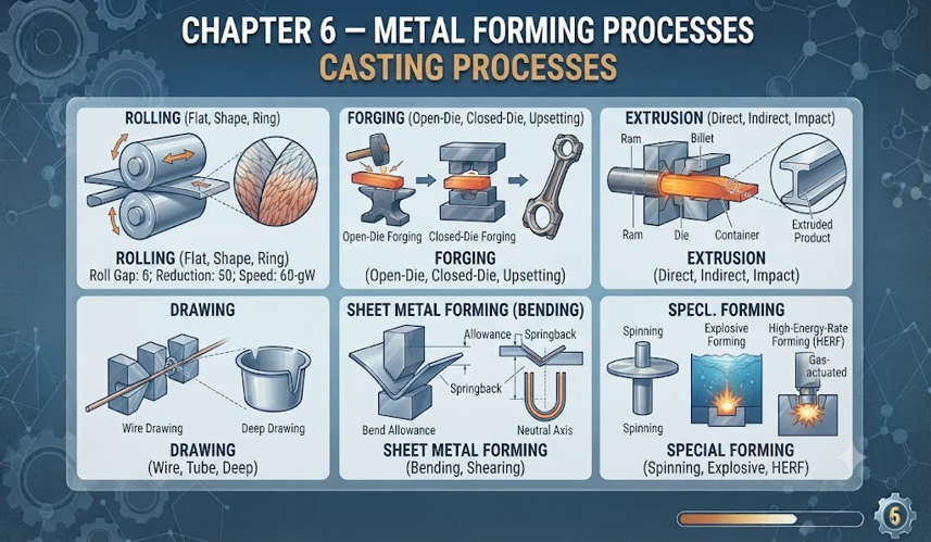
6.1 Introduction
Metal forming is a manufacturing process in which a metal workpiece is plastically deformed into the required shape by applying an external force.
Unlike machining, metal forming generally does not remove material in the form of chips.
Metal forming is widely used in:
Automobile components
Railway components
Aircraft structures
Machine parts
Pipes and tubes
Sheets and plates
Shafts
Gears
Connecting rods
Bolts and fasteners
6.2 Definition of Metal Forming
Metal forming is a manufacturing process in which the shape of a metal is changed permanently by plastic deformation under the action of externally applied forces.
Key Point
Metal forming → Plastic deformation → Required shape
6.3 Principle of Metal Forming
The basic principle is based on the plasticity of metals.
When a sufficiently large force is applied to a metal:
Elastic deformation occurs initially.
The applied stress reaches the yield strength.
Plastic deformation begins.
After removal of the load, the material retains its newly formed shape.
Therefore:
Elastic deformation → Yielding → Plastic deformation → Permanent shape
6.4 Classification of Metal Forming
Metal forming processes can broadly be classified into:
A. Bulk Deformation Processes
These involve relatively large changes in cross-section.
Important processes:
Rolling
Forging
Extrusion
Drawing
B. Sheet Metal Forming Processes
These are generally performed on sheet or strip materials.
Important processes:
Bending
Deep drawing
Blanking
Punching
Bending
Shearing
Embossing
Coining
6.5 Hot Working
Hot working is metal deformation carried out at a temperature sufficiently high that significant recrystallization occurs during deformation.
Examples:
Hot rolling
Hot forging
Hot extrusion
Advantages
Lower forming force
Large deformation possible
Improved workability
Grain refinement can occur
Internal defects may be reduced or closed under suitable conditions
Disadvantages
Oxidation/scaling
Poorer surface finish
Less dimensional accuracy than many cold-working operations
Heating equipment required
6.6 Cold Working
Cold working is plastic deformation performed below the recrystallization temperature, commonly near room temperature.
Examples:
Cold rolling
Wire drawing
Cold extrusion
Cold forging
Advantages
Better surface finish
Better dimensional accuracy
Increased strength and hardness due to strain hardening
No heating scale from hot working
Disadvantages
Higher forming force
Lower ductility
Residual stresses may develop
Greater tool wear can occur
6.7 Warm Working
Warm working is carried out at a temperature between typical cold-working and hot-working conditions.
It can provide a compromise between:
Lower forming force than cold working
Better surface and dimensional control than many hot-working operations
6.8 Recrystallization
Recrystallization is the formation of new, relatively strain-free grains in a plastically deformed metal during appropriate heat treatment.
The recrystallization temperature is important in distinguishing hot and cold working.
Remember
Above suitable recrystallization conditions → Hot working
Below recrystallization temperature → Cold working
6.9 Strain Hardening
Strain hardening, also called work hardening, is the increase in strength and hardness of a metal due to plastic deformation.
It is particularly important in cold working.
Effect of Cold Working
Generally:
Strength ↑
Hardness ↑
Ductility ↓
6.10 Rolling
Rolling is a metal-forming process in which metal is passed between rotating rolls to reduce thickness or change its cross-sectional shape.
Basic principle
Metal → Rotating rolls → Plastic deformation → Reduced thickness/changed shape
6.11 Products of Rolling
Rolling can produce:
Sheets
Plates
Strips
Bars
Rails
Structural sections
Rods
6.12 Types of Rolling Mills
Important rolling-mill arrangements include:
Two-high rolling mill
Three-high rolling mill
Four-high rolling mill
Cluster rolling mill
Tandem rolling mill
6.13 Two-High Rolling Mill
A two-high rolling mill has:
Two rolls
The rolls may rotate in opposite directions at the point of contact with the workpiece.
6.14 Three-High Rolling Mill
A three-high mill consists of:
Three rolls arranged vertically.
The workpiece can pass alternately between the upper and middle rolls and between the middle and lower rolls.
6.15 Four-High Rolling Mill
A four-high rolling mill consists of:
Two small work rolls
Two larger backup rolls
Main purpose of backup rolls
They support the smaller work rolls and reduce bending.
6.16 Cluster Rolling Mill
A cluster mill uses multiple backup rolls to support relatively small work rolls.
It is useful for rolling thin material.
6.17 Tandem Rolling Mill
A tandem rolling mill contains several rolling stands arranged in succession.
The strip passes continuously through multiple stands.
Advantage
High production rate.
6.18 Roll Bite
The roll bite is the region where the workpiece is in contact with the rolls.
For rolling to occur, friction between the rolls and workpiece must be sufficient to draw the material into the roll gap.
6.19 Neutral Point
The neutral point is the point along the arc of contact where the velocity of the strip equals the peripheral velocity of the roll.
6.20 Forward Slip
In rolling, the exit velocity of the strip is generally greater than the peripheral velocity of the roll.
This difference is associated with forward slip.
6.21 Forging
Forging is a metal-forming process in which a workpiece is plastically deformed under compressive forces.
Forces may be applied using:
Hammer
Press
Die
Forging is widely used for producing:
Crankshafts
Connecting rods
Spanners
Axles
Shafts
Bolts
Aircraft components
6.22 Advantages of Forging
Important advantages include:
High strength
Good toughness
Improved grain flow
Reduced internal defects under suitable processing
Excellent mechanical properties for many applications
6.23 Open-Die Forging
In open-die forging, the workpiece is compressed between dies that do not completely enclose it.
It is commonly used for:
Large components
Low-to-medium production
Large shafts
Heavy forgings
6.24 Closed-Die Forging
In closed-die forging, the workpiece is deformed within impressions in the dies.
It is suitable for:
Complex shapes
High production
Better dimensional consistency
Excess material may form flash at the die parting line.
6.25 Flash
Flash is excess metal squeezed out between the die halves during closed-die forging.
The flash is generally removed after forging.
6.26 Drop Forging
Drop forging uses repeated blows from a hammer to deform the workpiece in dies.
The energy of the falling hammer produces the deformation.
6.27 Press Forging
In press forging, deformation is produced primarily by continuous squeezing pressure rather than repeated impact blows.
Comparison
Hammer forging → Impact
Press forging → Continuous pressure
6.28 Extrusion
Extrusion is a metal-forming process in which a billet is forced through a die opening to produce a long product of constant cross-section.
Examples:
Rods
Tubes
Channels
Aluminium sections
Window frames
6.29 Direct Extrusion
In direct extrusion, the billet and ram move in the same direction relative to the die opening.
The ram pushes the billet through the die.
6.30 Indirect Extrusion
In indirect extrusion, the die moves toward or into the billet, and the extruded material flows opposite to the direction of ram movement.
Important
Direct extrusion → Billet flow generally same direction as ram movement
Indirect extrusion → Metal flow opposite to ram movement
6.31 Extrusion Ratio
The extrusion ratio is generally defined as:
Where:
= initial cross-sectional area
= final extruded cross-sectional area
A larger extrusion ratio indicates a greater reduction in cross-sectional area.
6.32 Drawing
Drawing is a metal-forming process in which a wire, rod or tube is pulled through a die to reduce its cross-sectional area and/or change its shape.
Important
Extrusion → Material is pushed through die
Drawing → Material is pulled through die
6.33 Wire Drawing
Wire drawing is commonly used to produce:
Electrical wires
Fine wires
Cables
Springs
Small-diameter rods
6.34 Tube Drawing
Tube drawing is used to reduce the diameter or wall dimensions of tubes.
A mandrel may be used when control of internal dimensions is required.
6.35 Sheet Metal Working
Sheet metal processes transform thin metal sheets into useful components.
Common operations include:
Shearing
Blanking
Punching
Bending
Deep drawing
Embossing
Coining
6.36 Shearing
Shearing is a cutting operation in which a sheet is separated by applying shear forces.
It is performed using tools such as:
Shears
Punch and die
6.37 Blanking
In blanking, the portion cut out from the sheet is the desired product.
Golden Rule
Blanking → Blank is the product
6.38 Punching
In punching, the hole produced in the sheet is the desired feature, while the removed slug is generally scrap.
Golden Rule
Punching → Hole is the desired feature
6.39 Bending
Bending changes the shape of a sheet or strip by applying force without intentionally removing material.
Examples:
V-bending
U-bending
Angle bending
6.40 Springback
Springback is the elastic recovery of a sheet after the bending load is removed.
Because of springback, the final angle may differ from the angle imposed by the tooling.
Reduction of Springback
It can be controlled by:
Over-bending
Coining
Appropriate tooling
Process optimization
6.41 Deep Drawing
Deep drawing is a sheet-metal forming process in which a flat blank is drawn into a die to produce a cup-like or hollow component.
Examples:
Cups
Cans
Kitchen utensils
Automotive components
6.42 Blank Holder
A blank holder is used in deep drawing to control the movement of the sheet and help prevent wrinkling.
6.43 Punch and Die
In sheet-metal operations:
Punch → Moves into/through the sheet
Die → Supports and provides the required opening
The clearance between punch and die is important for cutting quality and tool life.
6.44 Embossing
Embossing produces raised or recessed designs on sheet metal.
It is commonly used for:
Identification marks
Decorative patterns
Stiffening features
6.45 Coining
Coining is a severe sheet-metal forming operation in which the material is subjected to high compressive pressure between dies.
It can produce:
Fine details
Accurate impressions
Raised or recessed features
6.46 Advantages of Metal Forming
Major advantages:
High production rate
Good material utilization
Improved mechanical properties in many processes
Good surface finish in cold working
Reduced machining requirements
Suitable for mass production
6.47 Limitations
Limitations include:
High initial tooling cost
High forming forces
Springback in sheet-metal forming
Work hardening
Residual stresses
Defects such as laps, cracks and wrinkles
6.48 Common Forming Defects
Important defects include:
Cracks
Laps
Wrinkles
Surface defects
Internal defects
Alligatoring
Excessive springback
6.49 Quick Revision Table
Process Main Principle
Rolling Metal passes between rolls
Forging Compressive deformation
Extrusion Pushing metal through die
Drawing Pulling metal through die
Blanking Cut-out piece is product
Punching Hole is desired feature
Bending Change in sheet angle/shape
Deep drawing Sheet converted into cup/hollow form
Embossing Raised/recessed design
Coining High-pressure impression
Hot working Above suitable recrystallization conditions
Cold working Below recrystallization temperature
Warm working Intermediate temperature range
Springback Elastic recovery
Strain hardening Strength increase due to plastic deformation
Q1. Metal forming is primarily based on:
A. Elastic deformation
B. Plastic deformation
C. Brittle fracture
D. Melting
Answer: B. Plastic deformation
Explanation: Metal forming permanently changes the shape of a material through plastic deformation.
Q2. Which of the following is a bulk metal-forming process?
A. Rolling
B. Painting
C. Welding
D. Grinding
Answer: A. Rolling
Explanation: Rolling is one of the major bulk deformation processes.
Q3. Which process uses rotating rolls to reduce the thickness of metal?
A. Forging
B. Rolling
C. Drawing
D. Casting
Answer: B. Rolling
Explanation: Rolling passes the workpiece through the gap between rotating rolls.
Q4. Forging primarily involves:
A. Tensile forces
B. Compressive forces
C. Electrical forces
D. Thermal radiation only
Answer: B. Compressive forces
Explanation: Forging plastically deforms the workpiece mainly through compressive loading.
Q5. In extrusion, the billet is:
A. Pulled through the die
B. Pushed through the die
C. Melted completely
D. Rolled into a sheet
Answer: B. Pushed through the die
Explanation: A ram applies compressive force to force the billet through the die opening.
Q6. In drawing, the workpiece is:
A. Pushed through the die
B. Pulled through the die
C. Melted
D. Cast
Answer: B. Pulled through the die
Explanation: Drawing reduces the cross-section by pulling the material through a die.
Q7. Which process generally increases hardness due to strain hardening?
A. Cold working
B. Annealing
C. Casting only
D. Melting
Answer: A. Cold working
Explanation: Plastic deformation at low temperature increases dislocation density, generally increasing strength and hardness.
Q8. One common disadvantage of cold working is:
A. Increased ductility
B. Work hardening
C. Complete elimination of residual stress
D. Loss of all strength
Answer: B. Work hardening
Explanation: Cold deformation increases strength and hardness but reduces ductility.
Q9. Which process is generally performed at a temperature where recrystallization can occur during deformation?
A. Hot working
B. Cold working
C. Room-temperature machining
D. Grinding
Answer: A. Hot working
Explanation: Hot working occurs at sufficiently elevated temperatures to permit significant recrystallization during deformation.
Q10. Which of the following is a sheet-metal operation?
A. Deep drawing
B. Blast furnace melting
C. Sand moulding
D. Arc welding
Answer: A. Deep drawing
Explanation: Deep drawing forms sheet metal into cup-like or hollow shapes.
Q11. In blanking:
A. The hole is the product
B. The blank is the product
C. Both are always scrap
D. No material is removed
Answer: B. The blank is the product
Explanation: The cut-out portion of the sheet is the desired component in blanking.
Q12. In punching:
A. The hole is the desired feature
B. The slug is always the final product
C. No cutting occurs
D. The sheet is melted
Answer: A. The hole is the desired feature
Explanation: Punching produces a hole in the sheet; the removed slug is generally scrap.
Q13. Springback in sheet metal is caused by:
A. Elastic recovery
B. Melting
C. Plastic flow only
D. Oxidation
Answer: A. Elastic recovery
Explanation: After the forming load is removed, the elastically deformed material partially returns toward its original shape.
Q14. Which operation produces a cup-like component from a flat sheet?
A. Deep drawing
B. Rolling
C. Wire drawing
D. Forging
Answer: A. Deep drawing
Explanation: Deep drawing transforms a flat blank into a hollow component.
Q15. A four-high rolling mill uses:
A. Four work rolls
B. Two work rolls and two backup rolls
C. One work roll and three dies
D. Four dies
Answer: B. Two work rolls and two backup rolls
Explanation: The smaller work rolls are supported by larger backup rolls.
Q16. A tandem rolling mill consists of:
A. Several rolling stands in succession
B. One die only
C. One hammer only
D. A furnace and a mould
Answer: A. Several rolling stands in succession
Explanation: Multiple stands permit successive reductions and high production rates.
Q17. Excess metal squeezed out between closed forging dies is called:
A. Flash
B. Burr only
C. Slag
D. Riser
Answer: A. Flash
Explanation: Flash forms at the die parting line during closed-die forging and is subsequently trimmed.
Q18. Open-die forging is especially suitable for:
A. Large components
B. Only tiny electronic parts
C. Thin plastic films
D. Glass bottles
Answer: A. Large components
Explanation: Open-die forging is commonly used for large shafts, rings and other heavy components.
Q19. The extrusion ratio is generally:
A.
B.
C.
D.
Answer: B.
Explanation:
where is the initial billet area and is the final extruded area.
Q20. In indirect extrusion, metal flow is generally:
A. In the same direction as ram movement
B. Opposite to ram movement
C. Perpendicular to the die
D. Circular only
Answer: B. Opposite to ram movement
Explanation: In indirect extrusion, the die moves into the billet and material flows through the die in the opposite direction to the ram.
Q21. The main purpose of rolling is to:
A. Increase the thickness of a plate
B. Reduce thickness or change cross-section
C. Join two metals
D. Remove chips
Answer: B. Reduce thickness or change cross-section
Explanation: Rolling plastically deforms metal between rotating rolls to reduce thickness or produce a required section.
Q22. In rolling, the workpiece is subjected mainly to:
A. Tensile stress
B. Compressive stress
C. Torsional stress only
D. Bending stress only
Answer: B. Compressive stress
Explanation: The rolls apply compressive forces to reduce the thickness of the workpiece.
Q23. Which product can commonly be manufactured by rolling?
A. Sheet
B. Sand mould
C. Welding electrode only
D. Cutting fluid
Answer: A. Sheet
Explanation: Sheets, plates, strips, rails and structural sections are common rolling products.
Q24. The distance between the surfaces of two rolls at the point of minimum separation is called:
A. Roll gap
B. Draft angle
C. Die clearance
D. Pitch
Answer: A. Roll gap
Explanation: Roll gap is the minimum separation between the two rolls through which the material passes.
Q25. Draft in rolling refers to:
A. Increase in thickness
B. Reduction in thickness
C. Increase in width only
D. Reduction in length only
Answer: B. Reduction in thickness
Explanation:
where is the initial thickness and is the final thickness.
Q26. If the initial thickness is 20 mm and final thickness is 15 mm, the draft is:
A. 3 mm
B. 5 mm
C. 15 mm
D. 35 mm
Answer: B. 5 mm
Explanation:
Q27. The percentage reduction in thickness is calculated by:
A.
B.
C.
D.
Answer: B.
Explanation: Percentage reduction represents the decrease in thickness relative to the initial thickness.
Q28. The roll bite is the region where:
A. Metal is heated
B. Metal contacts the rolls
C. Metal is melted
D. Metal is welded
Answer: B. Metal contacts the rolls
Explanation: The arc or region of contact between the workpiece and rolls is associated with the roll bite.
Q29. Friction between the rolls and workpiece is necessary primarily to:
A. Prevent deformation
B. Draw the workpiece into the rolls
C. Melt the workpiece
D. Increase electrical resistance
Answer: B. Draw the workpiece into the rolls
Explanation: Adequate friction enables the rolls to grip and pull the workpiece into the roll gap.
Q30. Excessive friction in rolling can lead to:
A. Reduced roll wear
B. Increased power requirement and defects
C. Zero deformation
D. Elimination of all stresses
Answer: B. Increased power requirement and defects
Explanation: Although friction is required for biting, excessive friction increases power consumption and may promote undesirable deformation.
Q31. A two-high rolling mill consists of:
A. Two rolls
B. Three rolls
C. Four rolls
D. Six rolls
Answer: A. Two rolls
Explanation: The simplest rolling mill arrangement has two rolls.
Q32. In a three-high rolling mill, the rolls are generally arranged:
A. Horizontally in one plane
B. Vertically one above another
C. In a triangular pattern
D. Randomly
Answer: B. Vertically one above another
Explanation: Three-high mills use three rolls positioned one above another.
Q33. The major advantage of a three-high rolling mill is:
A. Reversal of workpiece movement without reversing roll rotation
B. No need for friction
C. No deformation
D. Elimination of all roll wear
Answer: A. Reversal of workpiece movement without reversing roll rotation
Explanation: The workpiece can pass alternately through the upper and lower roll gaps while the rolls continue rotating in their respective directions.
Q34. In a four-high rolling mill, backup rolls are used mainly to:
A. Heat the metal
B. Support work rolls
C. Cut the metal
D. Lubricate the workpiece
Answer: B. Support work rolls
Explanation: Backup rolls reduce bending of the smaller work rolls.
Q35. A cluster rolling mill is particularly suitable for:
A. Very thin sheets
B. Sand casting
C. Forging dies only
D. Welding rods only
Answer: A. Very thin sheets
Explanation: Multiple backup rolls permit the use of small work rolls and help produce thin material.
Q36. A tandem rolling mill is used mainly for:
A. Low-speed single-piece production
B. High production rate
C. Hand forging
D. Sand mould preparation
Answer: B. High production rate
Explanation: Multiple stands arranged sequentially permit continuous high-speed rolling.
Q37. In rolling, the neutral point is where:
A. Metal melts
B. Strip velocity equals roll surface velocity
C. Thickness becomes zero
D. Friction becomes zero
Answer: B. Strip velocity equals roll surface velocity
Explanation: The neutral point separates regions of backward and forward slip.
Q38. Forward slip occurs because:
A. Exit strip velocity is greater than roll peripheral velocity
B. Exit strip velocity is zero
C. Roll velocity is always greater than strip velocity
D. The strip melts
Answer: A. Exit strip velocity is greater than roll peripheral velocity
Explanation: The strip accelerates as it moves through the roll bite, resulting in forward slip at exit.
Q39. Roll flattening is caused mainly by:
A. High rolling force
B. Low temperature of air
C. Pattern draft
D. Core expansion
Answer: A. High rolling force
Explanation: Large rolling forces elastically deform the rolls, affecting the effective roll gap.
Q40. Which defect is associated with excessive non-uniform deformation during rolling?
A. Wavy edges
B. Blowhole
C. Cold shut
D. Hot tear
Answer: A. Wavy edges
Explanation: Unequal elongation across the strip width can produce wavy edges.
MCQ 41–60: Forging
Q41. Forging is primarily a:
A. Casting process
B. Metal-forming process
C. Machining process
D. Welding process
Answer: B. Metal-forming process
Explanation: Forging changes the shape of a workpiece through plastic deformation under compressive loading.
Q42. The major force in forging is:
A. Compression
B. Tension
C. Pure torsion
D. Electrical force
Answer: A. Compression
Explanation: Forging dies apply compressive forces to deform the workpiece.
Q43. Open-die forging is generally preferred for:
A. Very large components
B. Tiny electronic components
C. Plastic sheets
D. Glass products
Answer: A. Very large components
Explanation: Open dies can accommodate large workpieces and are widely used for heavy forgings.
Q44. Closed-die forging is particularly suitable for:
A. Complex shapes and high production
B. Only rough large blocks
C. Sand moulds
D. Thin wires only
Answer: A. Complex shapes and high production
Explanation: Die impressions provide controlled shaping and repeatability.
Q45. Flash in closed-die forging is:
A. Molten slag
B. Excess metal squeezed out at the die parting line
C. Lubricant
D. A crack in the forging
Answer: B. Excess metal squeezed out at the die parting line
Explanation: Excess material flows into the flash region between the die halves.
Q46. Flash is generally removed by:
A. Trimming
B. Rolling
C. Casting
D. Annealing only
Answer: A. Trimming
Explanation: A trimming operation removes unwanted flash from the forged component.
Q47. Drop forging uses:
A. Repeated hammer blows
B. Continuous rolling
C. Wire drawing
D. A rotating mould
Answer: A. Repeated hammer blows
Explanation: A hammer delivers impact energy to deform the workpiece within the dies.
Q48. Press forging differs from drop forging because press forging uses mainly:
A. Continuous squeezing action
B. No force
C. Melting
D. Tensile fracture
Answer: A. Continuous squeezing action
Explanation: A forging press applies force progressively rather than mainly through repeated impact blows.
Q49. Which is a major advantage of forged components?
A. Improved grain flow
B. Guaranteed zero machining
C. No tooling required
D. Very low strength
Answer: A. Improved grain flow
Explanation: Proper forging can produce favorable grain flow and excellent mechanical properties.
Q50. Forging is widely used for manufacturing:
A. Connecting rods
B. Glass bottles
C. Sand moulds
D. Plastic films
Answer: A. Connecting rods
Explanation: Connecting rods are commonly produced by forging because of the required strength and toughness.
Q51. A forging defect in which the material folds over itself is called:
A. Lap
B. Blowhole
C. Misrun
D. Porosity
Answer: A. Lap
Explanation: A lap is a surface defect caused by folding of metal during deformation.
Q52. Proper die design is important mainly to:
A. Ensure controlled metal flow
B. Eliminate all friction
C. Melt the workpiece
D. Produce sand
Answer: A. Ensure controlled metal flow
Explanation: Proper die geometry helps material flow correctly and reduces forging defects.
Q53. In impression-die forging, the workpiece is deformed:
A. Within die impressions
B. Between rolling rolls
C. Through a wire-drawing die
D. Inside a sand mould
Answer: A. Within die impressions
Explanation: Die cavities define the desired forging geometry.
Q54. The grain flow produced by forging can improve:
A. Mechanical performance
B. Electrical insulation only
C. Casting permeability
D. Melting temperature only
Answer: A. Mechanical performance
Explanation: Favorable grain flow can improve fatigue strength, toughness and directional mechanical properties.
Q55. Hot forging generally requires:
A. Lower deformation force than cold forging
B. No deformation force
C. Only tensile force
D. No dies
Answer: A. Lower deformation force than cold forging
Explanation: Elevated temperature lowers the flow stress of the material.
Q56. Cold forging generally provides:
A. Good dimensional accuracy and surface finish
B. Heavy oxidation scale
C. Very low strength
D. No work hardening
Answer: A. Good dimensional accuracy and surface finish
Explanation: Cold forging can produce accurate parts and also increases strength through work hardening.
Q57. Which process is commonly used to manufacture bolts in large quantities?
A. Cold heading/cold forging
B. Sand casting only
C. Centrifugal casting
D. Investment casting only
Answer: A. Cold heading/cold forging
Explanation: Cold heading is widely used for high-volume production of fasteners.
Q58. Upsetting in forging generally:
A. Increases cross-sectional area and reduces length
B. Reduces diameter and increases length
C. Produces a hole
D. Cuts the material
Answer: A. Increases cross-sectional area and reduces length
Explanation: In upsetting, the workpiece is compressed along its length.
Q59. Drawing out in forging generally:
A. Increases length and reduces cross-section
B. Decreases length
C. Produces a hole
D. Produces sheet by rolling
Answer: A. Increases length and reduces cross-section
Explanation: Drawing out elongates the workpiece while reducing its cross-sectional dimensions.
Q60. A forging hammer applies:
A. Impact load
B. Pure hydrostatic pressure only
C. Tensile load only
D. Electrical current
Answer: A. Impact load
Explanation: Hammers deform the workpiece using high-energy impact blows.
MCQ 61–80: Extrusion & Drawing
Q61. Extrusion produces:
A. Long products of constant cross-section
B. Only spherical products
C. Only flat sheets
D. Sand moulds
Answer: A. Long products of constant cross-section
Explanation: Material is forced through a die to obtain the required continuous cross-sectional shape.
Q62. In direct extrusion, metal flow is generally:
A. In the direction of ram movement
B. Opposite to ram movement
C. Perpendicular to ram movement
D. Circular
Answer: A. In the direction of ram movement
Explanation: The ram pushes the billet toward and through the die.
Q63. The major advantage of indirect extrusion is:
A. Lower friction between billet and container
B. No deformation
C. No die required
D. No pressure required
Answer: A. Lower friction between billet and container
Explanation: In indirect extrusion, there is less relative movement between the billet and container wall.
Q64. Extrusion is especially suitable for producing:
A. Complex cross-sections
B. Only cast iron blocks
C. Sand cores
D. Weld beads
Answer: A. Complex cross-sections
Explanation: Extrusion can produce intricate and constant cross-sectional profiles.
Q65. Aluminium is widely extruded because of its:
A. Good extrudability
B. Extremely high brittleness
C. Very low plasticity
D. Inability to deform
Answer: A. Good extrudability
Explanation: Aluminium alloys are widely used for extruded sections because many grades have good workability.
Q66. In extrusion, the die determines:
A. Final cross-sectional shape
B. Furnace fuel
C. Metal colour
D. Workpiece temperature only
Answer: A. Final cross-sectional shape
Explanation: The opening in the extrusion die defines the cross-sectional profile of the product.
Q67. The extrusion ratio is the ratio of:
A. Final area to initial area
B. Initial area to final area
C. Initial length to final length
D. Final length to initial length
Answer: B. Initial area to final area
Explanation:
Q68. In wire drawing, the material is:
A. Pulled through a die
B. Pushed through a die
C. Cast into a mould
D. Rolled between four rolls
Answer: A. Pulled through a die
Explanation: Tensile force pulls the wire through the die, reducing its cross-section.
Q69. Wire drawing is commonly used to manufacture:
A. Fine wires
B. Large castings
C. Engine blocks
D. Sand moulds
Answer: A. Fine wires
Explanation: Drawing is an important process for reducing wire diameter.
Q70. The material property most important for successful wire drawing is:
A. Ductility
B. Brittleness
C. Porosity
D. Very low strength
Answer: A. Ductility
Explanation: The material must withstand substantial plastic deformation without cracking.
Q71. A drawing die is used to:
A. Reduce cross-sectional area
B. Increase melting temperature
C. Produce a mould cavity
D. Join two wires
Answer: A. Reduce cross-sectional area
Explanation: The die opening is smaller than the incoming material cross-section.
Q72. Lubrication in drawing is used mainly to:
A. Reduce friction and die wear
B. Increase friction
C. Melt the material
D. Increase oxidation
Answer: A. Reduce friction and die wear
Explanation: Proper lubrication lowers frictional resistance and improves tool life and surface quality.
Q73. Tube drawing may use a mandrel to control:
A. Internal dimensions
B. Furnace temperature
C. External colour
D. Sheet thickness only
Answer: A. Internal dimensions
Explanation: A mandrel supports and controls the internal surface during tube drawing.
Q74. In extrusion, the material is subjected mainly to:
A. Compressive stress
B. Tensile stress only
C. Pure bending
D. Impact only
Answer: A. Compressive stress
Explanation: The ram applies compressive force to push the billet through the die.
Q75. In drawing, the material is subjected significantly to:
A. Tensile stress
B. Pure compression only
C. Bending only
D. Impact only
Answer: A. Tensile stress
Explanation: The drawing force pulls the workpiece through the die.
Q76. Which process can produce an aluminium window-frame profile?
A. Extrusion
B. Punching only
C. Deep drawing only
D. Open-die forging only
Answer: A. Extrusion
Explanation: Extrusion is widely used for long aluminium profiles with complex constant cross-sections.
Q77. In indirect extrusion, friction between billet and container is generally:
A. Lower than in direct extrusion
B. Higher than in direct extrusion
C. Always zero
D. Unrelated to the process
Answer: A. Lower than in direct extrusion
Explanation: The billet does not slide relative to the container in the same manner as in direct extrusion.
Q78. Which process is more appropriate for reducing the diameter of a wire?
A. Wire drawing
B. Forging
C. Casting
D. Deep drawing
Answer: A. Wire drawing
Explanation: Wire drawing is specifically designed for producing smaller wire diameters.
Q79. Which process is generally associated with pushing a billet through a die?
A. Extrusion
B. Drawing
C. Bending
D. Shearing
Answer: A. Extrusion
Explanation: Extrusion uses compressive force to push material through the die.
Q80. Which process is generally associated with pulling a workpiece through a die?
A. Drawing
B. Extrusion
C. Rolling
D. Forging
Answer: A. Drawing
Explanation: Drawing uses tensile pulling force to pass the material through a die.
MCQ 81–100: Sheet Metal Processes
Q81. Sheet metal working is generally performed on:
A. Thin sheets and strips
B. Molten metal only
C. Sand
D. Wooden blocks
Answer: A. Thin sheets and strips
Explanation: Sheet-metal processes shape and cut relatively thin metal stock.
Q82. Which operation separates sheet metal by shear?
A. Shearing
B. Forging
C. Extrusion
D. Rolling only
Answer: A. Shearing
Explanation: Shearing separates sheet material through localized shear deformation.
Q83. In blanking, the cut-out portion is:
A. The desired component
B. Always scrap
C. The punch
D. The die
Answer: A. The desired component
Explanation: The blank is the required product in blanking.
Q84. In punching, the removed portion is generally:
A. Scrap
B. The final sheet
C. The die
D. The punch
Answer: A. Scrap
Explanation: The hole is the desired feature, while the removed slug is generally discarded.
Q85. The tool that enters the sheet during punching is:
A. Punch
B. Riser
C. Core
D. Runner
Answer: A. Punch
Explanation: The punch moves relative to the die and cuts the sheet.
Q86. Clearance in a punching operation is provided between:
A. Punch and die
B. Riser and runner
C. Core and mould box
D. Hammer and anvil only
Answer: A. Punch and die
Explanation: Proper punch-die clearance is essential for good cutting quality and tool life.
Q87. Excessive clearance in blanking may produce:
A. Poor edge quality
B. Perfect edge quality always
C. No cutting
D. No deformation
Answer: A. Poor edge quality
Explanation: Incorrect clearance can increase burr formation and reduce cut quality.
Q88. Bending is primarily used to:
A. Change the shape/angle of sheet metal
B. Remove large amounts of material
C. Melt sheet metal
D. Cast a component
Answer: A. Change the shape/angle of sheet metal
Explanation: Bending plastically deforms the sheet around an axis.
Q89. Springback is particularly important in:
A. Sheet-metal bending
B. Sand casting
C. Cupola operation
D. Welding electrode coating
Answer: A. Sheet-metal bending
Explanation: Elastic recovery after bending changes the final angle and shape.
Q90. One method used to compensate for springback is:
A. Over-bending
B. Removing all tooling
C. Reducing all forces to zero
D. Increasing sheet thickness indefinitely
Answer: A. Over-bending
Explanation: The material can be bent slightly beyond the required angle so that elastic recovery brings it closer to the desired final angle.
Q91. Deep drawing uses:
A. Punch and die
B. Only rolling rolls
C. Only a hammer
D. A cupola
Answer: A. Punch and die
Explanation: The punch pushes the sheet blank into the die cavity to form the desired hollow shape.
Q92. A blank holder in deep drawing is used mainly to:
A. Control material flow and reduce wrinkling
B. Melt the blank
C. Increase casting shrinkage
D. Cut the blank completely
Answer: A. Control material flow and reduce wrinkling
Explanation: The blank holder controls the flange region during drawing.
Q93. Wrinkling in deep drawing is associated mainly with:
A. Compressive stresses in the flange
B. Tensile stress only
C. Melting
D. Welding
Answer: A. Compressive stresses in the flange
Explanation: Compressive circumferential stresses can cause the flange to buckle and form wrinkles.
Q94. Excessive tensile stress in deep drawing can cause:
A. Tearing
B. Wrinkling only
C. Embossing
D. Coining
Answer: A. Tearing
Explanation: Excessive drawing force can exceed the material’s forming capability and cause tearing.
Q95. Embossing is used to produce:
A. Raised or recessed patterns
B. Deep holes only
C. Cast cavities
D. Forging flash
Answer: A. Raised or recessed patterns
Explanation: Embossing forms localized raised or recessed features in sheet metal.
Q96. Coining involves:
A. High compressive pressure
B. Only tensile loading
C. Melting
D. Sand moulding
Answer: A. High compressive pressure
Explanation: Coining uses high pressure between dies to produce detailed impressions.
Q97. Which operation is used to produce a hollow cylindrical component from sheet metal?
A. Deep drawing
B. Rolling
C. Wire drawing
D. Open-die forging
Answer: A. Deep drawing
Explanation: Deep drawing converts a flat blank into a hollow shape.
Q98. Which of the following is NOT normally classified as a sheet-metal cutting operation?
A. Punching
B. Blanking
C. Shearing
D. Deep drawing
Answer: D. Deep drawing
Explanation: Deep drawing is a forming operation rather than a cutting operation.
Q99. Which operation produces the required blank by cutting it from a sheet?
A. Blanking
B. Drawing
C. Forging
D. Extrusion
Answer: A. Blanking
Explanation: The separated blank becomes the desired product.
Q100. Which operation produces a hole as the desired result?
A. Punching
B. Blanking
C. Rolling
D. Extrusion
Answer: A. Punching
Explanation: In punching, the hole is the required feature and the removed slug is generally scrap.
CHAPTER 6 — EXAM REVISION CAPSULE
Remember these pairs:
Rolling → Rolls
Forging → Compression
Extrusion → Push through die
Drawing → Pull through die
Blanking → Blank is product
Punching → Hole is product
Deep Drawing → Cup/hollow component
Bending → Sheet angle changes
Embossing → Raised/recessed design
Coining → High-pressure impression
Hot Working → Recrystallization during deformation
Cold Working → Work hardening
Springback → Elastic recovery
Important Numerical Formulae
Draft in Rolling
Percentage Reduction
Extrusion Ratio
WHERE:
= Initial cross-sectional area
= Final cross-sectional area
CHAPTER 7 — WELDING TECHNOLOGY
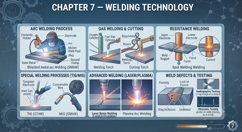
7.1 Introduction
Welding is one of the most important permanent joining processes used in manufacturing and workshop technology.
It is extensively used in:
Automobile manufacturing
Railway equipment
Bridges
Pressure vessels
Pipelines
Shipbuilding
Structural fabrication
Machine frames
Boilers
Storage tanks
Aerospace components
Unlike temporary fastening methods such as nuts and bolts, welding generally produces a permanent joint.
7.2 Definition of Welding
Welding is a permanent joining process in which two or mo
re materials are joined by applying heat, pressure, or a combination of heat and pressure, with or without the use of filler material.
Key Concept
Welding → Permanent joining → Heat/Pressure → Joint
7.3 Objectives of Welding
The main objectives are:
To permanently join two or more components.
To produce a strong joint.
To fabricate complex structures.
To repair damaged components.
To manufacture large structures economically.
To join similar or, with suitable processes, dissimilar materials.
7.4 Welding vs Brazing vs Soldering
These three processes are frequently asked in competitive examinations.
Process Basic Principle Filler Metal
Welding Base metals are joined by heat/pressure May or may not be used
Brazing Filler metal melts above 450°C Used
Soldering Filler metal melts below 450°C Used
Important
Brazing: Filler metal melting temperature is above 450°C but below the melting temperature of the base metals.
Soldering: Filler metal melting temperature is below 450°C.
7.5 Classification of Welding Processes
Welding processes can broadly be classified as:
A. Fusion Welding
The base metal is melted during joining.
Examples:
Gas welding
Arc welding
Thermit welding
Laser beam welding
Electron beam welding
B. Solid-State Welding
The base metals are joined without melting the base material.
Examples:
Forge welding
Friction welding
Diffusion welding
Ultrasonic welding
Explosive welding
7.6 Arc Welding
Arc welding uses an electric arc to generate heat for melting the workpiece and, where applicable, the electrode/filler.
The temperature of an electric arc is extremely high and is sufficient to melt many engineering metals.
7.7 Electric Arc
An electric arc is established between:
Electrode and workpiece, or
Two electrodes
The electrical energy is converted into heat energy.
Basic Principle
Electrical energy → Arc → Heat → Melting → Weld joint
7.8 Shielded Metal Arc Welding (SMAW)
SMAW is commonly known as:
Manual Metal Arc Welding (MMA/MMAW)
It uses a flux-coated consumable electrode.
Main Features
Electrode is consumable.
Electrode coating provides shielding.
Slag is formed.
Suitable for many fabrication applications.
Relatively portable.
7.9 Electrode
An electrode is the component through which electric current is supplied to establish the arc.
Electrodes may be:
Consumable
Non-consumable
Consumable Electrode
The electrode melts and becomes part of the weld metal.
Example:
SMAW electrode
Non-Consumable Electrode
The electrode does not normally become part of the weld.
Example:
TIG tungsten electrode
7.10 Flux
Flux is a material used during welding to assist in removing/preventing oxides and to help protect the molten weld pool.
Functions include:
Preventing atmospheric contamination
Removing oxides
Forming protective slag in relevant processes
Improving weld quality
7.11 Slag
Slag is a non-metallic layer formed over the weld during processes such as shielded metal arc welding.
It protects the molten/solidifying weld metal from atmospheric contamination.
After welding, slag may need to be removed.
7.12 Gas Welding
Gas welding uses heat generated by combustion of a fuel gas with oxygen or another oxidizer.
The most common traditional gas-welding process is:
Oxy-acetylene welding
7.13 Oxy-Acetylene Welding
Oxy-acetylene welding uses:
Oxygen
Acetylene
The gases are mixed and burned at the welding torch.
Applications
Sheet-metal work
Repair work
Pipe work
Cutting
Maintenance operations
7.14 Welding Flame
In oxy-acetylene welding, three important flame types are:
Neutral flame
Carburizing/reducing flame
Oxidizing flame
7.15 Neutral Flame
A neutral flame has approximately balanced oxygen and acetylene proportions.
It has:
Inner cone
Outer envelope
It is widely used for welding many steels and other metals.
Remember
Neutral flame → General-purpose flame
7.16 Carburizing Flame
A carburizing flame is also called a:
Reducing flame
It contains excess acetylene relative to oxygen.
It can introduce carbon-rich/reducing conditions and is useful for selected materials and applications.
7.17 Oxidizing Flame
An oxidizing flame contains excess oxygen.
It is used for specific materials such as certain copper alloys and is generally unsuitable for ordinary welding of steels because excessive oxidation can be harmful.
7.18 TIG Welding
TIG = Tungsten Inert Gas Welding
The modern process designation is:
Gas Tungsten Arc Welding (GTAW)
It uses a non-consumable tungsten electrode and an inert shielding gas.
Common shielding gases include:
Argon
Helium
Important
TIG → Tungsten electrode → Non-consumable
7.19 Advantages of TIG Welding
High-quality welds
Excellent control
Clean welds
No slag from flux-coated electrode
Suitable for thin materials
Suitable for many non-ferrous metals
7.20 MIG Welding
MIG = Metal Inert Gas Welding
It is commonly associated with:
Gas Metal Arc Welding (GMAW)
A continuously fed consumable wire electrode is used.
The shielding gas protects the weld pool from atmospheric contamination.
Important
MIG → Consumable wire electrode
7.21 MIG vs TIG
| Feature | MIG | TIG |
| Electrode | Consumable wire | Non-consumable tungsten |
| Wire feed | Continuous | Separate filler may be used |
| Productivity | Generally high | Generally lower |
| Control | Good | Excellent |
| Typical use | Production | High-quality precision welding |
7.22 Resistance Welding
Resistance welding generates heat due to the electrical resistance of the workpiece.
The heat generated is related to:
Where:
= heat
= current
= electrical resistance
= time
Principle
Electrical resistance → Heat → Pressure → Weld
7.23 Spot Welding
Spot welding is a resistance-welding process in which overlapping sheets are joined at discrete spots.
It is extensively used in:
Automobile bodies
Sheet-metal assemblies
Appliances
7.24 Seam Welding
Seam welding produces a series of overlapping weld nuggets, often forming a continuous or leak-tight seam.
It uses wheel-shaped electrodes.
7.25 Projection Welding
In projection welding, localized projections on one or both components concentrate current and pressure.
It is useful for:
Nuts
Fasteners
Sheet assemblies
7.26 Butt Welding
Butt welding joins components placed approximately end-to-end.
Resistance butt welding is one important form.
7.27 Thermit Welding
Thermit welding uses the heat generated by an exothermic chemical reaction.
A thermit mixture commonly involves:
Aluminium + Metal oxide
The reaction produces intense heat and molten metal.
Application
A famous application is:
Rail joining
7.28 Friction Welding
Friction welding is a solid-state welding process.
Heat is generated by friction between surfaces in relative motion.
After sufficient heating, pressure is applied to form the joint.
Important
Friction welding → Solid-state process
7.29 Ultrasonic Welding
Ultrasonic welding uses:
High-frequency mechanical vibrations
Pressure
It is a solid-state joining process.
It is commonly used for:
Thin sheets
Electrical/electronic components
Certain plastics and metals
7.30 Diffusion Welding
Diffusion welding is a solid-state process in which surfaces are joined under:
Pressure
Elevated temperature
Controlled conditions
Bonding occurs through atomic diffusion across the interface.
7.31 Welding Joints
Common welding joint types include:
- Butt joint
- Lap joint
- T-joint
- Corner joint
- Edge joint
7.32 Butt Joint
In a butt joint, two components are placed approximately:
In the same plane, edge to edge.
7.33 Lap Joint
In a lap joint, two sheets:
Overlap each other.
7.34 T-Joint
A T-joint is formed when one component is positioned approximately perpendicular to another, producing a T-shaped configuration.
7.35 Corner Joint
A corner joint joins two components at a corner.
7.36 Edge Joint
In an edge joint, adjacent edges of two sheets are joined.
7.37 Welding Positions
Common welding positions are:
Flat
Horizontal
Vertical
Overhead
Most difficult among common positions
Overhead welding generally requires greater skill and control.
7.38 Weld Defects
Important welding defects include:
Porosity
Cracks
Undercut
Slag inclusion
Lack of fusion
Lack of penetration
Spatter
Distortion
Burn-through
7.39 Porosity
Porosity consists of cavities or gas pores trapped in the weld metal.
Possible causes include:
Moisture
Contamination
Inadequate shielding
Improper welding parameters
7.40 Undercut
Undercut is a groove formed along the edge/toe of a weld that is not properly filled with weld metal.
Possible causes:
Excessive current
Excessive travel speed
Incorrect electrode angle
7.41 Slag Inclusion
Slag inclusion occurs when non-metallic slag becomes trapped within the weld metal.
It may result from:
Inadequate cleaning between passes
Improper welding technique
Incorrect electrode manipulation
7.42 Lack of Fusion
Lack of fusion occurs when weld metal fails to properly fuse with:
Base metal, or
Previous weld bead
7.43 Lack of Penetration
Lack of penetration means that the weld does not extend sufficiently into the joint root.
7.44 Welding Distortion
Distortion occurs because of:
Uneven heating and cooling
Different regions expand and contract differently, producing dimensional changes.
7.45 Welding Safety
Important safety precautions include:
Use proper welding helmet.
Protect eyes from arc radiation.
Wear suitable gloves.
Use protective clothing.
Ensure proper ventilation.
Keep flammable materials away.
Inspect cables and equipment.
Handle gas cylinders correctly.
7.46 Quick Revision Table
| Topic | Key Point |
| Welding | Permanent joining |
| SMAW | Consumable flux-coated electrode |
| TIG/GTAW | Non-consumable tungsten |
| MIG/GMAW | Consumable wire |
| Gas welding | Combustion of fuel gas |
| Neutral flame | Balanced oxygen-acetylene condition |
| Resistance welding | |
| Spot welding | Individual weld spots |
| Seam welding | Continuous/overlapping seam |
| Thermit welding | Exothermic reaction |
| Friction welding | Solid-state |
| Ultrasonic welding | High-frequency vibration |
| Butt joint | Edge-to-edge |
| Lap joint | Overlapping sheets |
| T-joint | T-shaped arrangement |
| Porosity | Gas cavities |
| Undercut | Groove at weld toe |
| Slag inclusion | Slag trapped in weld |
| Distortion | Uneven heating/cooling |
Q1. Welding is generally classified as a:
A. Temporary joining process
B. Permanent joining process
C. Measuring process
D. Surface finishing process
Answer: B. Permanent joining process
Explanation: Welding normally produces a permanent joint between components.
Q2. Which of the following is a fusion welding process?
A. Arc welding
B. Friction welding
C. Diffusion welding
D. Ultrasonic welding
Answer: A. Arc welding
Explanation: In arc welding, the base material is melted to form the joint.
Q3. Which of the following is a solid-state welding process?
A. Gas welding
B. Arc welding
C. Friction welding
D. Thermit welding
Answer: C. Friction welding
Explanation: Friction welding produces a joint without melting the base materials.
Q4. TIG welding uses:
A. Consumable tungsten electrode
B. Non-consumable tungsten electrode
C. Carbon dioxide electrode only
D. Copper electrode only
Answer: B. Non-consumable tungsten electrode
Explanation: TIG/GTAW uses a tungsten electrode that normally does not melt into the weld.
Q5. MIG welding generally uses:
A. Consumable wire electrode
B. Non-consumable tungsten electrode
C. No electrode
D. Carbon rod only
Answer: A. Consumable wire electrode
Explanation: GMAW/MIG uses a continuously fed consumable wire electrode.
Q6. The shielding gas commonly used in TIG welding is:
A. Argon
B. Oxygen only
C. Hydrogen only
D. Chlorine
Answer: A. Argon
Explanation: Argon is widely used as an inert shielding gas in TIG welding.
Q7. SMAW uses:
A. Flux-coated consumable electrode
B. Non-consumable tungsten only
C. Laser beam
D. Friction wheel
Answer: A. Flux-coated consumable electrode
Explanation: Shielded Metal Arc Welding uses a flux-coated consumable electrode.
Q8. The primary function of shielding gas is to:
A. Protect the molten weld pool from atmospheric contamination
B. Increase rusting
C. Cool the electrode completely
D. Produce mechanical chips
Answer: A. Protect the molten weld pool from atmospheric contamination
Explanation: Shielding prevents harmful reactions between the molten metal and atmospheric gases.
Q9. The heat generated in resistance welding is proportional to:
A.
B.
C.
D.
Answer: A.
Explanation:
This is the fundamental Joule-heating relationship used in resistance welding.
Q10. Spot welding is a type of:
A. Resistance welding
B. Gas welding
C. Thermit welding
D. Friction welding
Answer: A. Resistance welding
Explanation: Spot welding generates heat from electrical resistance and uses electrode pressure to make localized welds.
Q11. Seam welding commonly uses:
A. Wheel-shaped electrodes
B. Tungsten rods only
C. Gas nozzles only
D. Hammer dies
Answer: A. Wheel-shaped electrodes
Explanation: Rotating wheel electrodes are characteristic of resistance seam welding.
Q12. Thermit welding is based on:
A. Exothermic chemical reaction
B. Ultrasonic vibration
C. Friction only
D. Resistance heating only
Answer: A. Exothermic chemical reaction
Explanation: Thermit welding uses heat released by a highly exothermic chemical reaction.
Q13. Thermit welding is commonly associated with joining:
A. Railway rails
B. Thin plastic films
C. Wooden sheets
D. Glass fibres
Answer: A. Railway rails
Explanation: Thermit welding is traditionally used for field joining and repair of railway rails.
Q14. Friction welding is classified as:
A. Solid-state welding
B. Fusion welding
C. Gas welding
D. Arc cutting
Answer: A. Solid-state welding
Explanation: The materials are joined without melting the base metals.
Q15. In brazing, the filler metal melts at a temperature:
A. Below 450°C
B. Above 450°C but below the melting temperature of the base metals
C. Above the melting temperature of the base metals
D. Exactly 0°C
Answer: B. Above 450°C but below the melting temperature of the base metals
Explanation: This temperature criterion distinguishes conventional brazing from soldering.
Q16. Soldering generally uses a filler metal melting below:
A. 100°C
B. 250°C
C. 450°C
D. 1000°C
Answer: C. 450°C
Explanation: Conventional classification defines soldering as using filler metal with a melting temperature below 450°C.
Q17. A joint in which two sheets overlap each other is called:
A. Butt joint
B. Lap joint
C. T-joint
D. Edge joint
Answer: B. Lap joint
Explanation: In a lap joint, one component overlaps the other.
Q18. Which welding position is generally considered most difficult among the standard basic positions?
A. Flat
B. Horizontal
C. Vertical
D. Overhead
Answer: D. Overhead
Explanation: Overhead welding requires greater control because molten metal tends to fall under gravity.
Q19. Gas cavities in a weld are known as:
A. Porosity
B. Undercut
C. Overlap
D. Distortion
Answer: A. Porosity
Explanation: Porosity results from gas becoming trapped in the solidifying weld metal.
Q20. A groove formed at the toe of a weld is called:
A. Porosity
B. Undercut
C. Slag inclusion
D. Crack
Answer: B. Undercut
Explanation: Undercut is a groove along the weld toe that reduces the effective section of the joint.
MCQ 21–40: Arc Welding & Electrodes
Q21. In arc welding, the heat required for welding is generated by:
A. Chemical reaction only
B. Electric arc
C. Mechanical friction only
D. Steam pressure
Answer: B. Electric arc
Explanation: An electric arc produces intense heat that melts the base metal and/or electrode.
Q22. Which of the following is a consumable electrode process?
A. TIG
B. SMAW
C. Carbon arc welding
D. Plasma arc welding with non-consumable electrode
Answer: B. SMAW
Explanation: Shielded Metal Arc Welding uses a flux-coated consumable electrode that melts during welding.
Practice
Q23. The coating on a shielded metal arc welding electrode primarily helps to:
A. Increase electrical resistance of the workpiece
B. Provide shielding and form slag
C. Prevent melting of the electrode
D. Remove the base metal
Answer: B. Provide shielding and form slag
Explanation: Electrode coating produces gases and slag that protect the molten weld pool.
Q24. The core wire of a coated electrode mainly acts as:
A. Insulator
B. Filler metal and current carrier
C. Coolant
D. Shielding gas
Answer: B. Filler metal and current carrier
Explanation: The metal core conducts welding current and melts to contribute to the weld.
Q25. The arc length in arc welding is the distance between:
A. Electrode and workpiece
B. Two workpieces
C. Welding machine and electrode
D. Ground and machine
Answer: A. Electrode and workpiece
Explanation: Arc length refers to the distance across the electrical arc between the electrode tip and workpiece.
Q26. Excessively long arc length may result in:
A. Increased spatter and poor weld quality
B. Perfect penetration in all cases
C. No arc formation
D. Zero heat input
Answer: A. Increased spatter and poor weld quality
Explanation: Excessive arc length can make the arc unstable and increase spatter and atmospheric contamination.
Q27. If the welding current is excessively high, it may cause:
A. Excessive penetration and undercut
B. No melting
C. Zero heat generation
D. Complete elimination of distortion
Answer: A. Excessive penetration and undercut
Explanation: Excessive current increases heat input and can cause excessive melting, undercut and burn-through.
Q28. Welding current is measured in:
A. Volt
B. Ampere
C. Ohm
D. Watt-hour
Answer: B. Ampere
Explanation: Welding current is expressed in amperes (A).
Q29. Welding voltage is measured in:
A. Ampere
B. Volt
C. Ohm
D. Coulomb
Answer: B. Volt
Explanation: Arc voltage is measured in volts.
Q30. The electrode holder in manual arc welding is used to:
A. Hold the electrode and conduct current
B. Supply shielding gas only
C. Cool the weld pool
D. Cut the workpiece
Answer: A. Hold the electrode and conduct current
Explanation: The electrode holder mechanically holds the electrode and provides electrical connection.
Q31. The welding cable carries:
A. Welding current
B. Cooling water only
C. Acetylene only
D. Slag
Answer: A. Welding current
Explanation: Welding cables connect the power source to the electrode holder and workpiece.
Q32. The return cable in arc welding connects the:
A. Workpiece to the welding power source
B. Electrode to gas cylinder
C. Torch to regulator only
D. Die to punch
Answer: A. Workpiece to the welding power source
Explanation: The return circuit completes the electrical path required for arc welding.
Q33. Arc welding power sources may provide:
A. AC or DC
B. Only hydraulic pressure
C. Only compressed air
D. Only steam
Answer: A. AC or DC
Explanation: Depending on the welding process and application, alternating or direct current can be used.
Q34. DC welding allows control of:
A. Polarity
B. Atmospheric pressure
C. Room temperature
D. Metal density
Answer: A. Polarity
Explanation: With DC, the electrode can be connected as positive or negative depending on the required welding characteristics.
Q35. DCEP means:
A. Direct Current Electrode Positive
B. Direct Current Electrode Pressure
C. Direct Current Energy Process
D. Direct Current External Power
Answer: A. Direct Current Electrode Positive
Explanation: In DCEP, the electrode is connected to the positive terminal of the DC power source.
Q36. DCEN means:
A. Direct Current Electrode Negative
B. Direct Current Energy Neutral
C. Direct Current Electrode Normal
D. Direct Current External Negative
Answer: A. Direct Current Electrode Negative
Explanation: In DCEN, the electrode is connected to the negative terminal.
Q37. Which electrode is used in TIG welding?
A. Tungsten
B. Mild steel wire only
C. Copper wire only
D. Aluminium strip only
Answer: A. Tungsten
Explanation: TIG uses a non-consumable tungsten electrode.
Q38. The main function of shielding in arc welding is to protect the molten metal from:
A. Atmospheric gases
B. Mechanical vibration
C. Cutting forces
D. Rolling forces
Answer: A. Atmospheric gases
Explanation: Oxygen and nitrogen from the atmosphere can adversely affect weld quality.
Q39. Which of the following is NOT normally a function of electrode coating?
A. Shielding
B. Slag formation
C. Arc stabilization
D. Increasing workpiece weight
Answer: D. Increasing workpiece weight
Explanation: Electrode coating can provide shielding, slag and arc-stabilizing compounds, but it does not serve to increase workpiece weight.
Q40. Slag formed during SMAW should generally be:
A. Removed after welding/pass completion as appropriate
B. Permanently left on every weld
C. Melted into the workpiece manually
D. Used as cutting fluid
Answer: A. Removed after welding/pass completion as appropriate
Explanation: Slag must be removed where required, particularly between passes, to avoid slag inclusion.
MCQ 41–60: TIG, MIG & Gas Welding
Q41. TIG welding is also known as:
A. GTAW
B. GMAW
C. SMAW
D. SAW
Answer: A. GTAW
Explanation: TIG corresponds to Gas Tungsten Arc Welding (GTAW).
Q42. MIG welding is commonly classified as:
A. GMAW
B. GTAW
C. SAW
D. PAW only
Answer: A. GMAW
Explanation: MIG is commonly used to describe Gas Metal Arc Welding.
Q43. In MIG welding, the electrode is:
A. Continuously fed consumable wire
B. Non-consumable tungsten
C. Carbon block only
D. Ceramic rod
Answer: A. Continuously fed consumable wire
Explanation: A continuous wire electrode serves as both electrode and filler metal.
Q44. One major advantage of MIG welding is:
A. High deposition rate
B. No need for shielding
C. No electrical power required
D. No electrode consumption
Answer: A. High deposition rate
Explanation: Continuous wire feeding enables high productivity.
Q45. TIG welding is especially suitable where:
A. High-quality and precise weld control is required
B. Maximum slag production is required
C. No shielding is required
D. Only impact loading is used
Answer: A. High-quality and precise weld control is required
Explanation: TIG offers excellent control of the arc and weld pool.
Q46. The most common shielding gases for TIG include:
A. Argon and helium
B. Oxygen and hydrogen
C. Chlorine and fluorine
D. Nitrogen only
Answer: A. Argon and helium
Explanation: Argon and helium are inert gases widely used for GTAW/TIG.
Q47. In MIG welding, shielding gas is supplied through the:
A. Welding gun/torch
B. Hammer
C. Die
D. Electrode coating only
Answer: A. Welding gun/torch
Explanation: Shielding gas flows through the welding gun nozzle around the arc and weld pool.
Q48. A major disadvantage of TIG compared with MIG is generally:
A. Lower productivity
B. No arc control
C. No shielding gas
D. No usable electrode
Answer: A. Lower productivity
Explanation: TIG is highly controllable but generally has a lower deposition rate than continuous-wire MIG.
Q49. Oxy-acetylene welding uses:
A. Oxygen and acetylene
B. Nitrogen and oxygen
C. Hydrogen and nitrogen
D. Argon and helium
Answer: A. Oxygen and acetylene
Explanation: The mixture of oxygen and acetylene produces the welding flame.
Q50. The main components of a conventional oxy-acetylene welding setup include:
A. Gas cylinders, regulators, hoses and torch
B. Rolling mill and furnace only
C. Punch and die only
D. Hammer and anvil only
Answer: A. Gas cylinders, regulators, hoses and torch
Explanation: These components control and deliver oxygen and fuel gas to the welding torch.
Q51. The regulator in gas welding is used to:
A. Control gas pressure
B. Produce an electric arc
C. Remove slag
D. Cut threads
Answer: A. Control gas pressure
Explanation: Regulators reduce cylinder pressure to the required working pressure.
Q52. The purpose of a welding torch is to:
A. Mix and control gases to produce the flame
B. Measure weld hardness
C. Roll sheet metal
D. Produce forging flash
Answer: A. Mix and control gases to produce the flame
Explanation: The torch controls the flow and mixing of oxygen and fuel gas.
Q53. A neutral oxy-acetylene flame has:
A. Approximately balanced oxygen and acetylene
B. Large excess oxygen
C. Large excess acetylene only
D. No oxygen
Answer: A. Approximately balanced oxygen and acetylene
Explanation: A neutral flame has approximately balanced proportions and is widely used for general welding.
Q54. An oxidizing flame contains:
A. Excess oxygen
B. Excess acetylene
C. No oxygen
D. Only nitrogen
Answer: A. Excess oxygen
Explanation: Increasing oxygen relative to acetylene produces an oxidizing flame.
Q55. A carburizing flame is also called:
A. Reducing flame
B. Oxidizing flame
C. Neutral flame
D. Plasma flame
Answer: A. Reducing flame
Explanation: A carburizing flame contains excess fuel and has a reducing/carburizing character.
Q56. The most commonly used general-purpose flame for oxy-acetylene welding is:
A. Neutral flame
B. Oxidizing flame
C. Strongly carburizing flame
D. Plasma flame
Answer: A. Neutral flame
Explanation: Neutral flame is suitable for welding many common engineering materials.
Q57. Oxygen cylinders should generally be kept away from:
A. Oil and grease contamination
B. Clean metal surfaces
C. Welding helmets
D. Steel plates
Answer: A. Oil and grease contamination
Explanation: Oxygen supports combustion strongly, so contact with oil/grease can create a serious fire hazard.
Q58. Acetylene cylinders should be:
A. Handled and stored according to approved safety procedures
B. Exposed to uncontrolled heat
C. Placed beside open flames
D. Used without regulators
Answer: A. Handled and stored according to approved safety procedures
Explanation: Fuel-gas cylinders require controlled storage, handling and pressure regulation.
Q59. In gas welding, the flame provides:
A. Heat for melting the joint region
B. Mechanical pressure only
C. Electrical current only
D. Cutting chips
Answer: A. Heat for melting the joint region
Explanation: Combustion of the gases generates the heat required for fusion welding.
Q60. Gas welding is particularly useful for:
A. Repair and relatively thin-material applications
B. Only very large forgings
C. High-speed rolling
D. Powder metallurgy
Answer: A. Repair and relatively thin-material applications
Explanation: Gas welding provides relatively controllable heat and is widely used for maintenance and repair work.
MCQ 61–80: Resistance Welding & Welding Joints
Q61. Resistance welding generates heat mainly because of:
A. Electrical resistance
B. Chemical combustion
C. Mechanical cutting
D. Laser reflection only
Answer: A. Electrical resistance
Explanation: Electrical current passing through resistance generates heat according to .
Q62. The basic heat equation for resistance welding is:
A.
B.
C.
D.
Answer: A.
Explanation: This is Joule’s law of heating.
Q63. Spot welding is most commonly used for:
A. Overlapping sheet metals
B. Large solid shafts
C. Sand casting
D. Thread cutting
Answer: A. Overlapping sheet metals
Explanation: Spot welding produces localized weld nuggets between overlapping sheets.
Q64. The electrodes used in resistance spot welding are generally:
A. Copper-alloy electrodes
B. Wooden electrodes
C. Tungsten cutting tools only
D. Ceramic electrodes only
Answer: A. Copper-alloy electrodes
Explanation: Copper alloys provide good electrical and thermal conductivity along with suitable strength.
Q65. In resistance spot welding, pressure is applied by:
A. Electrodes
B. Gas cylinder
C. Welding helmet
D. Slag hammer
Answer: A. Electrodes
Explanation: The electrodes press the sheets together while current passes through the joint.
Q66. Seam welding uses:
A. Wheel electrodes
B. Flat dies only
C. Hammer blows
D. Gas nozzles only
Answer: A. Wheel electrodes
Explanation: Rotating wheel electrodes create a sequence of overlapping weld spots.
Q67. Projection welding differs from spot welding because:
A. Projections concentrate current and pressure
B. No current is used
C. No pressure is used
D. It requires a gas flame
Answer: A. Projections concentrate current and pressure
Explanation: Designed projections localize the welding action.
Q68. Resistance welding generally requires:
A. Electrical current and electrode pressure
B. Only a gas flame
C. Only a hammer
D. Only filler rod
Answer: A. Electrical current and electrode pressure
Explanation: Heat is generated electrically and pressure ensures proper contact and forging of the weld region.
Q69. Which joint has two plates approximately in the same plane?
A. Butt joint
B. Lap joint
C. T-joint
D. Corner joint
Answer: A. Butt joint
Explanation: Butt joints join members edge-to-edge.
Q70. Which joint has overlapping plates?
A. Lap joint
B. Butt joint
C. Edge joint
D. T-joint
Answer: A. Lap joint
Explanation: One sheet overlaps another in a lap joint.
Q71. A T-joint has approximately:
A. 90° intersection between members
B. 0° intersection
C. 180° overlap only
D. Circular intersection
Answer: A. 90° intersection between members
Explanation: One component is generally positioned perpendicular to another, creating a T configuration.
Q72. A corner joint is formed:
A. At the corner of two members
B. Only at the centre of a sheet
C. Between two wires only
D. Inside a casting mould
Answer: A. At the corner of two members
Explanation: The members meet at a corner configuration.
Q73. Which joint is commonly used when two plates are to be joined edge-to-edge?
A. Butt joint
B. Lap joint
C. Projection joint
D. Spot joint only
Answer: A. Butt joint
Explanation: Butt joints are specifically intended for edge-to-edge joining.
Q74. Which of the following is NOT a standard basic welding position?
A. Flat
B. Horizontal
C. Vertical
D. Circular
Answer: D. Circular
Explanation: Flat, horizontal, vertical and overhead are standard basic welding positions.
Q75. Overhead welding means welding:
A. From below a joint
B. Only on a horizontal plate
C. Under water only
D. Inside a furnace
Answer: A. From below a joint
Explanation: In overhead welding, the weld is made on the underside of the workpiece.
Q76. Welding position affects:
A. Welder technique and molten-metal control
B. Atomic number
C. Material density
D. Melting point permanently
Answer: A. Welder technique and molten-metal control
Explanation: Gravity affects the molten pool differently in different positions.
Q77. Which resistance welding process uses individual localized welds?
A. Spot welding
B. Seam welding
C. Butt welding only
D. Flash welding only
Answer: A. Spot welding
Explanation: Spot welding creates discrete weld nuggets at selected locations.
Q78. Which resistance process can produce a continuous leak-tight joint?
A. Seam welding
B. Spot welding only
C. Projection welding only
D. Upset forging
Answer: A. Seam welding
Explanation: Overlapping weld nuggets can form a continuous seam suitable for leak-resistant applications.
Q79. Projection welding is commonly used for joining:
A. Nuts to sheet metal
B. Railway rails by thermit only
C. Plastic films only
D. Wooden blocks
Answer: A. Nuts to sheet metal
Explanation: Projections on nuts or components concentrate the current and pressure during welding.
Q80. Resistance welding is particularly suitable for:
A. High-volume sheet-metal production
B. Only one-off heavy forgings
C. Sand mould preparation
D. Gear cutting
Answer: A. High-volume sheet-metal production
Explanation: Resistance welding is fast and readily automated, making it suitable for mass production.
MCQ 81–100: Welding Defects, Inspection & Safety
Q81. Gas cavities trapped inside weld metal are called:
A. Porosity
B. Undercut
C. Overlap
D. Distortion
Answer: A. Porosity
Explanation: Porosity consists of voids caused by trapped gas.
Q82. Slag trapped inside the weld is called:
A. Slag inclusion
B. Porosity
C. Undercut
D. Burn-through
Answer: A. Slag inclusion
Explanation: Non-metallic slag becomes trapped within the weld metal.
Q83. Failure of weld metal to properly fuse with the base metal is:
A. Lack of fusion
B. Porosity
C. Spatter
D. Distortion
Answer: A. Lack of fusion
Explanation: Lack of fusion occurs when the weld metal does not properly bond with the parent material.
Q84. Insufficient depth of fusion at the root is known as:
A. Lack of penetration
B. Undercut
C. Porosity
D. Cratering
Answer: A. Lack of penetration
Explanation: The weld does not extend sufficiently into the root of the joint.
Q85. A groove along the weld toe is called:
A. Undercut
B. Porosity
C. Slag inclusion
D. Crack
Answer: A. Undercut
Explanation: Undercut removes base metal at the weld toe without adequate filling.
Q86. Uneven heating and cooling during welding may cause:
A. Distortion
B. Increased density
C. Perfect dimensional accuracy
D. No residual stress
Answer: A. Distortion
Explanation: Local thermal expansion and contraction produce distortion and residual stresses.
Q87. Excessive welding current may contribute to:
A. Undercut and excessive penetration
B. No melting
C. Zero heat input
D. No weld formation
Answer: A. Undercut and excessive penetration
Explanation: Excessive current produces excessive heat and can damage the joint edges.
Q88. Moisture in welding electrodes can contribute to:
A. Hydrogen-related weld problems
B. Improved weld quality in every case
C. Zero porosity
D. Lower atmospheric contamination
Answer: A. Hydrogen-related weld problems
Explanation: Moisture can introduce hydrogen into the weld, increasing the risk of cracking in susceptible materials.
Q89. Weld cracks are considered:
A. Serious welding defects
B. Normal decorative features
C. Useful shielding layers
D. Types of flux
Answer: A. Serious welding defects
Explanation: Cracks can severely reduce the integrity and service life of a welded component.
Q90. Weld inspection is performed mainly to:
A. Detect defects and verify weld quality
B. Increase fuel consumption
C. Melt the weld again
D. Remove all base metal
Answer: A. Detect defects and verify weld quality
Explanation: Inspection determines whether welds satisfy specified quality requirements.
Q91. Which is a non-destructive testing method?
A. Radiographic testing
B. Tensile testing to fracture
C. Bend testing to failure
D. Machining test
Answer: A. Radiographic testing
Explanation: Radiography can inspect internal discontinuities without destroying the component.
Q92. Ultrasonic testing uses:
A. High-frequency sound waves
B. Electric sparks only
C. Chemical flames
D. Cutting tools
Answer: A. High-frequency sound waves
Explanation: Ultrasonic testing detects internal discontinuities through reflected sound waves.
Q93. Dye penetrant testing is mainly used to detect:
A. Surface-breaking defects
B. Deep internal defects only
C. Material density
D. Melting temperature
Answer: A. Surface-breaking defects
Explanation: Penetrant enters open-to-surface cracks and discontinuities.
Q94. Magnetic particle testing is suitable for detecting surface and near-surface defects in:
A. Ferromagnetic materials
B. All plastics
C. Glass only
D. Wood only
Answer: A. Ferromagnetic materials
Explanation: The method relies on magnetic flux leakage and is therefore suited to ferromagnetic materials.
Q95. A welding helmet primarily protects the:
A. Eyes and face
B. Feet only
C. Welding machine
D. Gas cylinder
Answer: A. Eyes and face
Explanation: The helmet protects against intense arc radiation, sparks and molten metal.
Q96. Welding fumes should be controlled by:
A. Adequate ventilation/fume extraction
B. Closing all ventilation openings
C. Increasing smoke concentration
D. Removing the helmet
Answer: A. Adequate ventilation/fume extraction
Explanation: Proper ventilation reduces exposure to harmful welding fumes and gases.
Q97. One important electrical safety precaution is to:
A. Inspect cables and connections
B. Use damaged cables
C. Touch live conductors
D. Weld in standing water
Answer: A. Inspect cables and connections
Explanation: Damaged insulation or connections can create electric-shock and fire hazards.
Q98. Welding near flammable materials should be:
A. Avoided or controlled using appropriate precautions
B. Encouraged
C. Performed without a fire watch
D. Performed beside fuel containers
Answer: A. Avoided or controlled using appropriate precautions
Explanation: Sparks and hot metal can ignite combustible materials.
Q99. The main purpose of welding symbols on engineering drawings is to:
A. Communicate weld type, location and requirements
B. Show material density
C. Indicate machine weight
D. Specify workshop temperature only
Answer: A. Communicate weld type, location and requirements
Explanation: Standard welding symbols provide manufacturing information to the fabricator.
Q100. Which statement is correct?
A. Welding safety is optional
B. Proper PPE and ventilation are essential
C. Welding helmets are unnecessary
D. Gas cylinders can be handled carelessly
Answer: B. Proper PPE and ventilation are essential
Explanation: Welding involves electrical, thermal, radiation, fumes and fire hazards, so proper safety practices are essential.
CHAPTER 7 — ONE-PAGE EXAM REVISION
Welding Process → Key Feature
SMAW → Flux-coated consumable electrode
TIG/GTAW → Non-consumable tungsten electrode
MIG/GMAW → Continuously fed consumable wire
Gas welding → Combustion flame
Spot welding → Individual weld nuggets
Seam welding → Wheel electrodes
Projection welding → Projections concentrate current
Thermit welding → Exothermic chemical reaction
Friction welding → Solid-state + friction
Ultrasonic welding → High-frequency vibration
Resistance welding →
Flame → Identification
Neutral → Approximately balanced
Oxidizing → Excess oxygen
Carburizing → Excess fuel / reducing character
Defect → Meaning
Porosity → Gas cavities
Slag inclusion → Trapped slag
Undercut → Groove at weld toe
Lack of fusion → Inadequate fusion
Lack of penetration → Inadequate root penetration
Crack → Fracture/discontinuity
Distortion → Dimensional change due to thermal effects
Top of Form
Bottom of Form
CHAPTER 8 — FOUNDRY & CASTING TECHNOLOGY
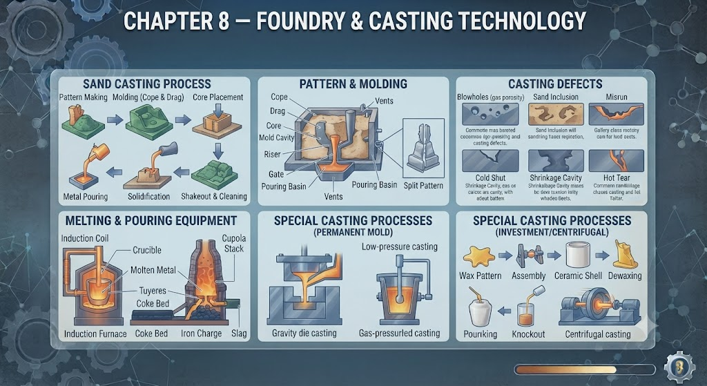
8.1 Introduction
Casting is one of the oldest and most important manufacturing processes. It is widely used for producing components having complex shapes, internal cavities, large dimensions, and intricate geometries.
Casting is extensively used in:
Automobile industries
Machine-tool industries
Railway equipment
Agricultural machinery
Pumps and valves
Engines
Turbines
Industrial machinery
Aerospace components
Defence equipment
The basic idea is simple:
Melt the metal → Pour into mould → Allow it to solidify → Remove casting
8.2 Definition of Casting
Casting is a manufacturing process in which molten material is poured into a mould cavity of the desired shape and allowed to solidify.
After solidification, the solidified product is removed from the mould and subjected to finishing operations if required.
Key Concept
Casting = Melting + Pouring + Solidification + Removal
8.3 What is a Foundry?
A foundry is a manufacturing facility where metal castings are produced.
Typical foundry operations include:
- Pattern making
- Mould preparation
- Core making
- Melting
- Pouring
- Solidification
- Shakeout
- Fettling
- Inspection
8.4 Basic Steps of Casting
The general sequence is:
Step 1 — Pattern Making
A pattern representing the desired casting is prepared.
Step 2 — Mould Making
The pattern is used to create the mould cavity.
Step 3 — Core Making
Cores are inserted when internal holes or cavities are required.
Step 4 — Melting
The metal is heated above its required melting temperature.
Step 5 — Pouring
Molten metal is poured into the mould cavity.
Step 6 — Solidification
The molten metal cools and becomes solid.
Step 7 — Shakeout
The casting is removed from the mould.
Step 8 — Fettling
Extra material such as gates, runners and risers is removed and the casting is cleaned.
Step 9 — Inspection
The finished casting is inspected for defects and dimensional accuracy.
8.5 Pattern
A pattern is a replica or representation of the desired casting used to form the mould cavity.
The pattern is not necessarily identical in dimensions to the final casting because allowances are generally provided.
8.6 Functions of a Pattern
The main functions of a pattern are:
To create the mould cavity
To reproduce the required shape
To provide necessary allowances
To facilitate moulding
To provide provisions for cores where required
8.7 Pattern Materials
Patterns may be made from:
Wood
Metal
Plastic
Plaster
Wax
Other suitable materials
Wooden Patterns
Advantages:
Cheap
Easy to manufacture
Lightweight
Easy to modify
Disadvantages:
Wear relatively quickly
Absorb moisture
Less durable than metal patterns
8.8 Metal Patterns
Common pattern metals include:
Aluminium alloys
Cast iron
Brass
Bronze
Steel
Metal patterns are generally:
Stronger
More durable
More dimensionally stable
They are suitable for larger production quantities.
8.9 Pattern Allowances
A pattern is generally modified from the exact final casting dimensions because of various manufacturing considerations.
Important pattern allowances include:
- Shrinkage allowance
- Machining allowance
- Draft allowance
- Distortion allowance
- Rapping/shake allowance
8.10 Shrinkage Allowance
Most metals shrink during solidification and cooling.
Therefore, the pattern is generally made larger than the required final casting dimensions to compensate for shrinkage.
Important
Shrinkage allowance → Positive allowance
8.11 Machining Allowance
Additional material is provided on surfaces that will later be machined.
Purpose
To allow removal of:
Surface irregularities
Oxidized material
Dimensional inaccuracies
Casting skin
Important
Machining allowance → Extra metal for machining
8.12 Draft Allowance
A slight taper is provided on pattern surfaces to facilitate easy removal of the pattern from the mould.
Without adequate draft, the mould cavity may be damaged during pattern withdrawal.
Important
Draft → Easy pattern withdrawal
8.13 Distortion Allowance
Some castings may distort during cooling because of uneven contraction.
In such cases, the pattern can be intentionally distorted in the opposite direction to compensate for expected distortion.
8.14 Shake or Rapping Allowance
When a pattern is loosened by rapping before removal, the mould cavity can become slightly larger.
Therefore, the pattern may require a negative allowance to compensate for this effect.
Important
Rapping allowance → Negative allowance
8.15 Types of Patterns
Important types include:
Single-piece pattern
Split pattern
Match-plate pattern
Cope-and-drag pattern
Loose-piece pattern
Sweep pattern
Skeleton pattern
Segmental pattern
Gated pattern
Follow-board pattern
8.16 Single-Piece Pattern
A single-piece pattern consists of one solid piece.
It is generally suitable for:
Simple shapes
Small production quantities
Simple moulding operations
8.17 Split Pattern
A split pattern is divided into two or more parts.
The division is generally made along the parting line.
Advantage
It facilitates removal of the pattern from the mould.
8.18 Match-Plate Pattern
A match-plate pattern has pattern halves mounted on opposite sides of a plate.
The plate provides the parting surface.
Application
It is particularly useful for:
Mass production of small and medium castings.
8.19 Loose-Piece Pattern
A loose-piece pattern contains detachable portions that allow difficult projections or undercuts to be moulded and the pattern to be removed.
8.20 Sweep Pattern
A sweep pattern consists of a specially shaped board that is rotated around an axis to generate a mould cavity.
It is useful for:
Large axisymmetric castings
Large simple shapes
8.21 Skeleton Pattern
A skeleton pattern consists of a framework representing the shape of the casting.
It is economical for:
Large castings produced in small quantities.
8.22 Mould
A mould is a cavity or form into which molten metal is poured to produce the desired casting.
Moulds may be:
Expendable
Permanent
8.23 Expendable Mould
An expendable mould is normally destroyed during removal of the casting.
Examples:
Sand mould
Plaster mould
Ceramic mould
Main advantage
Complex shapes can be produced relatively easily.
8.24 Permanent Mould
A permanent mould can be reused for producing many castings.
It is generally made from:
Cast iron
Steel
Other heat-resistant materials
Examples:
Permanent mould casting
Die casting
8.25 Moulding Sand
Moulding sand is used to produce the mould cavity in sand casting.
Important properties include:
- Refractoriness
- Permeability
- Strength
- Flowability
- Plasticity
- Adhesiveness
- Cohesiveness
- Collapsibility
8.26 Refractoriness
Refractoriness is the ability of moulding sand to withstand high temperature without melting or losing its essential properties.
Remember:
Refractoriness → Resistance to high temperature
8.27 Permeability
Permeability is the ability of moulding sand to allow gases and vapours to pass through it.
Why important?
During pouring and solidification, gases are generated. If they cannot escape, they can cause defects such as blowholes and gas porosity.
8.28 Strength
Moulding sand must have sufficient strength to:
Maintain mould shape
Resist erosion
Withstand handling
Resist pressure during pouring
8.29 Cohesiveness
Cohesiveness is the ability of sand particles to stick to one another.
It helps the mould maintain its shape.
8.30 Adhesiveness
Adhesiveness is the ability of moulding sand to stick to the surface of the moulding box or other surfaces.
8.31 Collapsibility
Collapsibility is the ability of moulding sand to break down or yield after solidification of the casting.
It helps prevent excessive resistance to contraction and reduces the risk of hot tearing.
8.32 Green Sand
Green sand is a commonly used moulding sand containing:
Sand
Clay/binder
Water
Other additives as required
The term green refers to the fact that the mould contains moisture and is generally used in the moist condition.
8.33 Dry Sand Mould
A dry sand mould is dried or baked before pouring.
Compared with green sand moulds, dry sand moulds generally have:
Higher strength
Better dimensional stability
Higher cost
8.34 Core
A core is used to produce internal cavities or holes in a casting.
Example
If a casting requires an internal passage, a core can be placed inside the mould cavity before pouring.
Key Concept
Core → Internal cavity
8.35 Core Print
A core print is a projection or recess provided on the pattern/moulding arrangement to locate and support the core.
8.36 Gating System
The gating system is the passage system through which molten metal flows from the pouring basin to the mould cavity.
Typical components include:
Pouring basin
Sprue
Runner
Gate
Riser
8.37 Pouring Basin
The pouring basin receives molten metal from the ladle and directs it toward the sprue.
It helps provide controlled entry of molten metal.
8.38 Sprue
The sprue is the vertical passage through which molten metal flows downward from the pouring basin.
In many conventional systems, it also helps provide a smooth flow path and may be tapered to reduce aspiration.
8.39 Runner
The runner is a horizontal or approximately horizontal passage that carries molten metal from the sprue toward the gates.
8.40 Gate
A gate is the passage through which molten metal enters the mould cavity from the runner.
8.41 Riser
A riser, also called a feeder, is a reservoir of molten metal that supplies additional metal to the casting during solidification.
Main function
Compensate for solidification shrinkage.
8.42 Casting Defects
Important casting defects include:
Blowholes
Porosity
Shrinkage cavity
Misrun
Cold shut
Hot tears
Sand inclusion
Metal penetration
Mould shift
Core shift
Fins
Scabs
8.43 Misrun
A misrun occurs when molten metal fails to completely fill the mould cavity before solidifying.
Possible causes:
Low pouring temperature
Insufficient fluidity
Slow pouring
Thin sections
Poor gating design
8.44 Cold Shut
A cold shut occurs when two streams of molten metal meet but fail to fuse properly.
It appears as a seam or line on the casting.
8.45 Shrinkage Cavity
Shrinkage cavity results from insufficient feeding of molten metal during solidification.
A properly designed riser helps reduce this defect.
8.46 Blowholes
Blowholes are relatively large cavities caused by gases trapped within the casting.
Possible causes include:
Poor mould permeability
Excess moisture
Improper venting
8.47 Hot Tears
Hot tears are cracks formed during the final stages of solidification when the metal is unable to contract freely.
Poor collapsibility of the mould/core can contribute to hot tearing.
8.48 Fettling
Fettling includes cleaning and finishing operations performed after casting removal.
Typical operations include:
Removing gates
Removing risers
Removing fins
Cleaning sand
Grinding rough surfaces
8.49 Cupola Furnace
The cupola furnace is traditionally used for melting:
Cast iron
It is a vertical shaft furnace used extensively in foundries.
8.50 Important Casting Revision
| Term | Key Point |
| Pattern | Forms mould cavity |
| Shrinkage allowance | Compensates for shrinkage |
| Machining allowance | Extra metal for machining |
| Draft allowance | Easy pattern withdrawal |
| Rapping allowance | Usually negative |
| Core | Internal cavity |
| Core print | Supports/locates core |
| Refractoriness | Withstands high temperature |
| Permeability | Allows gases to escape |
| Collapsibility | Allows mould to yield after solidification |
| Sprue | Vertical passage |
| Runner | Carries metal toward gates |
| Gate | Entry into cavity |
| Riser | Feeds metal during solidification |
| Misrun | Incomplete filling |
| Cold shut | Streams fail to fuse |
| Blowhole | Gas cavity |
| Hot tear | Crack during solidification |
| Fettling | Cleaning/finishing |
| Cupola | Traditionally melts cast iron |
Q1. Casting is a process in which molten metal is:
A. Rolled into sheets
B. Poured into a mould and solidified
C. Forged between dies
D. Cut by a tool
Answer: B. Poured into a mould and solidified
Explanation: Casting produces a component by pouring molten material into a mould cavity and allowing it to solidify.
Q2. A foundry is primarily concerned with:
A. Casting production
B. Thread cutting
C. Gear hobbing only
D. Sheet rolling only
Answer: A. Casting production
Explanation: A foundry is a facility where metal melting, moulding, pouring and casting operations are performed.
Q3. The replica used to form the mould cavity is called:
A. Core
B. Pattern
C. Riser
D. Runner
Answer: B. Pattern
Explanation: The pattern represents the shape of the desired casting and is used to form the mould cavity.
Q4. Which allowance compensates for metal contraction during cooling?
A. Draft allowance
B. Shrinkage allowance
C. Machining allowance
D. Rapping allowance
Answer: B. Shrinkage allowance
Explanation: The pattern is enlarged to compensate for contraction of the metal during solidification and cooling.
Q5. Draft allowance is provided mainly to:
A. Facilitate pattern removal
B. Increase metal hardness
C. Reduce melting temperature
D. Increase mould moisture
Answer: A. Facilitate pattern removal
Explanation: A slight taper allows the pattern to be withdrawn without damaging the mould cavity.
Q6. Machining allowance provides:
A. Extra material for subsequent machining
B. Extra gas for the mould
C. Extra water for sand
D. Extra core support
Answer: A. Extra material for subsequent machining
Explanation: Additional metal is intentionally provided on surfaces that will be machined after casting.
Q7. Rapping allowance is generally:
A. Positive
B. Negative
C. Zero in every case
D. Equal to machining allowance
Answer: B. Negative
Explanation: Rapping can enlarge the mould cavity, so a negative allowance can compensate for the effect.
Q8. A split pattern is generally divided along the:
A. Parting line
B. Sprue
C. Runner
D. Riser
Answer: A. Parting line
Explanation: The split permits easier pattern withdrawal from the mould.
Q9. Match-plate patterns are especially suitable for:
A. Mass production
B. One-off giant castings only
C. Hand forging
D. Welding
Answer: A. Mass production
Explanation: Match-plate patterns facilitate rapid and consistent mould production.
Q10. A skeleton pattern is generally economical for:
A. Large castings in small quantities
B. Mass-produced tiny castings
C. Wire drawing
D. Sheet rolling
Answer: A. Large castings in small quantities
Explanation: Only a framework is provided, reducing pattern material and manufacturing cost.
Q11. A sweep pattern is useful for producing:
A. Large axisymmetric moulds
B. Small gears only
C. Bolts only
D. Welding electrodes
Answer: A. Large axisymmetric moulds
Explanation: A shaped board is swept around an axis to generate the mould surface.
Q12. A core is primarily used to produce:
A. External surface finish
B. Internal cavity
C. Pattern draft
D. Riser height
Answer: B. Internal cavity
Explanation: Cores occupy space in the mould and create internal holes or passages.
Q13. Which property of moulding sand allows gases to escape?
A. Permeability
B. Hardness
C. Density
D. Elasticity
Answer: A. Permeability
Explanation: Permeability allows gases generated during pouring and solidification to pass through the mould.
Q14. Refractoriness of moulding sand refers to its ability to:
A. Resist high temperature
B. Absorb oil
C. Increase casting weight
D. Melt rapidly
Answer: A. Resist high temperature
Explanation: Refractory sand must withstand molten-metal temperatures without melting or deteriorating excessively.
Q15. Collapsibility of moulding sand is important because it:
A. Allows the mould to yield during casting contraction
B. Increases melting temperature
C. Prevents all gas escape
D. Makes the metal harder
Answer: A. Allows the mould to yield during casting contraction
Explanation: Good collapsibility reduces resistance to contraction and helps reduce hot tearing.
Q16. Green sand normally contains:
A. Sand, clay/binder and water
B. Only pure metal
C. Only cement
D. Only oil
Answer: A. Sand, clay/binder and water
Explanation: Green sand is commonly a moist sand mixture containing clay/binder and other additives.
Q17. The vertical passage in a conventional gating system is called:
A. Runner
B. Sprue
C. Gate
D. Riser
Answer: B. Sprue
Explanation: The sprue carries molten metal downward from the pouring basin.
Q18. The horizontal passage carrying metal from sprue to gate is called:
A. Runner
B. Core
C. Riser
D. Pattern
Answer: A. Runner
Explanation: The runner distributes molten metal from the sprue toward one or more gates.
Q19. The passage through which molten metal enters the mould cavity is the:
A. Gate
B. Core print
C. Pattern
D. Vent only
Answer: A. Gate
Explanation: The gate connects the runner to the mould cavity.
Q20. The main function of a riser is to:
A. Feed molten metal during solidification
B. Create the pattern
C. Remove the core
D. Increase permeability
Answer: A. Feed molten metal during solidification
Explanation: The riser acts as a reservoir and compensates for solidification shrinkage.
Q21. A casting defect caused by incomplete filling of the mould is:
A. Misrun
B. Blowhole
C. Hot tear
D. Scab
Answer: A. Misrun
Explanation: A misrun occurs when metal solidifies before completely filling the mould cavity.
Q22. A defect caused when two streams of molten metal fail to fuse is:
A. Cold shut
B. Shrinkage cavity
C. Blowhole
D. Sand inclusion
Answer: A. Cold shut
Explanation: A cold shut appears where separate streams meet but do not properly fuse.
Q23. A gas cavity in a casting is called:
A. Blowhole
B. Cold shut
C. Misrun
D. Hot tear
Answer: A. Blowhole
Explanation: Blowholes result from trapped gases in the casting.
Q24. A shrinkage cavity is mainly associated with:
A. Insufficient feeding during solidification
B. Excessive pattern draft only
C. Excessive mould permeability only
D. Pattern colour
Answer: A. Insufficient feeding during solidification
Explanation: As metal contracts during solidification, a sufficient supply of molten metal is needed to prevent internal voids.
Q25. Cupola furnaces are traditionally used mainly for melting:
A. Cast iron
B. Aluminium only
C. Copper only
D. Plastic
Answer: A. Cast iron
Explanation: The cupola is a vertical shaft furnace traditionally used extensively for melting cast iron in foundries.
MCQ 26–40 — Moulding Sand & Patterns
Q26. The property of moulding sand that enables it to withstand molten-metal temperature is:
A. Permeability
B. Refractoriness
C. Plasticity
D. Adhesiveness
Answer: B. Refractoriness
Explanation: Refractoriness is the ability of moulding material to withstand high temperatures without fusing or deteriorating excessively.
Q27. Which property of moulding sand is essential for the escape of gases?
A. Permeability
B. Toughness
C. Hardness
D. Elasticity
Answer: A. Permeability
Explanation: Gases generated during pouring and solidification must escape through the mould.
Q28. The ability of moulding sand to retain its shape during handling is mainly related to:
A. Strength
B. Melting point
C. Density
D. Thermal conductivity
Answer: A. Strength
Explanation: Adequate mould strength prevents the cavity from collapsing or eroding during mould handling and pouring.
Q29. Which property allows moulding sand to stick to another surface?
A. Adhesiveness
B. Permeability
C. Refractoriness
D. Collapsibility
Answer: A. Adhesiveness
Explanation: Adhesiveness is the tendency of moulding sand to adhere to the surface of the moulding box or other materials.
Q30. The ability of sand particles to stick to one another is called:
A. Cohesiveness
B. Adhesiveness
C. Permeability
D. Fluidity
Answer: A. Cohesiveness
Explanation: Cohesiveness helps individual sand grains bind together and maintain the mould shape.
Q31. Which property is desirable to allow easy breakdown of the mould after casting?
A. Collapsibility
B. Excessive hardness
C. Low refractoriness
D. Low strength
Answer: A. Collapsibility
Explanation: The mould should collapse sufficiently after solidification to allow casting removal and accommodate contraction.
Q32. Excessive moisture in moulding sand may lead to:
A. Gas-related defects
B. Increased metal strength in every case
C. Zero porosity
D. Elimination of shrinkage
Answer: A. Gas-related defects
Explanation: Excess moisture can generate steam and gases during pouring, potentially causing blowholes and other defects.
Q33. Which type of sand mould is used in a moist condition?
A. Green sand mould
B. Dry sand mould
C. Ceramic mould
D. Permanent mould
Answer: A. Green sand mould
Explanation: Green sand contains moisture and is generally used without complete drying.
Q34. The major binder traditionally used in green sand is:
A. Clay
B. Copper
C. Aluminium
D. Steel
Answer: A. Clay
Explanation: Clay provides bonding between sand grains and helps maintain mould strength.
Q35. The primary purpose of a pattern is to:
A. Produce the mould cavity
B. Melt the metal
C. Feed the casting
D. Remove slag
Answer: A. Produce the mould cavity
Explanation: The pattern represents the casting geometry and is used to create the cavity into which molten metal is poured.
Q36. A pattern is generally made larger than the required casting because of:
A. Allowances
B. Welding defects
C. Cutting forces
D. Rolling pressure
Answer: A. Allowances
Explanation: Shrinkage, machining and other allowances are incorporated into the pattern as required.
Q37. Which allowance is provided to facilitate pattern withdrawal?
A. Draft allowance
B. Shrinkage allowance
C. Machining allowance
D. Rapping allowance
Answer: A. Draft allowance
Explanation: Draft provides taper on vertical pattern surfaces, making removal easier.
Q38. The amount of draft required depends on:
A. Pattern material and moulding method
B. Colour of the pattern
C. Foundry floor area only
D. Metal electrical conductivity only
Answer: A. Pattern material and moulding method
Explanation: Pattern surface condition, moulding method, depth and material influence the required draft.
Q39. Machining allowance is generally greater for:
A. Surfaces requiring extensive machining
B. Surfaces requiring no finishing
C. Wax patterns only
D. Core prints only
Answer: A. Surfaces requiring extensive machining
Explanation: More material must be provided where greater metal removal will be required during machining.
Q40. Which pattern is divided into two parts?
A. Split pattern
B. Sweep pattern
C. Skeleton pattern
D. Single-piece pattern
Answer: A. Split pattern
Explanation: Split patterns consist of separate portions, generally corresponding to the two sides of the parting line.
MCQ 41–55 — Pattern Types & Cores
Q41. A pattern consisting of two halves mounted on opposite sides of a plate is:
A. Match-plate pattern
B. Skeleton pattern
C. Sweep pattern
D. Segmental pattern
Answer: A. Match-plate pattern
Explanation: Match-plate patterns have the pattern halves attached to a common plate and are useful for production moulding.
Q42. A skeleton pattern is particularly suitable for:
A. Large castings in small quantities
B. High-volume tiny castings
C. Wire production
D. Sheet rolling
Answer: A. Large castings in small quantities
Explanation: A framework is used instead of a solid pattern, reducing pattern cost for large, low-volume castings.
Q43. A sweep pattern generates a mould surface by:
A. Rotating a shaped board around an axis
B. Welding two plates
C. Rolling a metal sheet
D. Hammering the mould
Answer: A. Rotating a shaped board around an axis
Explanation: The sweep board produces the required mould profile as it is rotated.
Q44. A loose-piece pattern is useful when:
A. The pattern contains difficult projections or undercuts
B. No mould is required
C. Only flat surfaces are involved
D. No pattern withdrawal is needed
Answer: A. The pattern contains difficult projections or undercuts
Explanation: Detachable portions allow the pattern to be removed without damaging the mould.
Q45. A core is used primarily to produce:
A. Internal cavities
B. External dimensions
C. Pattern colour
D. Riser volume
Answer: A. Internal cavities
Explanation: Cores occupy space within the mould and create internal holes, passages and cavities.
Q46. A core is generally made from:
A. Core sand
B. Pure molten metal
C. Cutting fluid
D. Lubricating oil
Answer: A. Core sand
Explanation: Specially prepared core sand is used to produce cores with adequate strength and collapsibility.
Q47. The core is supported in the mould by:
A. Core prints
B. Runners only
C. Risers only
D. Gates only
Answer: A. Core prints
Explanation: Core prints provide locating and supporting surfaces for the core.
Q48. Core prints are generally provided on:
A. The pattern
B. The ladle
C. The furnace wall
D. The runner only
Answer: A. The pattern
Explanation: Core prints are incorporated into the pattern to create supporting recesses in the mould.
Q49. Which casting component creates an internal cylindrical hole?
A. Core
B. Riser
C. Runner
D. Sprue
Answer: A. Core
Explanation: A cylindrical core placed in the mould creates the corresponding internal hole.
Q50. The main requirement of a core is:
A. Adequate strength and collapsibility
B. Complete non-porosity under all conditions
C. Maximum hardness only
D. Zero gas permeability
Answer: A. Adequate strength and collapsibility
Explanation: The core must survive handling and pouring but should also collapse sufficiently after solidification.
Q51. Core prints are primarily used to:
A. Locate the core
B. Increase metal temperature
C. Reduce melting time
D. Remove slag
Answer: A. Locate the core
Explanation: They establish the correct position of the core inside the mould.
Q52. Which component is NOT normally part of a conventional core?
A. Core sand
B. Binder
C. Reinforcement where required
D. Molten casting metal
Answer: D. Molten casting metal
Explanation: A core is made before pouring and consists of prepared core material rather than molten casting metal.
Q53. A core should have sufficient permeability because:
A. Gases must escape
B. It must prevent all gas flow
C. It must increase casting shrinkage
D. It must act as a riser
Answer: A. Gases must escape
Explanation: Gas generated within or around the core must be vented to prevent casting defects.
Q54. Excessively strong cores may cause:
A. Difficulty in collapse after casting solidification
B. Zero casting weight
C. Increased fluidity
D. Reduced metal temperature
Answer: A. Difficulty in collapse after casting solidification
Explanation: Poor core collapsibility can restrict contraction and contribute to hot tears or difficulties during shakeout.
Q55. Which component creates an opening but does NOT normally form part of the final metal casting?
A. Core
B. Casting wall
C. Metal insert
D. Permanent feature
Answer: A. Core
Explanation: The core is removed after casting, leaving the cavity or passage.
MCQ 56–70 — Gating System & Riser
Q56. The complete passage system carrying molten metal to the mould cavity is called:
A. Gating system
B. Core system
C. Pattern system
D. Cooling system
Answer: A. Gating system
Explanation: The gating system controls the delivery of molten metal into the mould cavity.
Q57. The first receiving portion of a conventional gating system is:
A. Pouring basin
B. Riser
C. Core
D. Gate
Answer: A. Pouring basin
Explanation: The pouring basin receives molten metal from the ladle and directs it into the sprue.
Q58. The sprue is generally:
A. Vertical
B. Horizontal only
C. Circular only
D. Inclined at 90° only
Answer: A. Vertical
Explanation: In conventional gravity casting systems, the sprue is a vertical passage.
Q59. The runner is used to:
A. Distribute molten metal toward gates
B. Create internal holes
C. Remove the pattern
D. Support the core
Answer: A. Distribute molten metal toward gates
Explanation: The runner connects the sprue to one or more gates.
Q60. The gate connects the:
A. Runner and mould cavity
B. Core and riser
C. Pattern and furnace
D. Ladle and furnace
Answer: A. Runner and mould cavity
Explanation: Molten metal enters the mould cavity through the gate.
Q61. The principal function of a riser is to:
A. Supply molten metal during solidification
B. Create the mould cavity
C. Remove gases only
D. Hold the pattern
Answer: A. Supply molten metal during solidification
Explanation: The riser compensates for shrinkage as the casting solidifies.
Q62. A riser is also called a:
A. Feeder
B. Core
C. Pattern
D. Sprue
Answer: A. Feeder
Explanation: A riser feeds additional molten metal to the casting.
Q63. The riser should generally remain molten:
A. Longer than the casting section it feeds
B. Shorter than the casting in every case
C. Before pouring begins
D. Only after complete solidification
Answer: A. Longer than the casting section it feeds
Explanation: The riser must remain liquid sufficiently long to supply metal during solidification.
Q64. Which component is designed primarily to reduce shrinkage defects?
A. Riser
B. Pattern
C. Core print
D. Moulding box
Answer: A. Riser
Explanation: A properly designed feeder/riser provides molten metal to compensate for solidification contraction.
Q65. A properly designed gating system should:
A. Deliver metal smoothly and minimize turbulence
B. Maximize air entrapment
C. Prevent all metal flow
D. Increase slag formation deliberately
Answer: A. Deliver metal smoothly and minimize turbulence
Explanation: Controlled flow reduces mould erosion, air entrainment and other defects.
Q66. Excessive turbulence during pouring can increase:
A. Oxidation and air entrapment
B. Dimensional accuracy
C. Metal purity in every case
D. Core strength
Answer: A. Oxidation and air entrapment
Explanation: Turbulent flow can entrain air and oxide films and may erode mould surfaces.
Q67. A sprue may be tapered to:
A. Reduce aspiration and improve flow
B. Increase air entry
C. Stop metal flow
D. Increase casting porosity
Answer: A. Reduce aspiration and improve flow
Explanation: A properly tapered sprue helps maintain a full-flowing stream and reduces air aspiration.
Q68. The molten metal enters the mould cavity through the:
A. Gate
B. Riser only
C. Core print
D. Pattern
Answer: A. Gate
Explanation: The gate is the final passage between the runner and mould cavity.
Q69. Which sequence is correct for a conventional gravity gating system?
A. Pouring basin → Sprue → Runner → Gate → Cavity
B. Gate → Runner → Sprue → Basin → Cavity
C. Cavity → Gate → Basin → Sprue
D. Riser → Core → Runner → Basin
Answer: A. Pouring basin → Sprue → Runner → Gate → Cavity
Explanation: This represents the normal direction of molten-metal flow.
Q70. A riser is normally located:
A. At a suitable location connected to the casting
B. Inside the furnace only
C. Inside the ladle only
D. On the pattern storage rack
Answer: A. At a suitable location connected to the casting
Explanation: Its location is selected to feed regions most susceptible to shrinkage.
MCQ 71–85 — Furnaces & Casting Processes
Q71. A cupola furnace is primarily used for melting:
A. Cast iron
B. Wood
C. Plastic
D. Glass only
Answer: A. Cast iron
Explanation: Cupola furnaces have traditionally been widely used for melting cast iron in foundries.
Q72. A cupola is a:
A. Vertical shaft furnace
B. Horizontal rolling machine
C. Forging press
D. Welding machine
Answer: A. Vertical shaft furnace
Explanation: The cupola has a vertical cylindrical shaft through which charge materials descend.
Q73. Which fuel is traditionally used in a cupola furnace?
A. Coke
B. Wood only
C. Petrol only
D. Water
Answer: A. Coke
Explanation: Coke acts as a fuel and provides heat for melting in traditional cupola operation.
Q74. The charge in a cupola may include:
A. Metal, coke and flux
B. Only sand
C. Only water
D. Only clay
Answer: A. Metal, coke and flux
Explanation: The metallic charge, fuel and flux are important components of cupola operation.
Q75. The purpose of flux in a melting furnace is generally to:
A. Help form and remove slag
B. Increase pattern dimensions
C. Produce cores
D. Measure temperature only
Answer: A. Help form and remove slag
Explanation: Flux combines with impurities to form slag that can be separated from the molten metal.
Q76. Which casting process uses a reusable metal mould?
A. Permanent mould casting
B. Green sand casting only
C. Shell sand casting only
D. Plaster mould casting only
Answer: A. Permanent mould casting
Explanation: Permanent moulds are designed for repeated use.
Q77. Die casting generally uses:
A. A permanent metal die
B. A disposable wooden pattern only
C. A sand core as the entire mould
D. A paper mould
Answer: A. A permanent metal die
Explanation: Die casting uses reusable dies and is suited to high-volume production.
Q78. Die casting is particularly suitable for:
A. High-volume production of relatively small complex parts
B. One-off huge sand castings
C. Hand forging
D. Wood products
Answer: A. High-volume production of relatively small complex parts
Explanation: High production rates and good dimensional consistency are major advantages of die casting.
Q79. In pressure die casting, molten metal is introduced into the die:
A. Under pressure
B. Only by gravity
C. By hand hammering
D. Through a sand shovel
Answer: A. Under pressure
Explanation: Pressure assists rapid filling of the permanent die cavity.
Q80. Investment casting is also commonly called:
A. Lost-wax casting
B. Sand forging
C. Cold rolling
D. Drop forging
Answer: A. Lost-wax casting
Explanation: A wax pattern is surrounded by investment material and later removed before metal is cast.
Q81. Investment casting is suitable for producing:
A. Complex and accurate components
B. Only very simple plates
C. Only wooden components
D. Only rolled sheets
Answer: A. Complex and accurate components
Explanation: The process can reproduce intricate geometries and fine details.
Q82. In investment casting, the wax pattern is:
A. Removed before metal casting
B. Retained as the final metal component
C. Used as the riser
D. Used as the furnace lining
Answer: A. Removed before metal casting
Explanation: The wax is melted or otherwise removed to create the cavity into which metal is poured.
Q83. Centrifugal casting uses:
A. Centrifugal force
B. Only compressed air
C. Only chemical reaction
D. Manual hammering
Answer: A. Centrifugal force
Explanation: Rotation forces molten metal against the mould wall.
Q84. Centrifugal casting is particularly suitable for:
A. Hollow cylindrical components
B. Flat wooden plates
C. Small bolts only
D. Welding rods
Answer: A. Hollow cylindrical components
Explanation: Pipes, tubes and similar rotationally symmetric hollow components are common applications.
Q85. Shell moulding uses:
A. A thin shell of resin-bonded sand
B. Only molten metal
C. A wooden shell
D. A rubber tube
Answer: A. A thin shell of resin-bonded sand
Explanation: A heated pattern is coated with resin-bonded sand to form a relatively thin mould shell.
MCQ 86–100 — Casting Defects, Finishing & Inspection
Q86. A casting that does not completely fill the mould cavity has:
A. Misrun
B. Cold shut
C. Hot tear
D. Scab
Answer: A. Misrun
Explanation: A misrun results from premature solidification before complete cavity filling.
Q87. A cold shut is associated with:
A. Failure of two molten streams to fuse
B. Excessive riser feeding
C. Pattern removal
D. Complete mould filling
Answer: A. Failure of two molten streams to fuse
Explanation: Separate streams meet but do not form a continuous homogeneous metal connection.
Q88. Shrinkage cavities are most directly related to:
A. Solidification contraction
B. Pattern colour
C. Sand grain colour
D. Tool geometry
Answer: A. Solidification contraction
Explanation: Metal contracts during solidification, and inadequate feeding can leave internal cavities.
Q89. A blowhole is mainly caused by:
A. Trapped gas
B. Excessive machining
C. Pattern draft
D. Rapping
Answer: A. Trapped gas
Explanation: Gases that cannot escape can form cavities within the casting.
Q90. Sand inclusion means:
A. Sand particles become embedded in the casting
B. Gas becomes trapped
C. Metal fails to melt
D. Pattern expands
Answer: A. Sand particles become embedded in the casting
Explanation: Mould erosion or poor mould strength can cause sand to become incorporated into the metal.
Q91. Hot tears occur mainly because of:
A. Restrained contraction during solidification
B. Excessive machining allowance only
C. Pattern colour
D. High permeability alone
Answer: A. Restrained contraction during solidification
Explanation: If the casting cannot contract freely during late solidification, tensile stresses can cause hot tearing.
Q92. A mould shift can result in:
A. Dimensional mismatch between casting halves
B. Better dimensional accuracy
C. Increased melting point
D. Zero defects
Answer: A. Dimensional mismatch between casting halves
Explanation: Improper alignment of cope and drag can produce a mismatch at the parting line.
Q93. Core shift may cause:
A. Incorrect position of internal cavities
B. Increased metal purity
C. Reduced casting weight in every case
D. Improved dimensional accuracy
Answer: A. Incorrect position of internal cavities
Explanation: If the core moves from its intended position, internal holes or passages will be misplaced.
Q94. Fins on castings are generally caused by:
A. Metal entering unwanted gaps at mould joints
B. Low gas pressure only
C. Insufficient pattern size
D. Core permeability
Answer: A. Metal entering unwanted gaps at mould joints
Explanation: Thin projections can form when molten metal penetrates cracks or gaps in the mould.
Q95. Fettling is carried out:
A. After casting removal
B. Before pattern manufacture only
C. Before melting
D. Before mould preparation
Answer: A. After casting removal
Explanation: Fettling includes removal of gates, risers, fins, adhering sand and other unwanted material.
Q96. One operation in fettling is:
A. Removal of gates and risers
B. Pattern design
C. Core printing
D. Furnace charging only
Answer: A. Removal of gates and risers
Explanation: Gates and risers are unwanted portions attached to the casting and are removed during finishing.
Q97. Radiographic testing of castings is used mainly to detect:
A. Internal defects
B. Pattern colour
C. Surface roughness only
D. Casting weight only
Answer: A. Internal defects
Explanation: X-rays or gamma rays can reveal internal discontinuities such as porosity and inclusions.
Q98. Dye penetrant inspection is particularly useful for:
A. Surface-breaking cracks
B. Deep internal shrinkage only
C. Melting-point measurement
D. Chemical composition measurement
Answer: A. Surface-breaking cracks
Explanation: Penetrant enters open surface discontinuities and makes them visible during inspection.
Q99. Dimensional inspection of a casting is performed to:
A. Verify required dimensions and tolerances
B. Increase metal temperature
C. Remove all internal cavities
D. Change the chemical composition
Answer: A. Verify required dimensions and tolerances
Explanation: Measuring instruments are used to determine whether the casting conforms to its specified dimensions.
Q100. Which sequence correctly represents the basic casting process?
A. Pattern → Mould → Melting → Pouring → Solidification → Shakeout
B. Melting → Pattern → Welding → Rolling
C. Welding → Pattern → Forging → Casting
D. Rolling → Melting → Pattern → Grinding
Answer: A. Pattern → Mould → Melting → Pouring → Solidification → Shakeout
Explanation: This is the basic sequence from pattern preparation through removal of the solidified casting.
CHAPTER 8 — QUICK REVISION
Pattern
Pattern → Produces mould cavity
Allowances
Shrinkage → Compensates metal contraction
Machining → Extra material for machining
Draft → Easy pattern withdrawal
Distortion → Compensates expected distortion
Rapping → Generally negative
Moulding Sand
Refractoriness → Withstands heat
Permeability → Allows gas escape
Strength → Maintains mould shape
Cohesiveness → Sand grains stick together
Adhesiveness → Sand sticks to mould box
Collapsibility → Breaks down after solidification
Gating System
Pouring Basin → Sprue → Runner → Gate → Mould Cavity
Feeding
Riser → Feeds molten metal during solidification
Core
Core → Internal cavity
Important Processes
Sand casting → Expendable mould
Die casting → Permanent die + pressure
Investment casting → Lost-wax process
Centrifugal casting → Rotation/centrifugal force
Shell moulding → Resin-bonded sand shell
Cupola → Traditionally used for cast iron
Important Defects
Misrun → Incomplete filling
Cold shut → Streams fail to fuse
Blowhole → Gas cavity
Shrinkage cavity → Inadequate feeding
Hot tear → Restrained contraction
Sand inclusion → Sand trapped in casting
Mould shift → Misalignment of mould halves
Core shift → Incorrect internal cavity position
CHAPTER 9 — FORGING TECHNOLOGY
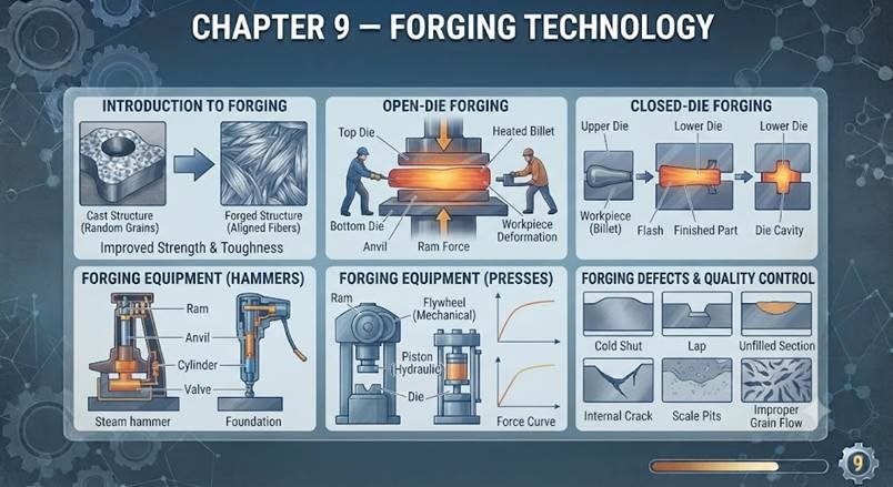
9.1 Introduction
Forging is one of the oldest metal-forming processes and is extremely important in manufacturing engineering. It is widely used when components require high strength, toughness, reliability and directional grain flow.
Forging is commonly used to manufacture:
Crankshafts
Connecting rods
Gear blanks
Spanners
Bolts
Shafts
Axles
Hooks
Wrenches
Aircraft components
Automobile components
Hand tools
9.2 Definition of Forging
Forging is a manufacturing process in which a metal workpiece is plastically deformed into the desired shape by the application of compressive forces.
The compressive force may be applied using:
Hammer
Press
Die
Mechanical equipment
Hydraulic equipment
Key Concept
Forging = Plastic deformation + Compressive force
9.3 Principle of Forging
The basic principle of forging is to bring the workpiece into a condition where it can undergo plastic deformation and then apply sufficient compressive force to obtain the desired shape.
Depending on the process, the metal may be heated before deformation.
9.4 Why Is Metal Heated Before Forging?
In hot forging, the workpiece is heated to an appropriate temperature to:
Reduce flow stress
Increase ductility
Reduce required forging force
Permit greater deformation
Refine the grain structure under suitable conditions
However, overheating must be avoided because it can cause:
Excessive grain growth
Oxidation
Burning
Loss of material properties
9.5 Types of Forging Based on Temperature
Forging can broadly be classified as:
- Hot forging
- Warm forging
- Cold forging
9.6 Hot Forging
Hot forging is carried out at a temperature sufficiently high to allow substantial plastic deformation with relatively low resistance.
Advantages
Lower forging force
Large deformation possible
Better workability
Suitable for large components
Disadvantages
Oxidation/scale formation
Lower dimensional accuracy than cold forging
Surface finish may be poorer
Heating cost
9.7 Cold Forging
Cold forging is performed at or near room temperature.
Advantages
Good dimensional accuracy
Good surface finish
No heating scale
Improved strength due to work hardening
Disadvantages
High deformation force
Limited deformation
Greater possibility of cracking in less ductile materials
Tool loads are high
9.8 Warm Forging
Warm forging is performed between conventional cold-forging and hot-forging temperature ranges.
It attempts to obtain a balance between:
Lower forming force
Better dimensional accuracy
Reduced oxidation
Improved material formability
9.9 Classification Based on Equipment
Forging can also be classified according to the equipment used:
1. Hammer Forging
The deformation is produced mainly by impact.
2. Press Forging
The deformation is produced mainly by gradual application of compressive force.
9.10 Hammer Forging
In hammer forging, the workpiece is deformed by repeated blows.
Examples of equipment include:
Drop hammer
Power hammer
Main characteristic
Impact loading
9.11 Press Forging
In press forging, deformation is produced by applying pressure gradually.
Presses may be:
Mechanical
Hydraulic
Main characteristic
Gradual compressive loading
9.12 Hammer vs Press Forging
| Hammer Forging | Press Forging |
| Impact load | Gradual load |
| Repeated blows | Continuous pressure |
| Deformation may be concentrated near surface | Deformation can penetrate deeper |
| High strain rate | Lower strain rate |
| Suitable for many die-forging operations | Suitable for large/deep deformation |
9.13 Open-Die Forging
In open-die forging, the workpiece is compressed between dies that do not completely enclose the material.
The metal is allowed to flow laterally.
Applications
Large shafts
Large rings
Heavy forgings
Large blocks
9.14 Closed-Die Forging
In closed-die forging, the workpiece is placed within shaped die cavities.
The dies approach each other and force the material to flow into the cavity.
Advantages
Complex shapes possible
Good dimensional accuracy
High production rate
Good mechanical properties
9.15 Impression-Die Forging
In impression-die forging, the dies contain impressions corresponding to the desired component geometry.
The material flows into these impressions under compressive force.
Excess material may form flash around the die parting line.
9.16 Flash
Flash is the thin excess metal that flows out between the die faces during impression-die forging.
Flash is subsequently removed by a trimming operation.
Important
Flash → Excess metal at die parting line
9.17 Flashless Forging
In flashless forging, the amount of material is carefully controlled so that the workpiece fills the die cavity without producing significant flash.
Advantages
Better material utilization
Reduced waste
Requirement
Accurate control of billet volume is important.
9.18 Upset Forging
Upset forging increases the cross-sectional area of a portion of the workpiece by reducing its length.
Example
Production of:
Bolt heads
Rivet heads
Fastener heads
Key Concept
Upsetting → Length decreases, cross-sectional area increases
9.19 Drawing Out
Drawing out is a forging operation in which:
Length increases and cross-sectional area decreases.
It is essentially the opposite of upsetting.
Key Concept
Drawing out → Length ↑, area ↓
9.20 Fullering
Fullering is used to distribute metal along the length of a workpiece.
Fullers have rounded or specially shaped surfaces.
It is often used before drawing-out operations.
9.21 Edging
Edging is used to gather or redistribute material at a particular location.
It is commonly used in die forging to prepare the required amount of material for subsequent impressions.
9.22 Bending
Bending is a forging operation in which the workpiece is given a curved or angular shape.
It is commonly used in producing:
Hooks
Links
Brackets
Certain hand tools
9.23 Punching
Punching is the operation of producing a hole by forcing a punch through a hot workpiece.
The removed material may form a slug.
9.24 Piercing
Piercing is related to producing a hole or cavity by forcing a tool into the workpiece.
The exact terminology can vary with the forging process and application.
9.25 Trimming
Trimming removes unwanted flash from a forged component.
Sequence
Forging → Flash formation → Trimming
9.26 Swaging
Swaging is a forging operation used to reduce or modify the cross-section of a workpiece by dies.
It can be performed using:
Rotary swaging
Die-based equipment
9.27 Heading
Heading is a form of upsetting used extensively in fastener manufacturing.
It is used for producing:
Bolt heads
Screw heads
Rivet heads
9.28 Coining
Coining is a precision forging operation in which very high pressure is used to produce fine surface details and accurate dimensions.
It is commonly associated with:
Coins
Medallions
Precision components
Important
Coining → High-pressure precision forging
9.29 Sizing
Sizing is a finishing forging operation used to obtain:
Better dimensional accuracy
Improved surface conformity
Only a relatively small amount of deformation is generally involved.
9.30 Roll Forging
In roll forging, the workpiece passes between rotating rolls containing shaped grooves.
The rolls progressively deform the workpiece.
Applications
Tapered components
Shafts
Axle components
Blanks
9.31 Rotary Forging
Rotary forging uses a die that applies deformation progressively over the workpiece rather than deforming the entire area simultaneously.
It can reduce required force compared with some conventional forging arrangements.
9.32 Forging Dies
Forging dies provide the surfaces against which the workpiece is deformed.
They can broadly be:
Open dies
Impression dies
Closed dies
9.33 Die Materials
Forging dies require materials having:
High strength
High toughness
Good wear resistance
Resistance to thermal fatigue
Adequate hardness at operating temperature
Common die materials include suitable tool steels and other specialized die materials.
9.34 Forging Machines
Important forging equipment includes:
Smith’s hammer
Power hammer
Drop hammer
Mechanical press
Hydraulic press
Screw press
Upset forging machine
9.35 Drop Forging
In drop forging, the upper die is raised and allowed to fall onto the workpiece, producing deformation through impact.
Important
Drop forging → Impact
9.36 Mechanical Press Forging
Mechanical presses use mechanical mechanisms such as:
Eccentric drives
Crank mechanisms
to convert rotary motion into controlled linear movement.
9.37 Hydraulic Press Forging
Hydraulic presses use hydraulic pressure to apply a controlled compressive force.
Advantages
Large force capacity
Smooth force application
Good control
Suitable for large forgings
9.38 Screw Press
A screw press uses rotational motion of a screw to generate forging force.
It can be used for:
Impression forging
Heading
Coining
Other forging operations
9.39 Advantages of Forging
Major advantages include:
- High strength
- Improved toughness
- Good fatigue resistance
- Refined grain structure under appropriate conditions
- Reduced internal defects compared with some cast products
- Favorable grain flow
- High reliability
9.40 Grain Flow in Forging
One of the major advantages of forging is the development of favorable grain flow that follows the shape of the component.
This can improve:
Strength
Fatigue resistance
Toughness
Important
Forging → Directional grain flow
9.41 Disadvantages of Forging
Limitations include:
High equipment cost
High die cost
High initial investment
Shape limitations compared with some casting processes
Material waste in some die-forging operations due to flash
High forces required for cold forging
9.42 Forging Defects
Important forging defects include:
Cracks
Laps
Cold shuts
Flakes
Internal bursts
Underfilling
Die shift
Scale pits
Improper grain flow
9.43 Forging Laps
A lap is a surface defect caused by folding of metal over itself during forging.
It can result from:
Improper metal flow
Incorrect die design
Excessive deformation in a particular region
9.44 Internal Burst
An internal burst is an internal crack that can develop because of unfavorable stress conditions during deformation.
It may occur particularly when deformation conditions and material temperature are unsuitable.
9.45 Flakes
Flakes are internal cracks associated particularly with hydrogen and delayed cracking phenomena in certain steels.
They may be detected by appropriate inspection methods.
9.46 Scale
Scale forms on the surface of hot-forged material due to oxidation at elevated temperatures.
Excessive scale can affect:
Surface quality
Dimensional accuracy
Tool life
9.47 Underfilling
Underfilling occurs when the metal does not completely fill the die impression.
Possible causes include:
Insufficient material
Improper die design
Incorrect forging temperature
Inadequate forging force
9.48 Die Shift
Die shift occurs when the two die halves are not properly aligned.
It can produce:
Mismatch
Dimensional errors
Uneven geometry
9.49 Forging Temperature
The correct forging temperature depends on:
Material
Alloy composition
Forging operation
Required deformation
Equipment
There is no single forging temperature applicable to all metals.
9.50 Important Forging Revision
| Term | Key Point |
| Forging | Plastic deformation by compressive force |
| Hot forging | High-temperature deformation |
| Warm forging | Intermediate temperature |
| Cold forging | Near-room-temperature deformation |
| Hammer forging | Impact |
| Press forging | Gradual pressure |
| Open-die | Dies do not completely enclose workpiece |
| Closed-die | Workpiece deforms within die cavity |
| Flash | Excess metal at die parting line |
| Upsetting | Length ↓, area ↑ |
| Drawing out | Length ↑, area ↓ |
| Fullering | Distributes metal |
| Edging | Gathers/redistributes metal |
| Bending | Produces angular/curved shape |
| Punching | Produces hole |
| Trimming | Removes flash |
| Heading | Produces fastener heads |
| Coining | High-pressure precision forging |
| Sizing | Improves dimensional accuracy |
| Roll forging | Deformation between rotating rolls |
| Drop forging | Impact |
| Hydraulic press | Controlled large compressive force |
| Lap | Folded-over metal defect |
| Flake | Internal crack associated with hydrogen |
| Underfill | Incomplete die filling |
| Die shift | Die misalignment |
Q1. Forging is primarily a:
A. Casting process
B. Metal forming process
C. Machining process
D. Joining process
Answer: B. Metal forming process
Explanation: Forging changes the shape of metal through plastic deformation rather than removing material.
Practice
Q2. The principal force in forging is:
A. Tensile force
B. Compressive force
C. Shear force only
D. Bending force only
Answer: B. Compressive force
Explanation: Forging primarily involves plastic deformation under compressive loading.
Q3. A major advantage of forging is:
A. Favorable grain flow
B. High internal porosity
C. No deformation
D. Very low strength
Answer: A. Favorable grain flow
Explanation: Proper forging can produce grain flow that follows the component geometry, improving mechanical performance.
Q4. Hot forging is performed at:
A. Elevated temperature
B. Only absolute zero
C. Below the freezing point of the metal
D. Room temperature only
Answer: A. Elevated temperature
Explanation: The workpiece is heated sufficiently to facilitate plastic deformation.
Q5. Cold forging is generally carried out:
A. Near room temperature
B. Above the melting point
C. Inside a furnace only
D. At boiling temperature
Answer: A. Near room temperature
Explanation: Cold forging occurs without heating the workpiece to conventional hot-forging temperatures.
Q6. The major advantage of hot forging over cold forging is:
A. Lower deformation force
B. No oxidation
C. Higher dimensional accuracy in every case
D. Zero heating requirement
Answer: A. Lower deformation force
Explanation: Heating reduces the flow stress of many metals and makes large deformation easier.
Q7. Cold forging can improve strength mainly through:
A. Work hardening
B. Melting
C. Casting
D. Annealing
Answer: A. Work hardening
Explanation: Plastic deformation at low temperature can increase strength through strain/work hardening.
Q8. Hammer forging primarily applies:
A. Impact loading
B. Hydrostatic loading only
C. Tensile loading
D. Thermal loading only
Answer: A. Impact loading
Explanation: Hammer forging deforms the workpiece through repeated or single high-energy blows.
Q9. Press forging applies force:
A. Gradually
B. Only through explosion
C. Only through cutting
D. Without contact
Answer: A. Gradually
Explanation: A press applies compressive force over a relatively controlled stroke.
Q10. Open-die forging uses dies that:
A. Do not completely enclose the workpiece
B. Completely surround the workpiece in every case
C. Are made only of sand
D. Never contact the workpiece
Answer: A. Do not completely enclose the workpiece
Explanation: Material is allowed to flow laterally between relatively simple die surfaces.
Q11. Closed-die forging is also associated with:
A. Impression forging
B. Sand casting
C. Rolling only
D. Welding
Answer: A. Impression forging
Explanation: Shaped die impressions force the workpiece into a desired geometry.
Q12. Excess metal formed between impression-die faces is called:
A. Flash
B. Scale
C. Slag
D. Core
Answer: A. Flash
Explanation: Flash is excess material squeezed out around the die parting line.
Q13. Flash is generally removed by:
A. Trimming
B. Annealing only
C. Casting
D. Rolling
Answer: A. Trimming
Explanation: Trimming removes unwanted flash from the forged component.
Q14. In upsetting, the length of the workpiece generally:
A. Decreases
B. Increases
C. Remains unchanged in every case
D. Becomes zero
Answer: A. Decreases
Explanation: Upsetting increases cross-sectional area by reducing the axial length.
Q15. In drawing out, the cross-sectional area generally:
A. Decreases
B. Increases
C. Becomes infinite
D. Always remains constant
Answer: A. Decreases
Explanation: Drawing out increases length while reducing cross-sectional area.
Q16. Bolt heads are commonly produced by:
A. Upset forging/heading
B. Sand casting only
C. Rolling only
D. Extrusion only
Answer: A. Upset forging/heading
Explanation: Heading increases material at one end to form the head of a bolt, screw or rivet.
Q17. Fullering is primarily used to:
A. Distribute metal along the workpiece
B. Remove flash
C. Produce a casting cavity
D. Measure hardness
Answer: A. Distribute metal along the workpiece
Explanation: Fullers help spread and redistribute metal before subsequent forging operations.
Q18. Edging is mainly used to:
A. Gather material in a desired region
B. Remove scale
C. Produce holes only
D. Melt the workpiece
Answer: A. Gather material in a desired region
Explanation: Edging prepares the billet by concentrating material where required for subsequent die impressions.
Q19. Coining is characterized by:
A. Very high pressure and fine detail reproduction
B. Very low pressure
C. Sand moulding
D. Gas welding
Answer: A. Very high pressure and fine detail reproduction
Explanation: Coining is a precision forging operation used to reproduce fine surface details.
Q20. Sizing is primarily used to improve:
A. Dimensional accuracy
B. Melting temperature
C. Chemical composition
D. Gas content
Answer: A. Dimensional accuracy
Explanation: Sizing provides a small final deformation to improve dimensional conformity.
Q21. Roll forging uses:
A. Rotating rolls
B. Sand moulds
C. Welding electrodes
D. Cutting tools only
Answer: A. Rotating rolls
Explanation: The workpiece passes between shaped rotating rolls and is progressively deformed.
Q22. A hydraulic forging press applies force using:
A. Hydraulic pressure
B. Centrifugal force only
C. Gravity only
D. Magnetic force only
Answer: A. Hydraulic pressure
Explanation: Hydraulic systems generate controlled compressive forces suitable for large forgings.
Q23. A major disadvantage of cold forging is:
A. High forming force
B. Poor surface finish in every case
C. High oxidation
D. No work hardening
Answer: A. High forming force
Explanation: Materials have higher flow stress at lower temperatures, requiring greater forming loads.
Q24. A forging defect caused by folding of metal over itself is:
A. Lap
B. Blowhole
C. Shrinkage cavity
D. Sand inclusion
Answer: A. Lap
Explanation: A lap is produced when flowing metal folds and the fold is not properly welded together.
Q25. Flakes in steel forgings are associated particularly with:
A. Hydrogen
B. Nitrogen only
C. Carbon dioxide only
D. Water vapour in moulding sand only
Answer: A. Hydrogen
Explanation: Flakes are internal cracks associated with hydrogen-related delayed cracking in susceptible steels.
A. Forging Fundamentals — MCQs 26–40
Q26. Which process produces a component by plastic deformation under compressive force?
A. Casting
B. Forging
C. Welding
D. Grinding
Answer: B. Forging
Explanation: Forging changes the shape of a workpiece by plastic deformation using compressive forces.
Practice
Q27. Which of the following is generally NOT a characteristic advantage of forging?
A. Improved mechanical properties
B. Favorable grain flow
C. High internal porosity
D. Good fatigue strength
Answer: C. High internal porosity
Explanation: Forging generally reduces or closes certain internal discontinuities rather than intentionally producing porosity.
Q28. Forged components are commonly preferred for critical applications because of:
A. High reliability
B. High porosity
C. Very low strength
D. Poor fatigue resistance
Answer: A. High reliability
Explanation: Properly forged components can provide excellent strength, toughness and fatigue performance.
Q29. Which of the following is a typical forged component?
A. Crankshaft
B. Glass bottle
C. Plastic film
D. Ceramic tile
Answer: A. Crankshaft
Explanation: Crankshafts are commonly manufactured by forging because of the strength and fatigue resistance required.
Q30. The deformation in forging is mainly:
A. Elastic
B. Plastic
C. Thermal only
D. Chemical only
Answer: B. Plastic
Explanation: Permanent shape change occurs when the material is plastically deformed.
Q31. The flow stress of a metal generally decreases when the metal is:
A. Heated for hot forging
B. Cooled to extremely low temperature
C. Hardened completely
D. Made brittle
Answer: A. Heated for hot forging
Explanation: Increasing temperature generally reduces resistance to plastic deformation, within the appropriate forging range.
Q32. Excessive heating of a forging billet may cause:
A. Grain growth and burning
B. Improved properties in every case
C. Zero oxidation
D. Complete elimination of defects
Answer: A. Grain growth and burning
Explanation: Excessive temperature can cause undesirable metallurgical changes and oxidation.
Q33. The oxide layer formed during hot forging is called:
A. Scale
B. Flash
C. Slag
D. Burr
Answer: A. Scale
Explanation: Scale forms because the hot metal reacts with oxygen in the atmosphere.
Q34. Hot forging is particularly useful when:
A. Large deformation is required
B. No deformation is required
C. Only surface coating is required
D. Only cutting is required
Answer: A. Large deformation is required
Explanation: Heating reduces resistance to deformation and allows substantial plastic deformation.
Q35. Which forging method generally provides better dimensional accuracy?
A. Cold forging
B. Very high-temperature forging
C. Rough open-die forging only
D. Manual hammering only
Answer: A. Cold forging
Explanation: Cold forging can produce excellent dimensional accuracy and surface finish, although tooling and forming forces are higher.
Q36. One important effect of cold working is:
A. Work hardening
B. Grain melting
C. Complete removal of residual stress
D. Reduction of strength in every case
Answer: A. Work hardening
Explanation: Plastic deformation below the recrystallization temperature generally increases strength and hardness.
Q37. A limitation of cold forging is:
A. High forming load
B. Low dimensional accuracy
C. High oxidation
D. Need for melting
Answer: A. High forming load
Explanation: Higher flow stress at low temperature increases the required forging force.
Q38. Warm forging is positioned approximately between:
A. Hot and cold forging
B. Casting and welding
C. Rolling and machining
D. Grinding and turning
Answer: A. Hot and cold forging
Explanation: Warm forging provides an intermediate-temperature forming condition.
Q39. The main purpose of heating a billet before hot forging is to:
A. Reduce deformation resistance
B. Increase brittleness
C. Prevent all grain movement
D. Eliminate plastic deformation
Answer: A. Reduce deformation resistance
Explanation: Heating makes plastic deformation easier and reduces the required forging force.
Q40. Forging is generally classified as a:
A. Bulk deformation process
B. Joining process
C. Surface coating process
D. Material removal process
Answer: A. Bulk deformation process
Explanation: Forging is one of the major bulk metal-forming processes, along with rolling and extrusion.
B. Hammer and Press Forging — MCQs 41–55
Q41. The main characteristic of hammer forging is:
A. Impact
B. Continuous melting
C. Tensile loading
D. Chemical reaction
Answer: A. Impact
Explanation: Hammer forging uses repeated or single blows to deform the workpiece.
Q42. The main characteristic of press forging is:
A. Gradual application of force
B. Impact only
C. No die contact
D. Tensile loading
Answer: A. Gradual application of force
Explanation: Presses apply force progressively through a controlled stroke.
Q43. Which machine is commonly associated with drop forging?
A. Drop hammer
B. Lathe
C. Milling machine
D. Shaper
Answer: A. Drop hammer
Explanation: A drop hammer uses the potential energy of a raised ram to produce an impact blow.
Q44. In a drop hammer, the ram is:
A. Raised and dropped onto the workpiece
B. Rotated continuously
C. Used as a cutting tool
D. Cooled below room temperature
Answer: A. Raised and dropped onto the workpiece
Explanation: The falling ram provides impact energy to deform the workpiece.
Q45. Hydraulic presses are especially suitable for:
A. Large forgings
B. Only very small screws
C. Cutting thin sheets
D. Grinding surfaces
Answer: A. Large forgings
Explanation: Hydraulic presses can generate very large, controlled forces.
Q46. A mechanical forging press commonly converts rotary motion into:
A. Linear motion
B. Chemical energy
C. Thermal energy only
D. Electrical energy only
Answer: A. Linear motion
Explanation: Crank and eccentric mechanisms convert rotary motion into reciprocating ram movement.
Q47. A screw press generates forging force through:
A. Screw motion
B. Centrifugal force only
C. Gas pressure only
D. Magnetic force
Answer: A. Screw motion
Explanation: Rotational movement of the screw produces controlled axial movement and forging force.
Q48. Compared with a hammer, a press generally applies force:
A. More gradually
B. Only instantaneously
C. Without contacting the workpiece
D. Through tension
Answer: A. More gradually
Explanation: Press forging involves controlled squeezing rather than repeated impact blows.
Q49. Press forging can provide:
A. Better control of deformation
B. No deformation
C. Only surface hardening
D. Only cutting
Answer: A. Better control of deformation
Explanation: The press stroke and force can be controlled more precisely than repeated hammer blows.
Q50. Which equipment is most closely associated with impact forging?
A. Power hammer
B. Hydraulic press
C. Screw jack only
D. Lathe
Answer: A. Power hammer
Explanation: Power hammers deliver repeated impact blows to deform the workpiece.
Q51. A major advantage of hydraulic presses is:
A. High force capacity
B. No force generation
C. Only intermittent operation
D. Inability to control force
Answer: A. High force capacity
Explanation: Hydraulic systems can generate and control very large compressive loads.
Q52. Hammer forging is particularly associated with:
A. High strain rate
B. Zero strain rate
C. Tensile deformation only
D. No contact pressure
Answer: A. High strain rate
Explanation: The rapid impact produces a relatively high deformation rate.
Q53. Press forging generally has a:
A. Lower deformation rate than hammer forging
B. Higher impact rate than hammer forging
C. Zero deformation rate
D. Purely thermal deformation
Answer: A. Lower deformation rate than hammer forging
Explanation: Presses apply deformation more gradually.
Q54. The energy of a drop hammer is mainly associated with:
A. Falling ram
B. Cutting speed
C. Coolant pressure
D. Electric resistance
Answer: A. Falling ram
Explanation: The elevated ram possesses potential energy that is converted into impact energy during the drop.
Q55. Which machine is suitable for controlled high-force forging?
A. Hydraulic press
B. Hand file
C. Drill press only
D. Grinding wheel
Answer: A. Hydraulic press
Explanation: Hydraulic presses provide large and controllable compressive forces.
C. Open-Die and Closed-Die Forging — MCQs 56–70
Q56. In open-die forging, the workpiece is:
A. Compressed between relatively simple dies
B. Completely enclosed in a die cavity
C. Melted inside the die
D. Cut by a milling cutter
Answer: A. Compressed between relatively simple dies
Explanation: The dies do not completely surround the workpiece.
Q57. Open-die forging is particularly suitable for:
A. Large components
B. Mass production of tiny precision screws only
C. Plastic bottles
D. Thin wires only
Answer: A. Large components
Explanation: Large shafts, rings and heavy components are commonly produced using open-die forging.
Q58. Which of the following is a typical open-die forging application?
A. Large shaft
B. Plastic cup
C. Glass lens
D. Paper clip
Answer: A. Large shaft
Explanation: Open-die forging is widely used for large shafts and other heavy components.
Q59. In closed-die forging, the workpiece is:
A. Forced into shaped die impressions
B. Allowed to remain molten
C. Machined by a drill
D. Rolled into a sheet
Answer: A. Forced into shaped die impressions
Explanation: Die cavities determine the final geometry.
Q60. Impression-die forging is another term closely associated with:
A. Closed-die forging
B. Sand casting
C. Wire drawing
D. Arc welding
Answer: A. Closed-die forging
Explanation: Impression dies contain shaped cavities into which the metal flows.
Q61. Flash in impression-die forging forms mainly at the:
A. Die parting line
B. Furnace bottom
C. Core print
D. Billet centre only
Answer: A. Die parting line
Explanation: Excess material is squeezed between the die faces at the parting region.
Q62. The principal disadvantage of flash formation is:
A. Material wastage
B. Zero deformation
C. Complete absence of strength
D. Elimination of grain flow
Answer: A. Material wastage
Explanation: The flash must subsequently be removed, resulting in some material loss.
Q63. Flashless forging requires accurate control of:
A. Billet volume
B. Furnace colour
C. Die paint only
D. Coolant colour
Answer: A. Billet volume
Explanation: The billet must contain approximately the correct amount of material to fill the die without producing significant flash.
Q64. Closed-die forging is generally more suitable than open-die forging for:
A. Complex shapes in production quantities
B. Extremely large simple blocks only
C. Rough preliminary shaping only
D. Melting operations
Answer: A. Complex shapes in production quantities
Explanation: Shaped die cavities can produce relatively complex geometries repeatedly.
Q65. Open-die forging provides:
A. Greater freedom of metal flow
B. Complete confinement of material
C. No deformation
D. Only tensile stress
Answer: A. Greater freedom of metal flow
Explanation: The material can flow laterally beyond the die surfaces.
Q66. A forging operation that increases cross-section while reducing length is:
A. Upsetting
B. Drawing out
C. Rolling
D. Trimming
Answer: A. Upsetting
Explanation: Axial compression causes the material to spread laterally.
Q67. A forging operation that increases length while reducing cross-section is:
A. Drawing out
B. Upsetting
C. Heading
D. Coining
Answer: A. Drawing out
Explanation: The material is elongated while its cross-sectional area decreases.
Q68. Which operation is commonly used to prepare material distribution before impression forging?
A. Fullering
B. Grinding
C. Drilling
D. Lapping
Answer: A. Fullering
Explanation: Fullering helps spread material to appropriate locations before subsequent die operations.
Q69. Edging is primarily used to:
A. Gather material
B. Remove flash
C. Produce surface cracks
D. Melt the billet
Answer: A. Gather material
Explanation: Edging concentrates material in selected regions of the billet.
Q70. Which operation removes flash after impression-die forging?
A. Trimming
B. Fullering
C. Edging
D. Upsetting
Answer: A. Trimming
Explanation: Trimming cuts away the unwanted flash surrounding the forged component.
D. Forging Operations — MCQs 71–85
Q71. Heading is essentially a form of:
A. Upsetting
B. Drawing
C. Rolling
D. Bending only
Answer: A. Upsetting
Explanation: Heading increases the cross-sectional area at one end of a workpiece.
Q72. Which component is commonly produced by heading?
A. Bolt head
B. Large casting mould
C. Sheet-metal die
D. Cutting fluid
Answer: A. Bolt head
Explanation: Heading is widely used for bolts, screws and rivets.
Q73. Coining involves:
A. High-pressure deformation for fine detail
B. Low-pressure casting
C. Gas welding
D. Sand moulding
Answer: A. High-pressure deformation for fine detail
Explanation: Coining reproduces detailed impressions on the surface of the workpiece.
Q74. Which process is commonly associated with manufacturing coins?
A. Coining
B. Fullering
C. Drawing out
D. Edging
Answer: A. Coining
Explanation: Coining is a precision forging process used to reproduce detailed designs.
Q75. Sizing is generally a:
A. Finishing operation
B. Melting operation
C. Casting operation
D. Joining operation
Answer: A. Finishing operation
Explanation: Sizing provides small final deformation to achieve dimensional accuracy.
Q76. Swaging is used primarily to:
A. Modify or reduce cross-section using dies
B. Melt the metal
C. Remove internal gases
D. Produce a mould cavity
Answer: A. Modify or reduce cross-section using dies
Explanation: Swaging shapes the workpiece by die action, often reducing or changing its cross-section.
Q77. Roll forging uses:
A. Rotating grooved rolls
B. Stationary sand moulds
C. Cutting tools
D. Welding electrodes
Answer: A. Rotating grooved rolls
Explanation: The rolls contain grooves that progressively deform the workpiece.
Q78. Roll forging is particularly useful for:
A. Producing tapered sections
B. Producing glass products
C. Cutting threads only
D. Casting hollow sand moulds
Answer: A. Producing tapered sections
Explanation: Roll forging can efficiently produce tapered shafts and similar components.
Q79. Bending in forging is used to produce:
A. Curved or angular shapes
B. Internal porosity
C. Molten metal
D. Sand cores only
Answer: A. Curved or angular shapes
Explanation: Controlled plastic deformation changes the axis or shape of the workpiece.
Q80. Punching in forging is used to:
A. Produce a hole
B. Remove scale only
C. Increase billet length only
D. Produce a riser
Answer: A. Produce a hole
Explanation: A punch is driven into or through the workpiece to create an opening.
Q81. Fullering tools generally have:
A. Rounded or specially shaped surfaces
B. Only flat cutting edges
C. Grinding wheels
D. Drill points
Answer: A. Rounded or specially shaped surfaces
Explanation: Their shape facilitates redistribution of material.
Q82. Drawing out is commonly performed to:
A. Increase length
B. Reduce length
C. Produce flash
D. Create a mould cavity
Answer: A. Increase length
Explanation: Drawing out elongates the workpiece and reduces its cross-sectional area.
Q83. Upsetting is commonly used to produce:
A. Enlarged ends
B. Long thin sheets
C. Internal casting cavities
D. Sand moulds
Answer: A. Enlarged ends
Explanation: Axial compression produces a larger cross-section, making it useful for bolt and rivet heads.
Q84. Which operation is associated with removing unwanted metal from the edge of a forging?
A. Trimming
B. Fullering
C. Edging
D. Drawing
Answer: A. Trimming
Explanation: Trimming removes flash and other unwanted excess material.
Q85. Which operation is used to improve the final dimensional accuracy of a forging with relatively small deformation?
A. Sizing
B. Fullering
C. Bending
D. Drawing out
Answer: A. Sizing
Explanation: Sizing is a finishing operation used to bring a forged part closer to the required dimensions.
E. Forging Defects, Dies & Quality — MCQs 86–100
Q86. A forging lap is caused by:
A. Folding of metal over itself
B. Gas trapped in a mould
C. Shrinkage of molten metal
D. Sand inclusion
Answer: A. Folding of metal over itself
Explanation: A lap occurs when material folds during metal flow and the fold is not properly consolidated.
Q87. Which defect is associated with internal cracking in certain steels due to hydrogen?
A. Flakes
B. Flash
C. Misrun
D. Scab
Answer: A. Flakes
Explanation: Flakes are internal cracks associated with hydrogen and delayed cracking mechanisms in susceptible steels.
Q88. Underfilling means:
A. The die cavity is not completely filled
B. Excess flash is produced
C. The forging is completely machined
D. The billet is melted
Answer: A. The die cavity is not completely filled
Explanation: Underfilling leaves portions of the die impression unfilled.
Q89. One possible cause of underfilling is:
A. Insufficient billet material
B. Excessive correct material volume
C. Perfect die design
D. Proper forging temperature
Answer: A. Insufficient billet material
Explanation: If there is inadequate material, the die cavity cannot be completely filled.
Q90. Die shift is primarily caused by:
A. Misalignment of die halves
B. Excessive permeability
C. Gas in moulding sand
D. Riser failure
Answer: A. Misalignment of die halves
Explanation: Incorrect die alignment produces mismatch between the two sides of the forging.
Q91. Scale formation during hot forging is mainly due to:
A. Oxidation
B. Hydrogen absorption only
C. Plastic deformation alone
D. Machining
Answer: A. Oxidation
Explanation: The hot metal reacts with oxygen and forms oxide scale.
Q92. Excessive scale can adversely affect:
A. Surface quality
B. Only electrical conductivity
C. Only colour
D. Nothing
Answer: A. Surface quality
Explanation: Scale can produce rough surfaces and may become embedded or cause dimensional issues.
Q93. A good forging die should have:
A. High wear resistance
B. Very low strength
C. Very low toughness
D. Poor thermal stability
Answer: A. High wear resistance
Explanation: Dies experience repeated mechanical and thermal loading and therefore require good wear resistance.
Q94. Forging dies are commonly made from:
A. Suitable tool steels
B. Wood only
C. Pure rubber
D. Glass
Answer: A. Suitable tool steels
Explanation: Tool steels and specialized die materials provide the required strength, toughness and wear resistance.
Q95. The grain flow in a properly forged component generally:
A. Follows the component geometry
B. Disappears completely
C. Becomes random in every region
D. Is unrelated to deformation
Answer: A. Follows the component geometry
Explanation: Controlled metal flow can produce favorable directional grain structure.
Q96. Favorable grain flow can improve:
A. Fatigue resistance
B. Porosity
C. Casting shrinkage
D. Mould permeability
Answer: A. Fatigue resistance
Explanation: Appropriate grain flow can enhance mechanical performance, especially under cyclic loading.
Q97. Which forging process generally produces no flash by design?
A. Flashless forging
B. Conventional impression forging
C. Open-die forging
D. Drop forging with uncontrolled billet volume
Answer: A. Flashless forging
Explanation: Flashless forging uses accurately controlled material volume to fill the die without significant flash formation.
Q98. A major economic advantage of flashless forging is:
A. Better material utilization
B. Increased scrap
C. Lower dimensional accuracy
D. Increased oxidation
Answer: A. Better material utilization
Explanation: Since little or no flash is generated, less material is wasted.
Q99. Which of the following is generally a disadvantage of forging?
A. High die cost
B. High strength
C. Favorable grain flow
D. Good fatigue resistance
Answer: A. High die cost
Explanation: Forging dies can be expensive, particularly for complex closed-die components.
Q100. Which statement best describes forging?
A. Metal is plastically shaped primarily by compressive forces
B. Metal is always melted and poured into a mould
C. Material is removed entirely by cutting
D. Two pieces are joined by an adhesive
Answer: A. Metal is plastically shaped primarily by compressive forces
Explanation: This is the fundamental principle of forging.
CHAPTER 9 — EXAM REVISION SHEET
Remember these relationships:
Forging → Compressive force
Hot forging → Lower flow stress + large deformation
Cold forging → Better accuracy + work hardening
Hammer → Impact
Press → Gradual force
Open die → Large/simple/heavy components
Closed die → Complex production components
Flash → Excess metal
Trimming → Flash removal
Upsetting → Length ↓, Area ↑
Drawing out → Length ↑, Area ↓
Fullering → Distribute metal
Edging → Gather metal
Heading → Bolt/rivet/screw heads
Coining → Fine details + high pressure
Sizing → Final dimensional improvement
Roll forging → Rotating rolls
Lap → Folded metal
Flake → Hydrogen-related internal crack
Underfill → Incomplete die filling
Die shift → Die misalignment
Grain flow → Important forging advantage
CHAPTER 10 — SHEET METAL WORKING
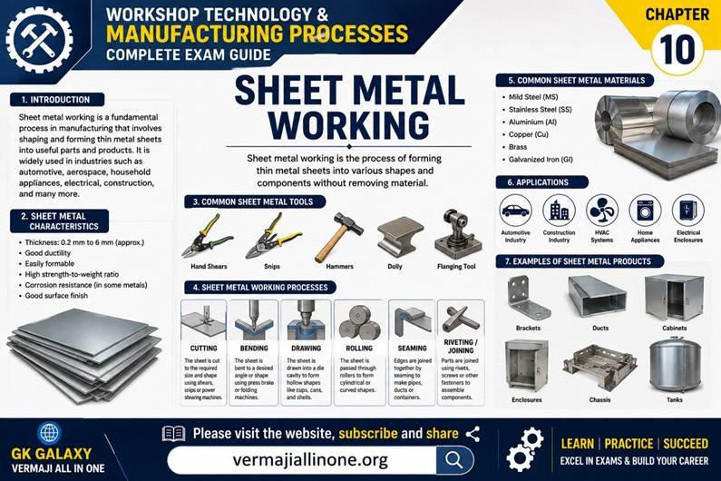
10.1 Introduction
Sheet metal working is a manufacturing process in which thin metal sheets are cut, bent, formed, or otherwise shaped into useful components.
It is extensively used in:
Automobile bodies
Aircraft structures
Railway coaches
Electrical panels
Kitchen equipment
Metal containers
Computer cabinets
Refrigerators
Air-conditioner bodies
Automobile fuel tanks
Roofing products
Sheet-metal operations are generally characterized by high production rate, relatively low material wastage in suitable processes, and good dimensional repeatability.
10.2 Definition of Sheet Metal Working
Sheet metal working is a manufacturing process in which sheet or strip metal is subjected to operations such as cutting, bending and forming to produce the required shape.
The material is generally processed without removing large quantities of material in the form of chips.
Key Concept
Sheet Metal Working = Cutting + Bending + Forming
10.3 Important Terms in Sheet Metal Working
Before studying individual operations, the following terms are essential.
1. Sheet
A relatively thin, flat piece of metal.
2. Strip
A long, narrow metal sheet supplied in continuous or coil form.
3. Blank
A piece of sheet metal cut to the required shape for a subsequent forming operation.
4. Punch
The tool that moves relative to the die and performs cutting or forming.
5. Die
The stationary or supporting tool containing the required opening or forming surface.
6. Clearance
The difference or gap between the punch and die dimensions.
7. Burr
A sharp, unwanted projection produced along a cut edge.
8. Slug
The piece of material removed during a punching operation.
10.4 Classification of Sheet-Metal Operations
Sheet-metal operations can broadly be divided into:
A. Cutting Operations
Shearing
Blanking
Punching
Perforating
Notching
Slitting
Trimming
B. Bending Operations
V-bending
U-bending
Angle bending
Flanging
Hemming
Curling
C. Drawing/Forming Operations
Deep drawing
Stretch forming
Spinning
Embossing
Bulging
10.5 Shearing
Shearing is the process of cutting sheet metal by applying shear forces using cutting edges.
The material is separated without producing a conventional saw-cut.
Basic Principle
Punch/upper blade + lower blade/die + sheet → separation
10.6 Blanking
In blanking, the piece that is cut out is the required product.
The remaining sheet is scrap, subject to layout and process conditions.
Most Important Rule
Blanking → Blank is the product
10.7 Punching
In punching, the hole produced in the sheet is the required feature, while the removed piece is generally considered scrap.
Most Important Rule
Punching → Hole is the product
The removed portion is called the slug.
10.8 Blanking vs Punching
| Blanking | Punching |
| Cut-out piece is useful | Hole is useful |
| Blank is the product | Sheet with hole is the product |
| Cut-out is called blank | Removed piece is called slug |
| Remaining sheet is generally scrap | Slug is generally scrap |
Easy Memory Trick
Blanking → Blank = useful
Punching → Hole = useful
10.9 Perforating
Perforating produces a number of holes in a sheet by punching.
Examples:
- Perforated screens
- Ventilation panels
- Filters
- Decorative sheets
10.10 Notching
Notching removes material from the edge of a sheet.
It may be used to prepare the sheet for:
Bending
Joining
Forming
10.11 Slitting
Slitting separates sheet or strip material along a line, usually using rotary cutters or knives.
It is widely used to produce narrower strips from wider coils.
10.12 Trimming
Trimming removes unwanted material from a previously formed or drawn component.
Example
Removing excess flange from a deep-drawn cup.
10.13 Bending
Bending is a sheet-metal operation in which the sheet is plastically deformed around an axis.
The thickness generally remains approximately constant, although some thinning can occur depending on the operation and severity.
10.14 V-Bending
In V-bending, the sheet is bent using a V-shaped die.
It is one of the most common sheet-metal bending operations.
10.15 U-Bending
In U-bending, the sheet is formed into a U-shaped cross-section.
10.16 Flanging
Flanging produces a flange or rim along the edge of a sheet or component.
Applications include:
Joining
Stiffening
Assembly
Structural reinforcement
10.17 Hemming
Hemming folds the edge of a sheet over itself.
It is commonly used to:
Remove sharp edges
Improve stiffness
Improve appearance
Provide safe edges
Automobile body panels commonly use hemming.
10.18 Curling
Curling rolls the edge of a sheet into a curved or tubular form.
It can be used to:
Strengthen edges
Provide rounded edges
Prepare components for assembly
10.19 Springback
Springback is the elastic recovery that occurs after the bending force is removed.
As a result, the final angle may differ slightly from the die angle.
Important
Springback → Elastic recovery after unloading
10.20 Why Does Springback Occur?
During bending, the sheet experiences both:
Plastic deformation
Elastic deformation
When the load is removed, the elastic portion recovers, causing the sheet to partially return toward its original shape.
10.21 Methods of Reducing Springback
Springback can be reduced by techniques such as:
Over-bending
Bottoming
Coining
Proper tool design
Appropriate process parameters
10.22 Neutral Axis
During bending, a region exists within the sheet where the longitudinal strain is approximately zero.
This is called the neutral axis.
Important
Material outside the neutral axis on the bending side experiences tension, while material on the opposite side experiences compression.
10.23 Bend Allowance
Bend allowance represents the length of material required along the neutral region for a bend.
It is used when calculating the flat length of a sheet-metal component before bending.
10.24 Deep Drawing
Deep drawing is a sheet-metal forming process in which a flat blank is drawn into a die cavity using a punch to produce a cup-shaped or hollow component.
Typical products:
Cups
Cans
Utensils
Automobile components
Fuel tanks
Cylindrical containers
10.25 Main Components of Deep Drawing
Important components include:
- Punch
- Die
- Blank holder
- Blank
- Die cavity
10.26 Function of Blank Holder
The blank holder helps prevent unwanted wrinkling of the flange during deep drawing.
Important
Blank holder → Controls wrinkling
However, excessive blank-holder force can restrict material flow and increase the possibility of tearing.
10.27 Drawing Ratio
The drawing ratio is commonly expressed as:
where:
= blank diameter
= punch diameter
A larger drawing ratio generally indicates a more severe drawing operation.
10.28 Deep Drawing Defects
Important defects include:
Wrinkling
Tearing
Earing
Surface scratches
Excessive thinning
10.29 Wrinkling
Wrinkling is the formation of unwanted folds or wrinkles, commonly in the flange region.
A suitable blank-holder force helps control it.
10.30 Tearing
Tearing occurs when the tensile stress becomes too high and the sheet fails.
It may occur near the punch radius or other highly stressed regions.
Possible causes:
Excessive drawing ratio
Excessive blank-holder force
Small punch radius
Inadequate lubrication
Material limitations
10.31 Earing
Earing refers to the formation of ears or uneven peaks around the rim of a deep-drawn cup.
It is primarily related to anisotropy of the sheet material.
Important
Earing → Plastic anisotropy
10.32 Lubrication in Deep Drawing
Lubrication helps:
Reduce friction
Reduce drawing force
Reduce tool wear
Improve surface finish
Facilitate material flow
10.33 Stretch Forming
In stretch forming, a sheet is clamped at its edges and stretched over a form block or die.
The sheet undergoes tensile deformation.
It is widely used in:
Aircraft structures
Large curved panels
Aerospace components
10.34 Spinning
Metal spinning forms a circular sheet blank over a rotating mandrel using a tool.
It is suitable for:
Conical components
Cylindrical components
Hemispherical components
Reflectors
Utensils
10.35 Embossing
Embossing produces raised or recessed patterns on sheet metal.
Applications include:
Decorative panels
Name plates
Identification markings
Stiffening patterns
10.36 Coining in Sheet Metal
In sheet-metal forming, coining involves localized high-pressure deformation to produce accurate details or impressions.
It can also be used to improve dimensional control in certain operations.
10.37 Punch and Die Clearance
Clearance is the difference between the dimensions of the punch and die, considering the appropriate cutting relationship.
Correct clearance is extremely important.
Too little clearance may cause:
Excessive force
Increased tool wear
Poor cutting conditions
Too much clearance may cause:
Large burr
Poor edge quality
Excessive deformation
10.38 Burr
A burr is a sharp projection left on the edge after a cutting operation.
Burr formation is influenced by:
Tool sharpness
Clearance
Material properties
Tool alignment
Sheet thickness
10.39 Press Tools
Sheet-metal operations are often performed using press tools.
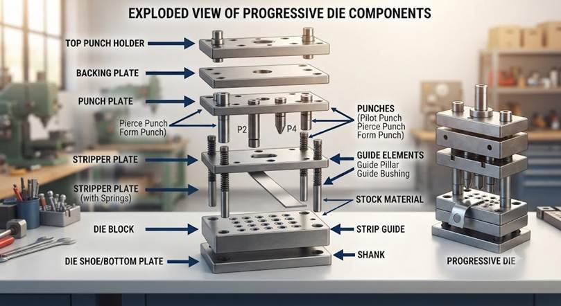
A typical press tool consists of:
Punch
Die
Punch plate
Die block
Guide elements
Stripper
Back plate
Other supporting components
10.40 Stripper
A stripper helps remove the sheet or strip from the punch after the cutting operation.
It can also help hold the material in position.
10.41 Progressive Die
A progressive die performs multiple operations at different stations as the strip moves through the die.
Advantages:
High production rate
Automation
Good repeatability
10.42 Compound Die
A compound die performs multiple cutting operations in a single stroke at one station.
This is an important distinction.
Remember:
Progressive die → Multiple stations
Compound die → Multiple operations, one station
10.43 Combination Die
A combination die performs both:
Cutting
Forming
operations in the same die during the manufacturing sequence.
10.44 Single-Operation Die
A single-operation die performs one principal operation at a time.
It is simpler than progressive or compound tooling.
10.45 Sheet-Metal Materials
Common sheet-metal materials include:
Mild steel
Stainless steel
Aluminium
Copper
Brass
Zinc
Titanium alloys
Material selection depends on:
Formability
Strength
Corrosion resistance
Weight
Cost
Surface requirements
10.46 Formability
Formability is the ability of a sheet material to undergo the required deformation without failure.
Good formability is particularly important for:
Deep drawing
Stretch forming
Bending
10.47 Ductility and Sheet Forming
Ductile materials generally undergo larger plastic deformation before fracture.
Therefore, ductility is an important consideration in sheet-metal forming.
10.48 Advantages of Sheet-Metal Working
Major advantages include:
High production rate
Good repeatability
Low material wastage in suitable operations
Good surface finish
Suitable for automation
Suitable for mass production
Lightweight components can be produced
10.49 Limitations
Limitations include:
Tooling cost
Springback
Wrinkling
Tearing
Burr formation
Material limitations
Requirement for accurate tooling
10.50 QUICK REVISION TABLE
| Term | Key Point |
| Sheet | Thin flat metal |
| Blank | Cut piece used as product/forming starting piece |
| Punch | Moving forming/cutting tool |
| Die | Supporting/forming tool |
| Clearance | Gap between punch and die |
| Blanking | Blank is useful |
| Punching | Hole is useful |
| Slug | Removed piece in punching |
| Perforating | Multiple holes |
| Notching | Removes material from edge |
| Slitting | Separates strip/sheet longitudinally |
| Trimming | Removes unwanted material |
| Bending | Plastic deformation around an axis |
| Springback | Elastic recovery |
| Hemming | Folding sheet edge |
| Flanging | Producing a flange |
| Deep drawing | Flat blank → hollow component |
| Blank holder | Controls wrinkling |
| Earing | Due to anisotropy |
| Stretch forming | Sheet stretched over form |
| Spinning | Sheet formed over rotating mandrel |
| Embossing | Raised/recessed pattern |
| Burr | Sharp projection on cut edge |
| Progressive die | Multiple stations |
| Compound die | Multiple operations, one station |
Q1. Sheet-metal working primarily involves:
A. Cutting, bending and forming
B. Melting only
C. Welding only
D. Grinding only
Answer: A. Cutting, bending and forming
Explanation: Sheet-metal manufacturing uses various cutting and forming operations to produce components from sheets and strips.
Practice
Q2. In blanking, the:
A. Cut-out piece is the product
B. Hole is the product
C. Slug is always the product
D. Die is the product
Answer: A. Cut-out piece is the product
Explanation: The blank separated from the sheet is the required component.
Q3. In punching, the useful product is generally:
A. The hole in the sheet
B. The slug
C. The punch
D. The die
Answer: A. The hole in the sheet
Explanation: Punching creates a hole; the removed slug is generally scrap.
Q4. The removed piece in punching is called:
A. Slug
B. Blank
C. Riser
D. Flash
Answer: A. Slug
Explanation: The material removed during punching is called a slug.
Q5. Which operation produces multiple holes in a sheet?
A. Perforating
B. Drawing
C. Bending
D. Hemming
Answer: A. Perforating
Explanation: Perforating involves producing a series of holes in sheet material.
Q6. Notching removes material from:
A. The edge of a sheet
B. The centre of a billet only
C. A forging die
D. A casting riser
Answer: A. The edge of a sheet
Explanation: Notching is commonly used to remove material from the edge before subsequent forming or joining.
Q7. Slitting is used to:
A. Separate sheet or strip along a line
B. Produce deep cups
C. Produce raised patterns
D. Produce bolt heads
Answer: A. Separate sheet or strip along a line
Explanation: Slitting divides wide sheet or strip into narrower sections.
Q8. Which operation removes excess material from a formed sheet-metal component?
A. Trimming
B. Drawing
C. Stretching
D. Embossing
Answer: A. Trimming
Explanation: Trimming removes unwanted portions from a previously formed component.
Q9. Bending primarily produces:
A. Plastic deformation around an axis
B. Melting
C. Casting
D. Welding
Answer: A. Plastic deformation around an axis
Explanation: Bending changes the shape of the sheet without intentionally removing material.
Q10. Springback is caused by:
A. Elastic recovery
B. Melting
C. Plastic flow only
D. Oxidation
Answer: A. Elastic recovery
Explanation: After the bending load is removed, the elastically deformed portion recovers.
Q11. Springback can be compensated by:
A. Over-bending
B. Increasing burrs
C. Reducing all tooling accuracy
D. Removing the die
Answer: A. Over-bending
Explanation: The sheet can be intentionally bent beyond the desired final angle to compensate for elastic recovery.
Q12. During bending, the neutral axis has approximately:
A. Zero longitudinal strain
B. Maximum tensile strain
C. Maximum compressive strain
D. Zero thickness
Answer: A. Zero longitudinal strain
Explanation: The neutral region separates tensile and compressive deformation zones.
Q13. The outer region of a bent sheet generally experiences:
A. Tension
B. Compression only
C. No deformation
D. Melting
Answer: A. Tension
Explanation: The outer fibres are stretched during bending.
Q14. The inner region of a bent sheet generally experiences:
A. Compression
B. Tension only
C. No stress
D. Melting
Answer: A. Compression
Explanation: The inner fibres are compressed during bending.
Q15. Deep drawing converts a flat blank into:
A. A cup-like or hollow component
B. A weld joint
C. A gear tooth
D. A forged shaft only
Answer: A. A cup-like or hollow component
Explanation: A punch draws the blank into a die cavity.
Q16. The main function of a blank holder in deep drawing is to:
A. Control wrinkling
B. Produce a riser
C. Melt the blank
D. Cut threads
Answer: A. Control wrinkling
Explanation: The blank holder controls the flange and helps prevent excessive wrinkling.
Q17. Excessive blank-holder force can:
A. Restrict material flow and promote tearing
B. Always eliminate tearing
C. Eliminate friction completely
D. Produce casting porosity
Answer: A. Restrict material flow and promote tearing
Explanation: Excessive restraint prevents the sheet from flowing properly into the die cavity.
Q18. Earing in deep drawing is primarily caused by:
A. Anisotropy
B. Casting shrinkage
C. Gas porosity
D. Welding current
Answer: A. Anisotropy
Explanation: Directional differences in plastic properties can produce uneven ear formation.
Q19. The drawing ratio is commonly defined as:
A. Blank diameter / Punch diameter
B. Punch diameter / Blank thickness
C. Sheet thickness / Blank diameter
D. Die diameter / Sheet thickness
Answer: A. Blank diameter / Punch diameter
Explanation: A common drawing ratio is .
Q20. Lubrication during deep drawing helps to:
A. Reduce friction
B. Increase tool wear
C. Increase tearing intentionally
D. Eliminate material flow
Answer: A. Reduce friction
Explanation: Proper lubrication facilitates material flow and reduces friction and tool wear.
Q21. Stretch forming involves:
A. Stretching sheet over a form
B. Punching holes only
C. Cutting strips only
D. Forging a billet
Answer: A. Stretching sheet over a form
Explanation: The sheet is clamped and stretched over a die or form block.
Q22. Metal spinning generally uses:
A. A rotating mandrel
B. A stationary sand mould
C. A casting riser
D. A forging hammer only
Answer: A. A rotating mandrel
Explanation: A circular sheet blank is formed against a rotating mandrel.
Q23. Embossing produces:
A. Raised or recessed patterns
B. Internal casting cavities
C. Forging flash
D. Welding beads
Answer: A. Raised or recessed patterns
Explanation: Embossing is used to create surface details and can also improve stiffness.
Q24. A burr is:
A. A sharp projection on a cut edge
B. A deep drawing ratio
C. A type of die
D. A sheet-metal blank
Answer: A. A sharp projection on a cut edge
Explanation: Burrs are unwanted projections produced during cutting operations.
Q25. Excessive punch-die clearance can result in:
A. Larger burr and poorer edge quality
B. Zero burr
C. Perfect edge quality in every case
D. No cutting force
Answer: A. Larger burr and poorer edge quality
Explanation: Incorrectly large clearance can produce excessive deformation and a rougher cut edge.
A. Cutting Operations — MCQs 26–40
Q26. In a shearing operation, the sheet is separated primarily by:
A. Tensile stress
B. Shear stress
C. Bending stress only
D. Thermal stress
Answer: B. Shear stress
Explanation: Cutting of sheet metal occurs mainly through shearing deformation followed by fracture.
Q27. Which operation produces a useful cut-out piece called a blank?
A. Punching
B. Blanking
C. Slitting
D. Notching
Answer: B. Blanking
Explanation: In blanking, the separated portion is the desired product.
Q28. In punching, the removed portion is called:
A. Blank
B. Slug
C. Flash
D. Burr
Answer: B. Slug
Explanation: The slug is the piece removed from the sheet during punching.
Q29. In blanking, the die opening generally determines the:
A. Blank size
B. Punch colour
C. Sheet hardness
D. Lubricant viscosity
Answer: A. Blank size
Explanation: In conventional blanking, the die opening determines the external dimensions of the blank.
Q30. In punching, the punch generally determines the:
A. Hole size
B. Sheet thickness
C. Die hardness
D. Blank material
Answer: A. Hole size
Explanation: The punch size corresponds closely to the desired hole dimensions, with allowance for cutting clearance.
Q31. The gap between punch and die is called:
A. Draft
B. Clearance
C. Rake
D. Allowance only
Answer: B. Clearance
Explanation: Clearance is provided between the cutting edges of the punch and die.
Q32. Proper punch-die clearance is important for:
A. Cutting force and edge quality
B. Colour of sheet
C. Melting point only
D. Electrical resistance only
Answer: A. Cutting force and edge quality
Explanation: Clearance strongly affects cutting force, burr formation, tool life and cut-edge quality.
Q33. If punch-die clearance is too small, it may result in:
A. Excessive cutting force and tool wear
B. No deformation
C. Zero tool load
D. Perfect operation in every case
Answer: A. Excessive cutting force and tool wear
Explanation: Insufficient clearance increases the resistance to shearing and may accelerate tool damage.
Q34. If punch-die clearance is excessively large, it may cause:
A. Large burr and poor edge quality
B. Zero burr
C. No fracture
D. No cutting action
Answer: A. Large burr and poor edge quality
Explanation: Excessive clearance causes more deformation before fracture and generally produces a rougher edge with a larger burr.
Q35. The sharp projection left after sheet-metal cutting is called:
A. Burr
B. Slug
C. Blank
D. Flash
Answer: A. Burr
Explanation: Burr is unwanted material projecting from the cut edge.
Q36. Burr formation is influenced by:
A. Clearance
B. Tool sharpness
C. Material properties
D. All of the above
Answer: D. All of the above
Explanation: Clearance, tool condition and workpiece properties all influence burr formation.
Q37. A large number of holes produced simultaneously or sequentially in sheet metal is known as:
A. Perforating
B. Forging
C. Drawing
D. Rolling
Answer: A. Perforating
Explanation: Perforating creates multiple holes in sheet material.
Q38. Notching is primarily used to:
A. Remove material from the sheet edge
B. Produce a deep cup
C. Stretch the sheet
D. Produce a forged shaft
Answer: A. Remove material from the sheet edge
Explanation: Notching removes portions from the edge of a sheet or strip.
Q39. Slitting is generally performed to:
A. Divide sheet or strip into narrower sections
B. Produce deep-drawn cups
C. Produce raised patterns
D. Produce bolt heads
Answer: A. Divide sheet or strip into narrower sections
Explanation: Slitting separates sheet or strip along a predetermined line.
Q40. Which operation removes unwanted material from a previously formed component?
A. Trimming
B. Stretch forming
C. Bending
D. Spinning
Answer: A. Trimming
Explanation: Trimming removes excess material from the edges of formed or drawn parts.
B. Bending Operations — MCQs 41–55
Q41. During sheet-metal bending, the outer fibres are generally subjected to:
A. Tension
B. Compression
C. No strain
D. Shear only
Answer: A. Tension
Explanation: The outer region of a bent sheet is stretched.
Q42. During bending, the inner fibres are generally subjected to:
A. Compression
B. Tension
C. No stress
D. Thermal expansion only
Answer: A. Compression
Explanation: The inner region is compressed during bending.
Q43. The neutral axis during bending is the region where longitudinal strain is approximately:
A. Zero
B. Maximum
C. Infinite
D. Equal to tensile strain
Answer: A. Zero
Explanation: The neutral axis separates the tensile and compressive regions.
Q44. Springback is:
A. Elastic recovery after unloading
B. Plastic deformation during loading
C. Melting after heating
D. Fracture during cutting
Answer: A. Elastic recovery after unloading
Explanation: The elastic portion of deformation recovers when the bending force is removed.
Q45. Springback generally causes the final bend angle to:
A. Differ from the tooling angle
B. Become exactly zero
C. Become infinite
D. Remain unchanged in all cases
Answer: A. Differ from the tooling angle
Explanation: Elastic recovery changes the final geometry after unloading.
Q46. One method of compensating for springback is:
A. Over-bending
B. Increasing sheet thickness indefinitely
C. Eliminating all tooling
D. Reducing all deformation
Answer: A. Over-bending
Explanation: The workpiece is bent beyond the desired angle so that elastic recovery brings it closer to the target.
Q47. V-bending uses:
A. V-shaped die
B. Circular saw
C. Flat grinding wheel
D. Sand mould
Answer: A. V-shaped die
Explanation: A punch presses the sheet into a V-shaped die.
Q48. U-bending produces:
A. U-shaped cross-section
B. Circular hole
C. Flat blank only
D. Threaded shaft
Answer: A. U-shaped cross-section
Explanation: The sheet is bent around a U-shaped forming geometry.
Q49. Flanging is used to produce:
A. A flange or rim
B. A hole only
C. A casting cavity
D. A forging flash
Answer: A. A flange or rim
Explanation: Flanging forms a projecting edge or rim on the sheet.
Q50. Hemming involves:
A. Folding the sheet edge over
B. Punching a circular hole
C. Stretching a sheet over a die only
D. Cutting a strip longitudinally
Answer: A. Folding the sheet edge over
Explanation: Hemming folds an edge to improve safety, stiffness and appearance.
Q51. Automobile body panels commonly use:
A. Hemming
B. Sand casting
C. Forging only
D. Thread rolling only
Answer: A. Hemming
Explanation: Hemming is widely used to create safe and stiff edges on sheet-metal body panels.
Q52. Curling is used to:
A. Roll the edge into a curved form
B. Punch holes
C. Remove a slug
D. Produce a forging die
Answer: A. Roll the edge into a curved form
Explanation: Curling produces a rounded or tubular edge.
Q53. Bend allowance is related to:
A. Length of material required for a bend
B. Punch hardness
C. Sheet colour
D. Tool temperature only
Answer: A. Length of material required for a bend
Explanation: Bend allowance helps determine the flat pattern length needed to produce the required bent geometry.
Q54. Which property is particularly desirable for severe sheet forming?
A. Good ductility
B. Extreme brittleness
C. Very low formability
D. Zero plasticity
Answer: A. Good ductility
Explanation: Ductility allows significant plastic deformation before fracture.
Q55. Which factor can influence springback?
A. Material properties
B. Sheet thickness
C. Bend geometry
D. All of the above
Answer: D. All of the above
Explanation: Springback depends on material strength, elastic modulus, thickness, bend radius and process conditions.
C. Deep Drawing — MCQs 56–75
Q56. Deep drawing is used to produce:
A. Hollow cup-like components
B. Gear teeth by cutting
C. Welded joints
D. Forging dies
Answer: A. Hollow cup-like components
Explanation: A flat sheet blank is drawn into a die cavity by a punch.
Q57. The main tools in deep drawing are:
A. Punch, die and blank holder
B. Drill, reamer and tap
C. Hammer and anvil only
D. Grinding wheel and dresser
Answer: A. Punch, die and blank holder
Explanation: These components control the deformation and material flow during drawing.
Q58. The blank holder primarily prevents:
A. Wrinkling
B. All friction
C. Elastic recovery
D. Punch movement
Answer: A. Wrinkling
Explanation: The blank holder restrains the flange and reduces buckling/wrinkling.
Q59. Excessive blank-holder pressure can increase the possibility of:
A. Tearing
B. Wrinkling only
C. No deformation
D. Casting porosity
Answer: A. Tearing
Explanation: Excessive restraint makes it difficult for the blank to flow into the die.
Q60. The drawing ratio is generally expressed as:
A. Blank diameter / Punch diameter
B. Punch diameter / Blank diameter
C. Sheet thickness / Blank diameter
D. Die radius / Punch radius
Answer: A. Blank diameter / Punch diameter
Explanation: A common drawing ratio is .
Q61. A higher drawing ratio generally means:
A. More severe drawing
B. No deformation
C. Less material movement
D. Only cutting
Answer: A. More severe drawing
Explanation: A larger ratio means the blank must undergo greater reduction to reach the required cup diameter.
Q62. A common defect in deep drawing is:
A. Wrinkling
B. Flash only
C. Sand inclusion
D. Welding porosity
Answer: A. Wrinkling
Explanation: Compressive stresses in the flange can cause wrinkles.
Q63. Tearing in deep drawing occurs mainly due to:
A. Excessive tensile stress
B. Zero tensile stress
C. Excessive compressive stress only
D. No deformation
Answer: A. Excessive tensile stress
Explanation: If the material cannot withstand the tensile stresses generated during drawing, it may tear.
Q64. Earing is associated with:
A. Anisotropy of sheet metal
B. Casting temperature
C. Welding current
D. Forging flash
Answer: A. Anisotropy of sheet metal
Explanation: Directional variation in plastic properties causes uneven deformation around the rim.
Q65. Ears are generally observed around the:
A. Rim of a drawn cup
B. Centre of the punch only
C. Bottom of the die only
D. Tool shank
Answer: A. Rim of a drawn cup
Explanation: Anisotropic deformation creates peaks or ears around the cup circumference.
Q66. Lubrication in deep drawing primarily reduces:
A. Friction
B. Ductility
C. Sheet thickness
D. Blank diameter
Answer: A. Friction
Explanation: Lubrication facilitates sliding between the sheet and tooling.
Q67. Proper lubrication can also reduce:
A. Tool wear
B. Material flow
C. Formability
D. Blank holding
Answer: A. Tool wear
Explanation: Lower friction reduces heat and mechanical wear at the tool-workpiece interface.
Q68. A very small punch radius may increase the tendency for:
A. Tearing
B. Earing elimination
C. Zero deformation
D. Slitting
Answer: A. Tearing
Explanation: A sharp punch radius can produce severe localized deformation and stress concentration.
Q69. A deep-drawn cylindrical cup is produced using:
A. Punch and die
B. Welding electrode
C. Lathe tool
D. Milling cutter
Answer: A. Punch and die
Explanation: The punch pushes the blank into the die cavity.
Q70. The flange region of a deep-drawn blank mainly undergoes:
A. Compressive circumferential stress
B. Pure tension only
C. No deformation
D. Melting
Answer: A. Compressive circumferential stress
Explanation: The flange is subjected to circumferential compression, which can cause wrinkling.
Q71. The wall of a deep-drawn cup is mainly subjected to:
A. Tensile stress in the drawing direction
B. Pure compression only
C. No stress
D. Shear only
Answer: A. Tensile stress in the drawing direction
Explanation: Material is pulled into the die cavity, producing tensile stresses along the wall/drawing direction.
Q72. The blank holder force should be:
A. Properly controlled
B. Always maximum possible
C. Always zero
D. Independent of material and process
Answer: A. Properly controlled
Explanation: Too little force promotes wrinkling, while too much force can restrict flow and promote tearing.
Q73. One important application of deep drawing is manufacturing:
A. Metal cups and cans
B. Forging hammers
C. Cutting inserts only
D. Grinding wheels
Answer: A. Metal cups and cans
Explanation: Deep drawing is widely used for hollow sheet-metal containers.
Q74. If a deep drawing operation exceeds the material’s forming capability, the likely result is:
A. Failure/tearing
B. Perfect forming
C. No deformation
D. Automatic annealing
Answer: A. Failure/tearing
Explanation: Excessive deformation can exceed the forming limit of the sheet.
Q75. Intermediate annealing may be required in:
A. Multi-stage severe drawing
B. Simple punching only
C. Slitting only
D. Single light bending only
Answer: A. Multi-stage severe drawing
Explanation: Annealing can restore ductility between drawing stages when significant work hardening has accumulated.
D. Press Tools and Dies — MCQs 76–90
Q76. A progressive die performs operations:
A. At multiple stations
B. Only outside the press
C. Without a strip
D. Only during casting
Answer: A. At multiple stations
Explanation: The strip advances from one station to the next, with different operations performed at successive positions.
Q77. A compound die performs multiple operations:
A. At one station in one stroke
B. At many independent machines only
C. Without a punch
D. Only during forging
Answer: A. At one station in one stroke
Explanation: Multiple cutting operations can be completed simultaneously at a single die station.
Q78. A combination die performs:
A. Cutting and forming operations
B. Only grinding
C. Only welding
D. Only rolling
Answer: A. Cutting and forming operations
Explanation: Combination dies combine cutting and forming functions.
Q79. A stripper in a press tool is used mainly to:
A. Remove material from the punch
B. Heat the sheet
C. Melt the die
D. Increase sheet thickness
Answer: A. Remove material from the punch
Explanation: The stripper separates the sheet/strip from the punch after the stroke.
Q80. A major advantage of progressive dies is:
A. High production rate
B. No tooling requirement
C. No material movement
D. Very low repeatability
Answer: A. High production rate
Explanation: Progressive dies are highly suitable for automated mass production.
Q81. Progressive dies are particularly suitable for:
A. Mass production
B. One-off handmade components only
C. Casting sand preparation
D. Welding repair only
Answer: A. Mass production
Explanation: Multiple operations can be integrated into a continuous strip-processing sequence.
Q82. The part that performs cutting or forming movement in a press tool is the:
A. Punch
B. Die shoe only
C. Guide post
D. Back plate
Answer: A. Punch
Explanation: The punch moves relative to the die and performs the intended operation.
Q83. The stationary component receiving the punch during cutting is generally the:
A. Die
B. Punch
C. Stripper
D. Guide pin
Answer: A. Die
Explanation: The die provides the opening or forming surface against which the sheet is deformed/cut.
Q84. Guide elements in a press tool help to:
A. Maintain alignment
B. Increase sheet thickness
C. Melt the punch
D. Produce lubricants
Answer: A. Maintain alignment
Explanation: Guide posts and bushings help maintain proper alignment between punch and die.
Q85. Poor punch-die alignment can cause:
A. Uneven clearance and tool damage
B. Perfect cutting
C. Zero wear
D. No force requirement
Answer: A. Uneven clearance and tool damage
Explanation: Misalignment changes the clearance around the cutting edges and can accelerate wear.
Q86. The die block primarily:
A. Provides the die opening/forming cavity
B. Supplies hydraulic pressure
C. Measures sheet hardness
D. Acts as lubricant
Answer: A. Provides the die opening/forming cavity
Explanation: The die block contains the working die geometry.
Q87. A press tool is generally mounted on a:
A. Press machine
B. Lathe only
C. Furnace only
D. Welding table only
Answer: A. Press machine
Explanation: Press tools are designed to perform sheet-metal cutting and forming operations in presses.
Q88. The selection of punch-die clearance depends significantly on:
A. Sheet material and thickness
B. Paint colour
C. Operator height
D. Machine room size
Answer: A. Sheet material and thickness
Explanation: Different materials and thicknesses require appropriate clearances for efficient cutting.
Q89. Excessive tool wear can result in:
A. Poor dimensional and edge quality
B. Perfect burr-free cutting indefinitely
C. Zero force
D. Increased ductility of the sheet
Answer: A. Poor dimensional and edge quality
Explanation: Worn cutting edges degrade the quality and dimensional accuracy of the cut.
Q90. A major advantage of press-tool production is:
A. Repeatability
B. Extremely low production rate
C. No need for tooling
D. No dimensional control
Answer: A. Repeatability
Explanation: Properly designed press tools can produce large numbers of consistent components.
E. Forming, Defects and Applications — MCQs 91–100
Q91. Stretch forming is widely used in:
A. Aerospace components
B. Sand casting
C. Brick making
D. Welding electrodes
Answer: A. Aerospace components
Explanation: Stretch forming is suitable for producing large curved sheet structures used in aircraft and aerospace applications.
Q92. In stretch forming, the sheet is:
A. Stretched over a form
B. Poured into a mould
C. Forged between hammers
D. Machined by a cutter
Answer: A. Stretched over a form
Explanation: The sheet is held under tension while being wrapped around the forming surface.
Q93. Metal spinning generally produces:
A. Axisymmetric components
B. Random irregular castings
C. Flat bars only
D. Welded joints
Answer: A. Axisymmetric components
Explanation: Spinning is particularly suitable for circular and rotationally symmetric components.
Q94. A common product made by metal spinning is:
A. Reflector
B. Gear tooth
C. Connecting rod
D. Welding electrode
Answer: A. Reflector
Explanation: Reflectors and other conical, cylindrical and hemispherical components can be produced by spinning.
Q95. Embossing is mainly used to:
A. Produce raised or recessed details
B. Produce deep holes only
C. Remove all sheet material
D. Produce casting cores
Answer: A. Produce raised or recessed details
Explanation: Embossing creates surface patterns, markings or stiffening features.
Q96. Wrinkling in deep drawing is primarily associated with:
A. Compressive stresses in the flange
B. Pure tensile stress only
C. Melting
D. Welding
Answer: A. Compressive stresses in the flange
Explanation: Circumferential compression can make the flange unstable and cause wrinkles.
Q97. Tearing in deep drawing is primarily associated with:
A. Excessive tensile stress
B. Zero stress
C. Only compressive stress
D. Sand inclusion
Answer: A. Excessive tensile stress
Explanation: If the tensile stress exceeds the material’s forming capability, fracture can occur.
Q98. Which defect is strongly related to sheet-metal anisotropy?
A. Earing
B. Burr
C. Flash
D. Die shift
Answer: A. Earing
Explanation: Directional plastic properties cause uneven height around the rim of a drawn cup.
Q99. Which of the following is an important advantage of sheet-metal working?
A. High production rate
B. High chip generation in every operation
C. Extremely poor repeatability
D. No possibility of automation
Answer: A. High production rate
Explanation: Press-based sheet-metal processes are highly suitable for mass production and automation.
Q100. Which statement is correct?
A. Blanking produces a useful blank, while punching produces a useful hole
B. Blanking and punching always have identical products
C. Punching produces only forged components
D. Blanking is a welding operation
Answer: A. Blanking produces a useful blank, while punching produces a useful hole
Explanation: This distinction is one of the most important concepts in sheet-metal cutting operations.
CHAPTER 10 — ONE-PAGE EXAM REVISION
Cutting
Shearing → Separation by shear
Blanking → Blank is product
Punching → Hole is product
Slug → Removed piece during punching
Perforating → Multiple holes
Notching → Edge material removal
Slitting → Dividing strip/sheet
Trimming → Excess material removal
Bending
Bending → Plastic deformation
Outer surface → Tension
Inner surface → Compression
Neutral axis → Approximately zero longitudinal strain
Springback → Elastic recovery
Hemming → Edge folded over
Flanging → Flange formation
Deep Drawing
Blank → Flat starting sheet
Punch → Pushes blank into die
Blank holder → Controls wrinkling
Drawing ratio → Blank diameter / Punch diameter
Wrinkling → Compressive flange stress
Tearing → Excessive tensile stress
Earing → Anisotropy
Lubrication → Reduces friction
Dies
Progressive die → Multiple stations
Compound die → Multiple operations at one station
Combination die → Cutting + forming
Stripper → Removes sheet from punch
CHAPTER 11 — METAL CUTTING & MACHINE TOOLS
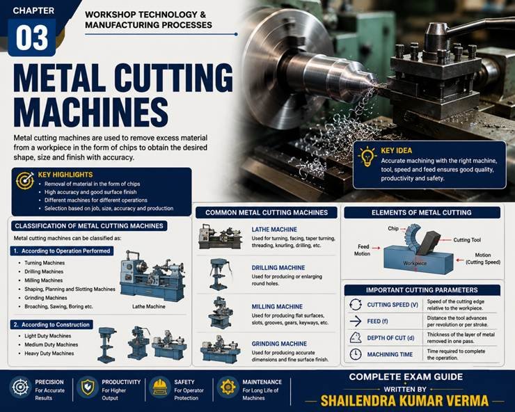
11.1 Introduction
Metal cutting is one of the most important manufacturing processes in workshop technology. It is a material-removal process in which unwanted material is removed from a workpiece in the form of chips to obtain the required:
Shape
Size
Accuracy
Surface finish
Metal cutting is performed using cutting tools mounted on machine tools such as:
Lathe
Drilling machine
Shaper
Planer
Slotter
Milling machine
Grinding machine
11.2 Definition of Metal Cutting
Metal cutting is a manufacturing process in which a cutting tool removes unwanted material from a workpiece in the form of chips to produce the required geometry and surface finish.
Key Concept
Metal Cutting = Workpiece + Cutting Tool + Relative Motion + Material Removal
11.3 Definition of Machine Tool
A machine tool is a power-driven machine used to hold and move a cutting tool and/or workpiece to perform machining operations accurately.
Examples:
Lathe
Milling machine
Drilling machine
Shaper
Planer
Slotter
Grinding machine
11.4 Machining
Machining is the controlled removal of material from a workpiece using a cutting tool.
Examples:
Turning
Drilling
Milling
Shaping
Planning
Boring
Reaming
11.5 Cutting Tool
A cutting tool is a device having one or more cutting edges designed to remove material from a workpiece.
Cutting tools may be:
Single-point
Double-point
Multi-point
11.6 Single-Point Cutting Tool
A single-point cutting tool has essentially one principal cutting edge responsible for material removal.
Examples:
Lathe turning tool
Shaper tool
Planer tool
11.7 Multi-Point Cutting Tool
A multi-point cutting tool has more than one cutting edge.
Examples:
Milling cutter
Broach
Grinding wheel
Drill
Important
A drill is generally considered a multi-point cutting tool.
11.8 Basic Requirements of a Cutting Tool
A good cutting tool should possess:
High hardness
High hot hardness
Good wear resistance
Adequate toughness
Resistance to thermal shock
Chemical stability
Ability to retain its cutting edge
11.9 Tool Hardness
A cutting tool must generally be harder than the workpiece under cutting conditions.
Hardness helps the tool:
Penetrate the workpiece
Resist deformation
Maintain the cutting edge
11.10 Hot Hardness
Hot hardness is the ability of a tool material to retain its hardness at elevated temperatures.
This property is particularly important in high-speed machining.
Important
Hot hardness → Hardness retained at high temperature
11.11 Tool Toughness
Toughness is the ability to absorb energy before fracture.
A cutting tool requires adequate toughness to resist:
Chipping
Impact
Interrupted cutting
Sudden loads
11.12 Tool Wear Resistance
Wear resistance allows a tool to maintain its geometry and cutting performance for a longer period.
11.13 Cutting Tool Materials
Common cutting tool materials include:
High-speed steel (HSS)
Cemented carbide
Ceramics
Cermets
Cubic boron nitride (CBN)
Diamond
11.14 High-Speed Steel
HSS is an alloy tool steel capable of retaining useful hardness at elevated temperatures.
Advantages:
Good toughness
Relatively easy to grind
Suitable for many cutting operations
Can withstand interrupted cutting better than many brittle tool materials
Applications include:
Drills
Taps
Reamers
Milling cutters
Turning tools
11.15 Cemented Carbide
Cemented carbide tools have very high:
Hardness
Wear resistance
Hot hardness
They permit higher cutting speeds than conventional HSS in many applications.
A common carbide system is based on tungsten carbide particles bonded with cobalt, although other carbide systems are also used.
11.16 Ceramic Cutting Tools
Ceramic tools possess:
High hot hardness
Good wear resistance
High-temperature capability
However, many ceramics are relatively brittle and can be sensitive to shock and vibration.
11.17 CBN
Cubic Boron Nitride (CBN) is an extremely hard cutting-tool material.
It is particularly useful for machining:
Hardened steels
Hard alloys
Difficult-to-machine materials
11.18 Diamond Cutting Tools
Diamond has extremely high hardness and excellent wear resistance.
It is used particularly for:
Non-ferrous materials
Abrasive materials
Precision machining
Diamond is generally not preferred for machining ordinary ferrous steels at high temperatures because of chemical interaction/diffusion issues.
11.19 Cutting Parameters
Three fundamental machining parameters are:
Cutting speed
Feed
Depth of cut
11.20 Cutting Speed
Cutting speed is the relative speed between the cutting edge and the workpiece at the cutting zone.
For turning:
where:
= cutting speed in m/min
= workpiece diameter in mm
= spindle speed in rpm
11.21 Feed
Feed is the distance advanced by the cutting tool relative to the workpiece during one revolution or one stroke, depending on the machine/process.
For turning, feed is commonly expressed in:
mm/revolution
11.22 Feed Rate
Feed rate is the speed at which the tool advances through the workpiece.
For turning:
where:
= feed rate in mm/min
= feed in mm/rev
= spindle speed in rpm
11.23 Depth of Cut
Depth of cut is the thickness of material removed in one machining pass measured approximately perpendicular to the machined surface.
For external turning:
where:
= initial diameter
= final diameter
11.24 Cutting Tool Geometry
Important tool angles include:
Rake angle
Clearance angle
Cutting-edge angle
Side cutting-edge angle
End cutting-edge angle
Nose radius
11.25 Rake Angle
The rake angle influences:
Chip flow
Cutting force
Cutting temperature
Tool strength
It is an important parameter in cutting-tool geometry.
11.26 Positive Rake Angle
A positive rake angle generally:
Reduces cutting forces
Facilitates chip flow
Can reduce power requirement
However, excessive positive rake can weaken the cutting edge.
11.27 Negative Rake Angle
Negative rake angles generally provide:
Stronger cutting edge
Greater wedge strength
But they can increase cutting forces and power requirements.
11.28 Clearance Angle
The clearance angle prevents excessive rubbing between the tool flank and the newly machined surface.
Important
Clearance angle → Prevents rubbing
11.29 Nose Radius
The nose radius is the rounded portion at the tool tip.
Increasing nose radius can generally improve surface finish under suitable conditions, but excessively large nose radius can increase cutting forces and vibration.
11.30 Chip
A chip is the unwanted material removed from the workpiece during machining.
Chip formation is an important indicator of:
Cutting conditions
Material behaviour
Tool geometry
11.31 Types of Chips
Common classifications include:
Continuous chip
Discontinuous chip
Continuous chip with built-up edge
11.32 Continuous Chip
Continuous chips are generally produced when machining:
Ductile materials
At relatively suitable/high cutting speeds
With appropriate positive rake conditions
They form a relatively continuous ribbon.
11.33 Discontinuous Chip
Discontinuous chips are commonly associated with:
Brittle materials
Lower cutting speeds under certain conditions
Less favourable cutting conditions
The chip breaks into separate segments.
11.34 Built-Up Edge
A built-up edge (BUE) is a layer of workpiece material that adheres to the cutting edge during machining.
It can affect:
Surface finish
Tool geometry
Cutting forces
Dimensional accuracy
11.35 Factors Affecting Built-Up Edge
BUE is influenced by:
Cutting speed
Workpiece material
Tool material
Rake angle
Cutting temperature
Friction
11.36 Machining Forces
The major force components in machining are commonly resolved into:
Cutting force
Feed force
Radial/thrust force
The exact terminology depends on the machining operation and force system used.
11.37 Cutting Power
Machining power can be approximately expressed as:
where:
= cutting power
= cutting force
= cutting velocity
Appropriate unit conversion must be used.
11.38 Cutting Fluids
Cutting fluids are used to:
Cool the cutting zone
Lubricate
Reduce friction
Flush chips
Improve tool life
Improve surface finish
11.39 Types of Cutting Fluids
Common categories include:
Straight cutting oils
Soluble oils
Synthetic fluids
Semi-synthetic fluids
11.40 Functions of Cutting Fluid
A cutting fluid may provide:
Cooling
Removes heat from the cutting zone.
Lubrication
Reduces friction between tool, chip and workpiece.
Chip removal
Helps carry chips away from the cutting region.
11.41 Tool Wear
Tool wear is the gradual loss of tool material during machining.
Major types include:
Flank wear
Crater wear
Nose wear
Notch wear
11.42 Flank Wear
Flank wear occurs on the flank face of the cutting tool.
It is caused mainly by rubbing and abrasive/adhesive interactions with the newly machined surface.
11.43 Crater Wear
Crater wear occurs on the rake face of the tool where the chip flows.
It is strongly associated with:
High temperature
Diffusion
Adhesion
Chemical interaction
11.44 Tool Life
Tool life is the useful cutting time or machining quantity obtained before the tool reaches a specified wear criterion or becomes unsuitable for machining.
11.45 Taylor’s Tool Life Equation
A commonly used empirical relationship is:
where:
= cutting speed
= tool life
= tool-life exponent
= constant for specified conditions
Important Relationship
As cutting speed increases, tool life generally decreases.
11.46 Machining Economics
The selection of cutting speed is a compromise between:
Production rate
Tool life
Tool-changing cost
Machining cost
Higher speed can increase productivity but may reduce tool life.
11.47 Orthogonal Cutting
In orthogonal cutting, the cutting edge is perpendicular to the direction of cutting velocity.
The chip flows approximately normal to the cutting edge.
11.48 Oblique Cutting
In oblique cutting, the cutting edge is inclined to the direction of cutting velocity.
Chip flow occurs sideways relative to the cutting edge.
11.49 Orthogonal vs Oblique Cutting
| Orthogonal Cutting | Oblique Cutting |
| Cutting edge perpendicular to cutting velocity | Cutting edge inclined |
| Simplified 2D analysis | More realistic 3D cutting |
| Chip flows approximately normal to cutting edge | Chip flows sideways |
| Simpler force analysis | More complex force analysis |
11.50 Important Revision Points
Metal cutting → Material removal as chips
Machine tool → Power-driven machining machine
Single-point → Lathe/shaper/planer tools
Multi-point → Drill/mill/broach
HSS → Good toughness + hot hardness
Carbide → High cutting speed
CBN → Hardened steels
Diamond → Many non-ferrous/abrasive materials
Cutting speed → m/min
Feed → mm/rev in turning
Depth of cut → Material removed radially in turning
Positive rake → Lower cutting force
Clearance angle → Prevents rubbing
Continuous chip → Usually ductile material
Discontinuous chip → Often brittle material
BUE → Material adhered to cutting edge
Flank wear → Flank face
Crater wear → Rake face
Taylor equation →
Orthogonal cutting → Cutting edge perpendicular to cutting velocity
Oblique cutting → Cutting edge inclined
Q1. Metal cutting is primarily a:
A. Material-removal process
B. Joining process
C. Casting process
D. Heat-treatment process
Answer: A. Material-removal process
Explanation: Machining removes unwanted material from a workpiece, generally in the form of chips.
Practice
Q2. Which of the following is a machine tool?
A. Lathe
B. Furnace
C. Welding electrode
D. Hammer only
Answer: A. Lathe
Explanation: A lathe is a power-driven machine used to perform various machining operations.
Q3. A conventional lathe turning tool is generally:
A. Single-point
B. Double-point
C. Multi-point
D. Zero-point
Answer: A. Single-point
Explanation: A standard turning tool primarily uses one main cutting edge.
Q4. Which is a multi-point cutting tool?
A. Drill
B. Single-point turning tool
C. Shaper tool
D. Planer tool
Answer: A. Drill
Explanation: A drill has multiple cutting edges, usually two main lips in a conventional twist drill.
Q5. Which property is essential for a cutting tool?
A. High hardness
B. Very low hardness
C. High brittleness only
D. Low wear resistance
Answer: A. High hardness
Explanation: Tool hardness helps the cutting edge penetrate and remove material without excessive deformation.
Q6. Hot hardness means the ability of a tool to:
A. Retain hardness at elevated temperature
B. Melt at low temperature
C. Absorb water
D. Reduce workpiece hardness
Answer: A. Retain hardness at elevated temperature
Explanation: Cutting generates heat, so the tool must retain adequate hardness at operating temperature.
Q7. Which cutting-tool material generally has good toughness and is widely used for drills and taps?
A. High-speed steel
B. Glass
C. Rubber
D. Wood
Answer: A. High-speed steel
Explanation: HSS combines useful hardness with relatively good toughness and is widely used for cutting tools.
Q8. Cemented carbide tools generally permit:
A. Higher cutting speeds than HSS
B. No cutting speed
C. Only hand machining
D. No heat generation
Answer: A. Higher cutting speeds than HSS
Explanation: Carbides retain high hardness at elevated temperatures and can support high-speed machining.
Q9. CBN tools are particularly suitable for machining:
A. Hardened steels
B. Soft wood
C. Rubber
D. Paper
Answer: A. Hardened steels
Explanation: CBN has excellent hardness and thermal stability for machining hard ferrous materials.
Q10. Diamond cutting tools are especially useful for:
A. Many non-ferrous and abrasive materials
B. Ordinary high-temperature ferrous machining in every case
C. Wooden components only
D. Sand moulding
Answer: A. Many non-ferrous and abrasive materials
Explanation: Diamond offers exceptional hardness and wear resistance but has limitations when machining ferrous materials at elevated temperatures.
Q11. Which of the following is NOT a fundamental cutting parameter?
A. Cutting speed
B. Feed
C. Depth of cut
D. Colour of workpiece
Answer: D. Colour of workpiece
Explanation: Cutting speed, feed and depth of cut are fundamental machining parameters.
Q12. In turning, cutting speed is commonly expressed in:
A. m/min
B. mm/rev
C. kg
D. N/mm² only
Answer: A. m/min
Explanation: Cutting speed is conventionally expressed in metres per minute.
Q13. In turning, feed is commonly expressed in:
A. mm/rev
B. m/s only
C. kg/min
D. N
Answer: A. mm/rev
Explanation: Feed indicates tool travel per revolution of the workpiece.
Q14. For turning, cutting speed is given by:
A.
B.
C.
D.
Answer: A.
Explanation: When is in mm and in rpm, the equation gives cutting speed in m/min.
Q15. If workpiece diameter increases while spindle speed remains constant, cutting speed:
A. Increases
B. Decreases
C. Becomes zero
D. Remains exactly unchanged
Answer: A. Increases
Explanation: From , cutting speed is directly proportional to diameter at constant speed.
Q16. In external turning, depth of cut is:
A.
B.
C.
D.
Answer: A.
Explanation: The diameter reduction occurs on both sides of the workpiece.
Q17. The main purpose of a clearance angle is to:
A. Prevent rubbing of the tool flank
B. Increase rubbing
C. Eliminate the cutting edge
D. Produce chips without deformation
Answer: A. Prevent rubbing of the tool flank
Explanation: Clearance separates the flank from the newly machined surface.
Q18. A positive rake angle generally:
A. Reduces cutting force
B. Always increases cutting force
C. Prevents chip formation
D. Eliminates tool wear completely
Answer: A. Reduces cutting force
Explanation: Positive rake facilitates shearing and chip flow, generally reducing cutting resistance.
Q19. Excessively positive rake can:
A. Weaken the cutting edge
B. Increase edge strength indefinitely
C. Prevent all wear
D. Eliminate heat
Answer: A. Weaken the cutting edge
Explanation: Increasing positive rake reduces the wedge angle and can make the cutting edge less robust.
Q20. A continuous chip is commonly associated with:
A. Ductile materials
B. Very brittle materials only
C. Wood only
D. Ceramic moulding sand
Answer: A. Ductile materials
Explanation: Ductile materials can undergo substantial plastic deformation and form continuous chips under suitable conditions.
Q21. Discontinuous chips are commonly associated with:
A. Brittle materials
B. Highly ductile materials under every condition
C. Rubber
D. Glass fibre only
Answer: A. Brittle materials
Explanation: Brittle materials tend to fracture during chip formation, producing segmented chips.
Q22. Built-up edge is:
A. Workpiece material adhered to the cutting edge
B. A type of machine tool
C. A cutting fluid
D. A grinding wheel
Answer: A. Workpiece material adhered to the cutting edge
Explanation: BUE develops when work material adheres to the tool near the cutting edge.
Q23. Flank wear occurs mainly on the:
A. Flank face
B. Rake face only
C. Shank only
D. Tool holder only
Answer: A. Flank face
Explanation: Flank wear develops on the clearance/flank face in contact with the newly machined surface.
Q24. Crater wear occurs mainly on the:
A. Rake face
B. Flank face only
C. Tool shank
D. Machine bed
Answer: A. Rake face
Explanation: The chip flows over the rake face and high temperature can cause crater formation there.
Q25. Taylor’s tool-life equation is:
A.
B.
C.
D.
Answer: A.
Explanation: Taylor’s empirical relationship connects cutting speed and tool life for specified machining conditions.
A. CUTTING SPEED, FEED & DEPTH OF CUT — MCQs 26–40
Q26. In turning, if the spindle speed is doubled while diameter remains constant, cutting speed will:
A. Become half
B. Become double
C. Remain unchanged
D. Become four times
Answer: B. Become double
Explanation:
At constant , cutting speed is directly proportional to spindle speed .
Practice
Q27. A workpiece of diameter 100 mm rotates at 500 rpm. The cutting speed is approximately:
A. 78.5 m/min
B. 157 m/min
C. 314 m/min
D. 500 m/min
Answer: A. 157 m/min
Explanation:
Therefore, B is the correct option.
Q28. In a turning operation, the diameter changes from 60 mm to 50 mm. The depth of cut is:
A. 2 mm
B. 5 mm
C. 10 mm
D. 55 mm
Answer: B. 5 mm
Explanation:
Q29. If feed is 0.2 mm/rev and spindle speed is 600 rpm, feed rate is:
A. 60 mm/min
B. 100 mm/min
C. 120 mm/min
D. 300 mm/min
Answer: C. 120 mm/min
Explanation:
Q30. Increasing feed in turning generally increases:
A. Material removal rate
B. Tool life indefinitely
C. Workpiece hardness only
D. Machine accuracy automatically
Answer: A. Material removal rate
Explanation: Increasing feed increases the amount of material removed per revolution, subject to machine and tool limitations.
Q31. Increasing depth of cut generally increases:
A. Material removal rate
B. Tool clearance angle automatically
C. Workpiece diameter
D. Tool hardness
Answer: A. Material removal rate
Explanation: A larger depth of cut removes more material in each pass.
Q32. The unit of feed in turning is commonly:
A. mm/rev
B. m/min
C. N
D. kW
Answer: A. mm/rev
Q33. The unit of cutting speed is commonly:
A. m/min
B. mm/rev
C. kg
D. N
Answer: A. m/min
Q34. If diameter is reduced by machining while rpm remains constant, cutting speed:
A. Decreases
B. Increases
C. Remains constant
D. Becomes infinite
Answer: A. Decreases
Explanation: Cutting speed is proportional to diameter at constant spindle speed.
Q35. Which parameter is normally measured in mm/revolution in turning?
A. Feed
B. Cutting speed
C. Cutting power
D. Cutting force
Answer: A. Feed
Q36. Material removal rate in turning is influenced by:
A. Feed
B. Depth of cut
C. Cutting speed
D. All of the above
Answer: D. All of the above
Explanation: These parameters jointly determine the volume of material removed per unit time.
Q37. If feed is increased while all other conditions remain unchanged, the chip cross-section generally:
A. Increases
B. Becomes zero
C. Remains exactly unchanged
D. Disappears
Answer: A. Increases
Explanation: Higher feed generally increases uncut chip thickness.
Q38. A higher cutting speed generally causes:
A. Higher cutting-zone temperature
B. Zero heat generation
C. No tool wear
D. No chip formation
Answer: A. Higher cutting-zone temperature
Explanation: Increasing cutting speed generally increases the rate of energy conversion into heat and can increase tool temperature.
Q39. A machining operation requires 2 mm depth of cut. If the original diameter is 40 mm, the final diameter will be:
A. 36 mm
B. 38 mm
C. 40 mm
D. 42 mm
Answer: A. 36 mm
Explanation:
Q40. The feed rate in turning is calculated as:
A.
B.
C.
D.
Answer: A.
Explanation:
where is feed in mm/rev and is rpm.
B. CHIP FORMATION & ORTHOGONAL CUTTING — MCQs 41–55
Q41. During metal cutting, the material removed from the workpiece is called:
A. Chip
B. Flash
C. Riser
D. Slug only
Answer: A. Chip
Explanation: Chips are produced when the cutting tool shears material away from the workpiece.
Q42. The primary deformation zone in machining is associated with:
A. Shearing of work material
B. Cooling only
C. Tool holding
D. Machine-bed vibration
Answer: A. Shearing of work material
Explanation: Plastic deformation primarily occurs along the shear zone during chip formation.
Q43. In orthogonal cutting, the cutting edge is:
A. Perpendicular to cutting velocity
B. Parallel to cutting velocity
C. At any random angle
D. Curved around the workpiece
Answer: A. Perpendicular to cutting velocity
Explanation: This is the defining geometric simplification of orthogonal cutting.
Q44. In oblique cutting, the cutting edge is:
A. Inclined to the cutting velocity
B. Always perpendicular
C. Always parallel
D. Absent
Answer: A. Inclined to the cutting velocity
Q45. Orthogonal cutting is generally treated as:
A. Two-dimensional cutting
B. Purely thermal cutting
C. Casting
D. Welding
Answer: A. Two-dimensional cutting
Explanation: Orthogonal cutting is a simplified 2D model useful for analysing chip formation and cutting forces.
Q46. Oblique cutting is generally:
A. Three-dimensional
B. One-dimensional
C. Zero-dimensional
D. Purely thermal
Answer: A. Three-dimensional
Explanation: The inclination of the cutting edge causes sideways chip flow and a more complex 3D force system.
Q47. The angle between the rake face and a reference plane is related to:
A. Rake angle
B. Clearance angle only
C. Helix angle only
D. Lead angle only
Answer: A. Rake angle
Explanation: Rake angle describes the inclination of the rake face and strongly affects chip flow and cutting forces.
Q48. The main function of the rake face is to:
A. Allow chip flow
B. Hold the machine bed
C. Support the workpiece only
D. Cool the spindle
Answer: A. Allow chip flow
Explanation: The chip slides over the rake face after being sheared from the workpiece.
Q49. The chip thickness after cutting is generally:
A. Greater than the uncut chip thickness
B. Always equal to zero
C. Less than the uncut thickness in all cases
D. Independent of deformation
Answer: A. Greater than the uncut chip thickness
Explanation: Plastic deformation compresses the material, causing the chip to become thicker.
Q50. Chip thickness ratio is commonly defined as:
A. Uncut chip thickness / cut chip thickness
B. Cut chip thickness / uncut chip thickness
C. Cutting speed / feed
D. Feed / cutting speed
Answer: A. Uncut chip thickness / cut chip thickness
Explanation:
where is uncut chip thickness and is chip thickness after cutting.
Q51. The chip thickness ratio is generally:
A. Less than 1
B. Always greater than 10
C. Equal to infinity
D. Zero in normal cutting
Answer: A. Less than 1
Explanation: Since chip thickness increases due to plastic deformation, , making .
Q52. The shear plane is the region where:
A. Severe plastic deformation occurs
B. The machine bed moves
C. Cutting fluid is stored
D. The tool is mounted
Answer: A. Severe plastic deformation occurs
Explanation: The work material undergoes intense shearing along the primary shear zone.
Q53. Increasing positive rake angle generally causes the shear angle to:
A. Increase
B. Become zero
C. Always decrease
D. Remain mathematically fixed under all conditions
Answer: A. Increase
Explanation: In simplified cutting theory, increasing rake angle generally increases shear angle and reduces deformation/work.
Q54. A larger shear angle generally indicates:
A. Reduced chip thickness and lower deformation
B. Infinite chip thickness
C. No cutting
D. Increased tool mass
Answer: A. Reduced chip thickness and lower deformation
Explanation: A larger shear angle shortens the shear plane and generally reduces the amount of plastic deformation.
Q55. Merchant’s analysis is primarily associated with:
A. Metal-cutting force and shear-angle relationships
B. Welding design
C. Casting defects
D. Heat-treatment furnaces
Answer: A. Metal-cutting force and shear-angle relationships
Explanation: Merchant’s cutting model provides an important analytical framework for orthogonal cutting.
C. CUTTING FORCES & POWER — MCQs 56–65
Q56. The force acting in the direction of cutting velocity is commonly called:
A. Cutting force
B. Feed force
C. Radial force
D. Holding force
Answer: A. Cutting force
Q57. Cutting power is approximately given by:
A.
B.
C.
D.
Answer: A.
Explanation: Power is force multiplied by velocity, with suitable unit conversion.
Q58. If cutting force remains constant and cutting speed doubles, cutting power:
A. Doubles
B. Halves
C. Remains unchanged
D. Becomes zero
Answer: A. Doubles
Explanation: Since , power is directly proportional to cutting speed at constant force.
Q59. The feed force acts generally:
A. In the feed direction
B. Only vertically upward
C. Opposite gravity
D. Along the machine bed only
Answer: A. In the feed direction
Explanation: Force components are commonly resolved according to the cutting and feed directions.
Q60. Cutting force is affected by:
A. Feed
B. Depth of cut
C. Work material
D. All of the above
Answer: D. All of the above
Explanation: Cutting force depends on machining parameters, material properties, tool geometry and cutting conditions.
Q61. Increasing depth of cut generally:
A. Increases cutting force
B. Eliminates cutting force
C. Makes the workpiece disappear
D. Has no effect under all conditions
Answer: A. Increases cutting force
Explanation: A larger material cross-section is being sheared.
Q62. Increasing feed generally:
A. Increases cutting force
B. Always reduces cutting force
C. Eliminates chip formation
D. Has no effect
Answer: A. Increases cutting force
Explanation: Higher feed generally increases uncut chip thickness and therefore cutting load.
Q63. Cutting power is normally expressed in:
A. kW
B. mm/rev
C. m/min only
D. rpm only
Answer: A. kW
Explanation: Machining power is commonly expressed in watts or kilowatts.
Q64. The efficiency of a machine tool is related to:
A. Useful cutting power versus input power
B. Workpiece colour
C. Tool length only
D. Chip shape only
Answer: A. Useful cutting power versus input power
Q65. If cutting speed is expressed in m/min and force in newtons, power calculation requires:
A. Appropriate unit conversion
B. No conversion ever
C. Conversion to kilograms only
D. Multiplication by diameter only
Answer: A. Appropriate unit conversion
Explanation: SI power requires velocity in m/s when force is in newtons.
D. CUTTING FLUIDS — MCQs 66–75
Q66. A major function of cutting fluid is:
A. Cooling
B. Increasing friction
C. Increasing tool wear
D. Preventing chip formation
Answer: A. Cooling
Q67. Cutting fluid also provides:
A. Lubrication
B. Hardening of every workpiece
C. Casting
D. Welding
Answer: A. Lubrication
Q68. Cutting fluid can help improve:
A. Tool life
B. Tool wear rate
C. Friction
D. Heat generation
Answer: A. Tool life
Explanation: Cooling and lubrication can reduce thermal and mechanical stresses on the cutting tool.
Q69. Cutting fluids may assist in:
A. Chip removal
B. Increasing chip adhesion intentionally
C. Increasing tool temperature
D. Eliminating machine motion
Answer: A. Chip removal
Q70. Soluble oils are generally:
A. Oil-water emulsions used for cooling and lubrication
B. Pure gases
C. Solid cutting tools
D. Abrasive wheels
Answer: A. Oil-water emulsions used for cooling and lubrication
Q71. Straight cutting oils are primarily:
A. Oil-based fluids
B. Pure water only
C. Solid lubricants only
D. Gases
Answer: A. Oil-based fluids
Q72. Which cutting-fluid function helps reduce friction between tool and chip?
A. Lubrication
B. Casting
C. Forging
D. Annealing
Answer: A. Lubrication
Q73. Excessive cutting temperature can cause:
A. Increased tool wear
B. Infinite tool life
C. Zero thermal effects
D. No change in tool properties
Answer: A. Increased tool wear
Q74. Cutting fluid selection depends on:
A. Work material
B. Cutting operation
C. Tool material
D. All of the above
Answer: D. All of the above
Explanation: Fluid selection must consider the machining operation, material, tooling and required finish.
Q75. One important purpose of coolant is to:
A. Remove heat from the cutting zone
B. Increase cutting temperature
C. Increase friction
D. Reduce tool hardness
Answer: A. Remove heat from the cutting zone
E. TOOL WEAR & TOOL LIFE — MCQs 76–90
Q76. Tool wear means:
A. Gradual loss of tool material
B. Increase in tool dimensions
C. Heat treatment of the tool
D. Sharpening of the tool
Answer: A. Gradual loss of tool material
Q77. Flank wear occurs on the:
A. Flank face
B. Rake face only
C. Tool shank only
D. Machine table
Answer: A. Flank face
Q78. Crater wear occurs mainly on:
A. Rake face
B. Flank face
C. Tool holder
D. Machine bed
Answer: A. Rake face
Q79. Crater wear is strongly associated with:
A. High temperature and chip flow
B. Workpiece storage
C. Machine painting
D. Tool packaging
Answer: A. High temperature and chip flow
Q80. Flank wear is strongly related to:
A. Rubbing between tool flank and machined surface
B. Casting shrinkage
C. Welding current
D. Furnace atmosphere only
Answer: A. Rubbing between tool flank and machined surface
Q81. Tool life is generally defined with respect to:
A. A specified wear criterion
B. Tool colour
C. Machine weight
D. Workpiece length only
Answer: A. A specified wear criterion
Explanation: Tool life ends when the tool reaches a specified wear limit or no longer produces acceptable machining.
Q82. Taylor’s tool-life equation is:
A.
B.
C.
D.
Answer: A.
Q83. According to Taylor’s equation, increasing cutting speed generally:
A. Decreases tool life
B. Increases tool life indefinitely
C. Has no effect
D. Makes tool life infinite
Answer: A. Decreases tool life
Q84. If and are constants, doubling cutting speed will generally:
A. Reduce tool life
B. Double tool life
C. Have no effect
D. Eliminate tool wear
Answer: A. Reduce tool life
Explanation: From , higher requires lower .
Q85. Tool wear is generally accelerated by:
A. Excessive cutting temperature
B. Appropriate lubrication only
C. Proper cutting conditions only
D. Correct tool geometry only
Answer: A. Excessive cutting temperature
Q86. Which mechanism can contribute to tool wear at high temperatures?
A. Diffusion
B. Painting
C. Welding of machine bed
D. Casting
Answer: A. Diffusion
Explanation: At elevated temperatures, diffusion between tool and work/chip materials can contribute to wear.
Q87. Adhesive wear occurs when:
A. Material transfers between contacting surfaces
B. The tool melts completely
C. The workpiece is cast
D. The machine is switched off
Answer: A. Material transfers between contacting surfaces
Q88. Abrasive wear is associated with:
A. Hard particles or hard constituents rubbing against the tool
B. Only coolant flow
C. Machine vibration alone
D. Tool painting
Answer: A. Hard particles or hard constituents rubbing against the tool
Q89. A worn cutting tool may produce:
A. Poor surface finish
B. Improved finish indefinitely
C. Zero cutting force
D. No heat
Answer: A. Poor surface finish
Q90. Excessive tool wear may also cause:
A. Dimensional inaccuracy
B. Perfect dimensional accuracy
C. Zero vibration
D. Elimination of cutting forces
Answer: A. Dimensional inaccuracy
F. MACHINABILITY & TOOL MATERIALS — MCQs 91–100
Q91. Machinability refers to:
A. Ease with which a material can be machined satisfactorily
B. Ability to be painted
C. Ability to be welded only
D. Ability to be cast only
Answer: A. Ease with which a material can be machined satisfactorily
Q92. A material with good machinability generally allows:
A. Good tool life and acceptable surface finish under suitable conditions
B. Extremely rapid tool failure
C. No chip formation
D. No material removal
Answer: A. Good tool life and acceptable surface finish under suitable conditions
Q93. Which tool material has very high hardness and good hot hardness?
A. Cemented carbide
B. Mild steel
C. Copper
D. Aluminium
Answer: A. Cemented carbide
Q94. Which material is commonly used for drills, taps and reamers?
A. High-speed steel
B. Rubber
C. Wood
D. Glass
Answer: A. High-speed steel
Q95. CBN stands for:
A. Cubic Boron Nitride
B. Carbon Based Nickel
C. Cubic Beryllium Nitride
D. Carbon Boron Nickel
Answer: A. Cubic Boron Nitride
Q96. CBN is particularly useful for machining:
A. Hardened ferrous materials
B. Soft wood
C. Paper
D. Plastic sheets only
Answer: A. Hardened ferrous materials
Q97. Diamond is characterized by:
A. Extremely high hardness
B. Very low hardness
C. Very low wear resistance
D. Complete chemical inertness with every material
Answer: A. Extremely high hardness
Q98. Ceramic cutting tools generally have:
A. High hot hardness but relatively low toughness
B. Very low hardness and very high ductility
C. No thermal resistance
D. No cutting capability
Answer: A. High hot hardness but relatively low toughness
Explanation: Many ceramic tools are hard and temperature-resistant but relatively brittle.
Q99. Which property is especially important for interrupted cutting?
A. Toughness
B. Colour
C. Electrical conductivity only
D. Density only
Answer: A. Toughness
Explanation: Interrupted cuts subject the tool to impact and mechanical shock, making toughness important.
Q100. The most suitable general statement about cutting-tool selection is:
A. Tool material must be selected according to work material and cutting conditions
B. One tool material is best for every operation
C. Tool hardness is never important
D. Cutting speed has no relation to tool selection
Answer: A. Tool material must be selected according to work material and cutting conditions
Explanation: Tool selection depends on workpiece material, cutting speed, feed, depth of cut, required surface finish, machine rigidity and economic considerations.
CHAPTER 11 — EXAM QUICK REVISION
| Topic | Key Fact |
| Metal cutting | Material removal in chip form |
| Machine tool | Power-driven machining machine |
| Single-point tool | Turning/shaper/planer |
| Multi-point tool | Drill/mill/broach |
| Cutting speed | m/min |
| Turning feed | mm/rev |
| Depth of cut | |
| Positive rake | Generally reduces cutting force |
| Clearance angle | Prevents rubbing |
| Continuous chip | Common with ductile materials |
| Discontinuous chip | Common with brittle materials |
| BUE | Work material adhered to tool edge |
| Flank wear | Flank face |
| Crater wear | Rake face |
| Cutting fluid | Cooling + lubrication + chip removal |
| Taylor equation | |
| Orthogonal cutting | Cutting edge perpendicular to velocity |
| Oblique cutting | Cutting edge inclined |
| HSS | Good toughness |
| Carbide | High-speed machining |
| CBN | Hardened steels |
| Diamond | Very hard, useful for many non-ferrous/abrasive materials |
| Machinability | Ease of satisfactory machining |
CHAPTER 12 — LATHE & TURNING OPERATIONS
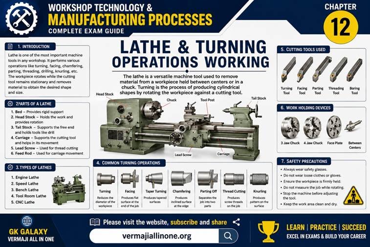
12.1 Definition of Lathe
A lathe is a machine tool in which the workpiece is rotated about its axis while a cutting tool is fed against it to remove material and produce the required shape and dimensions.
Basic Principle
Workpiece → Rotates
Cutting tool → Moves/fed against workpiece
Material → Removed as chips
12.2 Why is Lathe Called the Mother of Machine Tools?
The lathe is called the mother of machine tools because it can perform a large variety of machining operations and has historically played a fundamental role in the development of machine tools.
12.3 Main Functions of a Lathe
A lathe can perform:
- Turning
- Facing
- Taper turning
- Thread cutting
- Knurling
- Drilling
- Boring
- Reaming
- Parting-off
- Grooving
- Chamfering
- Form turning
12.4 Main Parts of a Lathe
The principal parts are:
Bed
Headstock
Tailstock
Carriage
Lead screw
Feed rod
Spindle
Chuck
Tool post
Apron
Cross-slide
Compound rest
12.5 Lathe Bed
The bed is the main supporting structure of the lathe.
It:
Supports the headstock
Supports the tailstock
Supports the carriage
Maintains alignment
Provides guideways for carriage movement
Important
Bed = Foundation/supporting structure of lathe
12.6 Headstock
The headstock is mounted at one end of the lathe bed.
It contains:
Main spindle
Speed-changing mechanism
Gears/pulleys
Bearings
Spindle drive arrangement
Main Function
It provides rotary motion to the workpiece.
12.7 Spindle
The spindle is the rotating shaft of the lathe.
The work-holding device such as a chuck may be mounted on the spindle.
Important
Spindle → Rotates the workpiece
12.8 Tailstock
The tailstock is mounted on the bed opposite the headstock.
It is used for:
Supporting long workpieces
Holding drills
Holding reamers
Holding centres
Supporting work during machining
12.9 Carriage
The carriage carries and moves the cutting tool.
Major parts include:
Saddle
Cross-slide
Compound rest
Tool post
Apron
12.10 Saddle
The saddle is mounted on the lathe bed and supports the cross-slide and other carriage components.
It permits longitudinal movement along the bed.
12.11 Cross-Slide
The cross-slide provides movement of the tool:
Perpendicular to the axis of the workpiece.
It is primarily used for:
Facing
Controlling depth of cut
12.12 Compound Rest
The compound rest is mounted above the cross-slide.
It can be swivelled to set an angle.
It is particularly useful for:
Taper turning
Angular cuts
Short tapers
Fine tool positioning
12.13 Tool Post
The tool post holds the cutting tool.
It allows:
Tool positioning
Tool adjustment
Secure tool clamping
Common types include:
Single tool post
Four-way tool post
uick-change tool post
12.14 Apron
The apron is attached to the front of the carriage.
It contains mechanisms for:
Feed control
Carriage movement
Automatic longitudinal feed
Cross feed
12.15 Lead Screw
The lead screw is used mainly for:
Thread cutting.
It provides controlled movement of the carriage in synchronization with spindle rotation.
Important Exam Point
Lead screw → Thread cutting
12.16 Feed Rod
The feed rod is generally used to transmit power for:
Automatic longitudinal feed
Automatic cross feed
Important
Feed rod → Normal automatic feed
Lead screw → Thread cutting
12.17 Lathe Chuck
A chuck is a work-holding device mounted on the spindle.
Common types:
- Three-jaw chuck
- Four-jaw independent chuck
- Collet chuck
- Magnetic chuck
- Combination chuck
12.18 Three-Jaw Chuck
The three-jaw chuck is also called a:
Self-centering chuck
The three jaws move simultaneously.
Advantages
Quick work holding
Automatic centering
Suitable for circular and hexagonal work
Limitation
It is less suitable when highly accurate independent adjustment of an irregular workpiece is required.
12.19 Four-Jaw Independent Chuck
In a four-jaw independent chuck:
Each jaw can be adjusted independently.
It is suitable for:
Square work
Rectangular work
Irregular work
Accurate setting of eccentric work
12.20 Three-Jaw vs Four-Jaw Chuck
| Three-Jaw | Four-Jaw Independent |
| Self-centering | Independent jaws |
| Quick setting | More time required |
| Circular/hexagonal work | Square/irregular/eccentric work |
| Convenient | Greater setting flexibility |
12.21 Lathe Centres
Centres support the workpiece between headstock and tailstock.
Types include:
Dead centre
Live centre
A centre generally has a standard point angle of approximately:
60°
12.22 Steady Rest
A steady rest provides additional support to a long, slender workpiece.
It is mounted on the:
Lathe bed
It helps reduce:
Deflection
Vibration
Chatter
12.23 Follower Rest
A follower rest is attached to the:
Carriage
It moves with the cutting tool and provides support close to the cutting zone.
12.24 Turning
Turning is the operation of reducing the diameter of a cylindrical workpiece by feeding a cutting tool parallel to the axis of rotation.
Purpose
To produce:
Cylindrical surfaces
Required diameter
Dimensional accuracy
12.25 Facing
Facing is the operation of producing a flat surface at the end of a workpiece by feeding the cutting tool approximately perpendicular to the axis of rotation.
Important
Turning → Tool feed parallel to axis
Facing → Tool feed perpendicular to axis
12.26 Taper Turning
A taper is a gradual reduction or increase in diameter along the length of a cylindrical workpiece.
Taper turning produces:
Conical surfaces.
Methods include:
- Compound rest method
- Tailstock offset method
- Taper turning attachment
- Form tool method
12.27 Thread Cutting
Thread cutting produces:
Helical grooves on a cylindrical or conical surface.
During thread cutting, the tool movement must remain synchronized with spindle rotation.
This is achieved using the:
Lead screw and change gears/gear train as appropriate.
12.28 Knurling
Knurling is a forming operation in which a patterned surface is produced on a workpiece by pressing hardened knurling wheels against it.
Important:
Knurling is not primarily a metal-cutting operation.
It produces:
Diamond pattern
Straight pattern
Improved grip
12.29 Drilling on a Lathe
A drill can be held in the:
Tailstock
The workpiece rotates while the drill is fed into it.
12.30 Boring
Boring is the operation of enlarging or correcting an existing hole using a single-point cutting tool.
Important distinction
Drilling → Produces a hole
Boring → Enlarges/improves an existing hole
12.31 Reaming
Reaming is a finishing operation used to improve the dimensional accuracy and surface finish of an existing hole.
A reamer removes a relatively small amount of material.
12.32 Parting-Off
Parting-off, also called cutting-off, separates a portion of the workpiece from the main stock.
A narrow cutting tool is fed:
Radially toward the centre of the workpiece.
12.33 Grooving
Grooving produces:
A narrow recess or groove on the workpiece.
12.34 Chamfering
Chamfering produces:
A bevelled edge on a workpiece.
It is commonly performed to remove sharp edges.
12.35 Form Turning
In form turning, a specially shaped tool produces:
A predetermined profile in one or a limited number of tool movements.
12.36 Lathe Speed
Spindle speed is normally measured in:
rpm — revolutions per minute
12.37 Cutting Speed in Turning
where:
= cutting speed in m/min
= workpiece diameter in mm
= spindle speed in rpm
Therefore:
12.38 Machining Time in Turning
For simple longitudinal turning:
where:
= machining time in minutes
= length of cut in mm
= feed in mm/rev
= rpm
12.39 Important Lathe Revision Table
| Part | Main Function |
| Bed | Supports machine components |
| Headstock | Drives spindle |
| Spindle | Rotates work |
| Tailstock | Supports work/holds drills |
| Carriage | Supports and moves tool |
| Cross-slide | Cross movement |
| Compound rest | Angular tool movement |
| Tool post | Holds tool |
| Apron | Feed mechanism |
| Lead screw | Thread cutting |
| Feed rod | Automatic feed |
| Chuck | Holds work |
| Steady rest | Supports long work |
| Follower rest | Supports work near cutting zone |
Q1. A lathe is primarily used for:
A. Producing surfaces of revolution
B. Welding plates
C. Casting components
D. Heat treatment
Answer: A. Producing surfaces of revolution
Explanation: The workpiece rotates about its axis while the tool removes material.
Q2. A lathe is commonly called the:
A. Mother of machine tools
B. Father of welding
C. Mother of furnaces
D. King of casting
Answer: A. Mother of machine tools
Explanation: Its versatility and historical importance have led to this traditional designation.
Q3. In a conventional lathe, the workpiece generally:
A. Rotates
B. Remains completely stationary
C. Moves only vertically
D. Reciprocates like a shaper
Answer: A. Rotates
Q4. In turning, the cutting tool generally moves:
A. Parallel to the workpiece axis
B. Only vertically
C. Circumferentially with the work
D. Randomly
Answer: A. Parallel to the workpiece axis
Q5. The main supporting structure of a lathe is the:
A. Bed
B. Chuck
C. Tool post
D. Apron
Answer: A. Bed
Q6. Which lathe component houses the main spindle?
A. Headstock
B. Tailstock
C. Saddle
D. Cross-slide
Answer: A. Headstock
Q7. The spindle of a lathe provides:
A. Rotary motion to the workpiece
B. Cooling water
C. Linear motion to the tailstock only
D. Hydraulic pressure only
Answer: A. Rotary motion to the workpiece
Q8. The tailstock is normally located:
A. Opposite the headstock
B. Inside the chuck
C. Below the bed
D. Inside the apron
Answer: A. Opposite the headstock
Q9. Which part is used to support a long workpiece?
A. Tailstock
B. Tool post
C. Cross-slide
D. Apron
Answer: A. Tailstock
Explanation: A centre mounted in the tailstock can support the free end of a long workpiece.
Q10. Which lathe part carries the cutting tool?
A. Carriage
B. Headstock only
C. Tailstock only
D. Spindle bearing
Answer: A. Carriage
Q11. The tool post is used to:
A. Hold the cutting tool
B. Rotate the workpiece
C. Support the lathe bed
D. Supply coolant only
Answer: A. Hold the cutting tool
Q12. The cross-slide provides tool movement:
A. Perpendicular to the workpiece axis
B. Only parallel to the axis
C. Circularly around the spindle
D. Vertically only
Answer: A. Perpendicular to the workpiece axis
Q13. The compound rest is especially useful for:
A. Taper turning
B. Cooling
C. Workpiece casting
D. Welding
Answer: A. Taper turning
Q14. The apron contains mechanisms associated with:
A. Carriage feed
B. Workpiece melting
C. Grinding-wheel balancing
D. Casting
Answer: A. Carriage feed
Q15. The lead screw is mainly used for:
A. Thread cutting
B. Cooling
C. Workpiece heating
D. Grinding
Answer: A. Thread cutting
Q16. The feed rod is mainly used for:
A. Powering normal automatic feeds
B. Holding the workpiece
C. Cutting threads only
D. Supporting the bed
Answer: A. Powering normal automatic feeds
Q17. A three-jaw chuck is generally:
A. Self-centering
B. Independent-jaw only
C. Used only for square work
D. Used only for grinding
Answer: A. Self-centering
Q18. In a four-jaw independent chuck:
A. Each jaw can be adjusted independently
B. All jaws always move simultaneously
C. There are no jaws
D. The chuck cannot hold irregular work
Answer: A. Each jaw can be adjusted independently
Q19. A three-jaw chuck is particularly suitable for:
A. Circular work
B. Highly irregular work only
C. Square work only
D. Eccentric work requiring independent adjustment
Answer: A. Circular work
Q20. Which chuck is particularly suitable for irregular or eccentric work?
A. Four-jaw independent chuck
B. Three-jaw self-centering chuck only
C. Collet only
D. Magnetic chuck only
Answer: A. Four-jaw independent chuck
Q21. Facing produces:
A. A flat end surface
B. A helical thread
C. A knurled surface only
D. A deep hole only
Answer: A. A flat end surface
Q22. In facing, the tool generally moves:
A. Radially across the end face
B. Only parallel to the work axis
C. Around the spindle without feed
D. Along the tailstock quill only
Answer: A. Radially across the end face
Q23. Boring is used to:
A. Enlarge an existing hole
B. Produce a hole from solid material only
C. Produce external threads only
D. Produce knurling
Answer: A. Enlarge an existing hole
Q24. Knurling is primarily:
A. A forming operation
B. A drilling operation
C. A grinding operation
D. A welding operation
Answer: A. A forming operation
Explanation: Knurling forms a patterned surface by pressing hardened rollers against the workpiece.
Q25. Parting-off is used to:
A. Separate a portion of the workpiece
B. Produce a taper only
C. Produce a thread only
D. Increase workpiece diameter
Answer: A. Separate a portion of the workpiece
A. TYPES OF LATHES — MCQs 26–40
Q26. Which lathe is most commonly used for general-purpose machining?
A. Centre lathe
B. Special-purpose lathe
C. Automatic screw machine only
D. Wheel lathe
Answer: A. Centre lathe
Explanation: A centre lathe is a versatile machine suitable for a wide range of general machining operations.
Q27. A centre lathe is also commonly known as:
A. Engine lathe
B. Turret lathe only
C. Automatic lathe
D. Vertical boring machine
Answer: A. Engine lathe
Explanation: The conventional centre lathe is commonly referred to as an engine lathe.
Q28. Which lathe is particularly suitable for repetitive production work?
A. Capstan and turret lathe
B. Centre lathe only
C. Bench vice
D. Surface plate
Answer: A. Capstan and turret lathe
Explanation: Capstan and turret lathes are designed for repetitive machining operations and multiple-tool setups.
Q29. In a turret lathe, the turret generally carries:
A. Multiple tools
B. Only one centre
C. Coolant only
D. Workpiece only
Answer: A. Multiple tools
Explanation: Multiple tools can be mounted on the turret for sequential machining operations.
Q30. A major advantage of a turret lathe is:
A. Reduced tool-changing time
B. No cutting tool required
C. No spindle rotation
D. No work-holding device
Answer: A. Reduced tool-changing time
Explanation: Multiple tools are preset on the turret and brought into operation as required.
Q31. An automatic lathe is designed primarily for:
A. Automatic/repetitive production
B. Manual filing
C. Heat treatment
D. Casting
Answer: A. Automatic/repetitive production
Q32. A special-purpose lathe is designed for:
A. Specific machining applications
B. Every possible manufacturing operation
C. Welding only
D. Forging only
Answer: A. Specific machining applications
Q33. A vertical lathe is especially useful for:
A. Large-diameter, heavy workpieces
B. Very small drills only
C. Hand filing
D. Sheet-metal cutting only
Answer: A. Large-diameter, heavy workpieces
Explanation: Vertical orientation can make loading and supporting large heavy components easier.
Q34. In a vertical turning machine, the workpiece spindle axis is generally:
A. Vertical
B. Horizontal
C. Inclined at 45° always
D. Random
Answer: A. Vertical
Q35. A tool room lathe is primarily associated with:
A. Precision and tool-room work
B. Mass casting
C. Welding pipelines
D. Heat treatment
Answer: A. Precision and tool-room work
Q36. A bench lathe is generally:
A. Small and mounted on a bench
B. Designed only for very large castings
C. Used only for forging
D. A vertical boring machine
Answer: A. Small and mounted on a bench
Q37. A CNC lathe is controlled by:
A. Computer numerical control
B. Manual handwheel only
C. Gravity
D. Steam pressure
Answer: A. Computer numerical control
Q38. CNC lathes generally provide:
A. High repeatability and automated control
B. No dimensional control
C. Only manual tool movement
D. No programming capability
Answer: A. High repeatability and automated control
Q39. A turret lathe is particularly useful when:
A. Several operations must be performed sequentially
B. Only one manual cut is required
C. No tooling is available
D. The workpiece cannot rotate
Answer: A. Several operations must be performed sequentially
Q40. Which machine is best suited to high-volume repetitive production with automatic operation?
A. Automatic lathe
B. Bench vice
C. Hand drill
D. Surface plate
Answer: A. Automatic lathe
B. WORK-HOLDING DEVICES — MCQs 41–55
Q41. A chuck is used primarily to:
A. Hold the workpiece
B. Hold cutting fluid
C. Support the machine bed
D. Measure diameter
Answer: A. Hold the workpiece
Q42. A collet chuck is particularly suitable for:
A. Small-diameter work requiring accurate holding
B. Very large castings only
C. Welding plates
D. Sand moulds
Answer: A. Small-diameter work requiring accurate holding
Q43. A faceplate is commonly used for:
A. Irregularly shaped work
B. Only small drills
C. Thread measurement
D. Grinding wheels
Answer: A. Irregularly shaped work
Explanation: Work that cannot conveniently be held in a conventional chuck can be secured to a faceplate using suitable clamps.
Q44. Work held between centres is supported by:
A. Headstock and tailstock centres
B. Two chucks only
C. Two tool posts
D. Two aprons
Answer: A. Headstock and tailstock centres
Q45. A lathe dog is used when work is:
A. Held between centres
B. Held only in a three-jaw chuck
C. Being drilled on a radial drill
D. Being cast
Answer: A. Held between centres
Explanation: A lathe dog transmits rotary motion from the driving plate/faceplate to the workpiece.
Q46. A driving plate is associated with:
A. Work held between centres
B. Milling cutters only
C. Grinding wheels only
D. Welding machines
Answer: A. Work held between centres
Q47. A steady rest is used to:
A. Support long slender work
B. Hold the cutting tool
C. Drive the spindle
D. Cut threads
Answer: A. Support long slender work
Q48. A steady rest is normally mounted on the:
A. Lathe bed
B. Tool post
C. Chuck jaws
D. Tailstock quill only
Answer: A. Lathe bed
Q49. A follower rest generally moves with:
A. The carriage
B. The headstock
C. The machine bed
D. The spindle only
Answer: A. The carriage
Q50. A follower rest supports the work:
A. Close to the cutting tool
B. Only at the tailstock
C. Inside the headstock
D. At the chuck jaws only
Answer: A. Close to the cutting tool
Q51. The primary purpose of a centre is to:
A. Support the workpiece
B. Cut threads
C. Increase spindle speed
D. Measure surface roughness
Answer: A. Support the workpiece
Q52. A live centre generally:
A. Rotates with the work
B. Always remains stationary relative to the work
C. Is used only for grinding
D. Is a cutting tool
Answer: A. Rotates with the work
Q53. A dead centre generally:
A. Does not rotate with the work
B. Rotates at spindle speed
C. Cuts the workpiece
D. Drives the spindle
Answer: A. Does not rotate with the work
Explanation: A traditional dead centre remains stationary relative to the machine while the work rotates around it; lubrication may be required at the contact.
Q54. The standard included angle of a conventional lathe centre is approximately:
A. 30°
B. 45°
C. 60°
D. 90°
Answer: C. 60°
Q55. A four-jaw independent chuck is advantageous for:
A. Eccentric work
B. Only automatic centering
C. Only circular bar stock
D. Grinding operations only
Answer: A. Eccentric work
Explanation: Independent jaw adjustment allows the work axis to be deliberately offset.
C. TURNING OPERATIONS — MCQs 56–70
Q56. Turning is used primarily to produce:
A. Cylindrical surfaces
B. Flat plates only
C. Gear teeth only
D. Welding joints
Answer: A. Cylindrical surfaces
Q57. Straight turning generally involves tool movement:
A. Parallel to the work axis
B. Perpendicular to the work axis only
C. Radially inward only
D. Vertically upward only
Answer: A. Parallel to the work axis
Q58. Facing is performed to produce:
A. A flat end surface
B. A helical groove
C. A knurled pattern only
D. An internal thread only
Answer: A. A flat end surface
Q59. In facing, the cutting tool generally moves:
A. Across the end face toward or away from the axis
B. Only parallel to the work axis
C. Around the work without contact
D. Along the lead screw only
Answer: A. Across the end face toward or away from the axis
Q60. Taper turning produces:
A. Conical surfaces
B. Flat surfaces only
C. Spherical surfaces only
D. Gear teeth
Answer: A. Conical surfaces
Q61. Which is NOT a common method of taper turning?
A. Compound rest method
B. Tailstock offset method
C. Taper attachment
D. Sand casting method
Answer: D. Sand casting method
Q62. The compound-rest method is particularly suitable for:
A. Short tapers
B. Extremely long shafts only
C. Large castings only
D. Welding
Answer: A. Short tapers
Q63. Tailstock offset is generally suitable for:
A. Long, slight tapers
B. Very short steep tapers only
C. Thread cutting only
D. Knurling only
Answer: A. Long, slight tapers
Q64. Taper turning attachment is useful for:
A. Accurate taper production
B. Increasing workpiece hardness
C. Casting
D. Welding
Answer: A. Accurate taper production
Q65. Thread cutting on a lathe produces:
A. Helical grooves
B. Flat surfaces only
C. Random grooves
D. Knurled surfaces only
Answer: A. Helical grooves
Q66. During thread cutting, the carriage must move:
A. In synchronism with spindle rotation
B. Independently of spindle rotation
C. Only manually without synchronization
D. Randomly
Answer: A. In synchronism with spindle rotation
Q67. The lead screw is especially important during:
A. Thread cutting
B. Simple grinding
C. Casting
D. Heat treatment
Answer: A. Thread cutting
Q68. Parting-off is performed using:
A. A narrow parting tool
B. A drill
C. A reamer
D. A milling cutter
Answer: A. A narrow parting tool
Q69. In parting-off, the tool is fed:
A. Radially toward the work axis
B. Parallel to the axis only
C. Tangentially without penetration
D. Vertically upward only
Answer: A. Radially toward the work axis
Q70. Grooving produces:
A. A narrow recess
B. A complete hole
C. A taper only
D. A flat end only
Answer: A. A narrow recess
D. DRILLING, BORING, REAMING & KNURLING — MCQs 71–82
Q71. Drilling on a lathe is generally performed by mounting the drill in the:
A. Tailstock
B. Tool post only
C. Apron
D. Bed
Answer: A. Tailstock
Q72. In drilling on a conventional lathe:
A. Workpiece rotates and drill is fed
B. Drill rotates while workpiece always remains stationary
C. Neither rotates
D. Only the tailstock rotates
Answer: A. Workpiece rotates and drill is fed
Q73. Boring is used to:
A. Enlarge an existing hole
B. Produce an external thread only
C. Produce a flat end only
D. Produce a knurled surface
Answer: A. Enlarge an existing hole
Q74. A boring tool is generally:
A. Single-point cutting tool
B. Multi-point milling cutter
C. Grinding wheel
D. Welding electrode
Answer: A. Single-point cutting tool
Q75. Reaming is primarily a:
A. Finishing operation for holes
B. Rough forging operation
C. Welding operation
D. Casting operation
Answer: A. Finishing operation for holes
Q76. Compared with drilling, reaming generally removes:
A. A small amount of material
B. The entire workpiece
C. No material under any condition
D. A very large amount of material
Answer: A. A small amount of material
Q77. Knurling produces:
A. A patterned surface
B. A drilled hole
C. A conical hole only
D. A flat end face
Answer: A. A patterned surface
Q78. Knurling is primarily a:
A. Metal-forming operation
B. Cutting-only operation
C. Welding operation
D. Heat-treatment operation
Answer: A. Metal-forming operation
Q79. Knurling is commonly used to:
A. Improve grip
B. Produce deep holes
C. Cut threads
D. Reduce length
Answer: A. Improve grip
Q80. A common knurl pattern is:
A. Diamond
B. Square hole
C. Spiral drill
D. Hexagonal bore
Answer: A. Diamond
Q81. Chamfering is performed to:
A. Produce a bevelled edge
B. Produce a deep hole
C. Increase diameter uniformly
D. Produce a casting cavity
Answer: A. Produce a bevelled edge
Q82. Form turning is used to:
A. Produce a predetermined profile
B. Produce only flat surfaces
C. Drill holes only
D. Cut gears only
Answer: A. Produce a predetermined profile
E. LATHE CALCULATIONS — MCQs 83–100
Q83. The turning cutting-speed equation is:
A.
B.
C.
D.
Answer: A.
Q84. A 50 mm diameter workpiece rotates at 1000 rpm. The cutting speed is approximately:
A. 78.5 m/min
B. 157 m/min
C. 314 m/min
D. 500 m/min
Answer: B. 157 m/min
Q85. If cutting speed is 100 m/min and workpiece diameter is 50 mm, spindle speed is approximately:
A. 318 rpm
B. 637 rpm
C. 1000 rpm
D. 2000 rpm
Answer: B. 637 rpm
Q86. A workpiece diameter is reduced from 80 mm to 70 mm. Depth of cut is:
A. 2.5 mm
B. 5 mm
C. 10 mm
D. 15 mm
Answer: B. 5 mm
Q87. If feed is 0.25 mm/rev and spindle speed is 800 rpm, feed rate is:
A. 100 mm/min
B. 150 mm/min
C. 200 mm/min
D. 320 mm/min
Answer: C. 200 mm/min
Q88. If the length of cut is 100 mm, feed is 0.2 mm/rev and spindle speed is 500 rpm, machining time is:
A. 0.5 min
B. 1 min
C. 2 min
D. 5 min
Answer: B. 1 min
Q89. If feed is doubled while speed remains constant, machining time for the same length generally:
A. Decreases
B. Doubles
C. Remains unchanged
D. Becomes infinite
Answer: A. Decreases
Explanation: Higher feed means greater tool travel per revolution.
Q90. If spindle speed doubles and feed remains constant, feed rate:
A. Doubles
B. Halves
C. Remains constant
D. Becomes zero
Answer: A. Doubles
Q91. The pitch of a single-start thread is equal to its:
A. Lead
B. Diameter
C. Radius
D. Depth of cut
Answer: A. Lead
Explanation: For a single-start thread:
Q92. For a double-start thread:
A. Lead = 2 × pitch
B. Lead = pitch/2
C. Lead = pitch
D. Lead = 0
Answer: A. Lead = 2 × pitch
Q93. For a three-start thread, the relationship is:
A. Lead = 3 × pitch
B. Lead = pitch/3
C. Lead = pitch
D. Lead = 2 × pitch
Answer: A. Lead = 3 × pitch
Q94. If a single-start thread has a pitch of 2 mm, its lead is:
A. 1 mm
B. 2 mm
C. 4 mm
D. 6 mm
Answer: B. 2 mm
Q95. If a double-start thread has a pitch of 2 mm, its lead is:
A. 1 mm
B. 2 mm
C. 4 mm
D. 6 mm
Answer: C. 4 mm
Q96. During thread cutting, if the required thread pitch is , the carriage must advance:
A. mm per spindle revolution for a single-start thread
B. mm for every single-start thread
C. Zero mm per revolution
D. Randomly
Answer: A. mm per spindle revolution for a single-start thread
Q97. A workpiece rotates at 500 rpm and the feed is 0.4 mm/rev. The feed rate is:
A. 100 mm/min
B. 200 mm/min
C. 400 mm/min
D. 900 mm/min
Answer: B. 200 mm/min
Q98. A workpiece of diameter 100 mm rotates at 318 rpm. Cutting speed is approximately:
A. 50 m/min
B. 100 m/min
C. 150 m/min
D. 318 m/min
Answer: B. 100 m/min
Q99. If a workpiece of initial diameter 60 mm is reduced to 52 mm in one turning pass, depth of cut is:
A. 2 mm
B. 4 mm
C. 8 mm
D. 10 mm
Answer: B. 4 mm
Q100. Which combination is correct?
A. Lead screw — thread cutting
B. Cross-slide — spindle rotation
C. Chuck — coolant storage
D. Tailstock — cutting speed measurement
Answer: A. Lead screw — thread cutting
Explanation: The lead screw synchronizes carriage movement with spindle rotation during thread cutting.
CHAPTER 12 — IMPORTANT EXAM REVISION
Remember these pairs:
Bed → Supports machine
Headstock → Drives spindle
Spindle → Rotates work
Tailstock → Supports work / holds drill
Carriage → Carries cutting tool
Cross-slide → Cross movement
Compound rest → Taper turning
Tool post → Holds tool
Apron → Feed mechanism
Lead screw → Thread cutting
Feed rod → Automatic feed
3-jaw chuck → Self-centering
4-jaw independent chuck → Eccentric/irregular work
Steady rest → Fixed support on bed
Follower rest → Moves with carriage
Turning → Cylindrical surface
Facing → Flat end surface
Taper turning → Conical surface
Boring → Enlarges existing hole
Reaming → Finishes existing hole
Knurling → Pattern/grip
Parting-off → Separates work
Grooving → Narrow recess
Chamfering → Bevelled edge
Single-start thread → Lead = pitch
Double-start thread → Lead = 2 × pitch
CHAPTER 13 — DRILLING MACHINES & DRILLING OPERATIONS
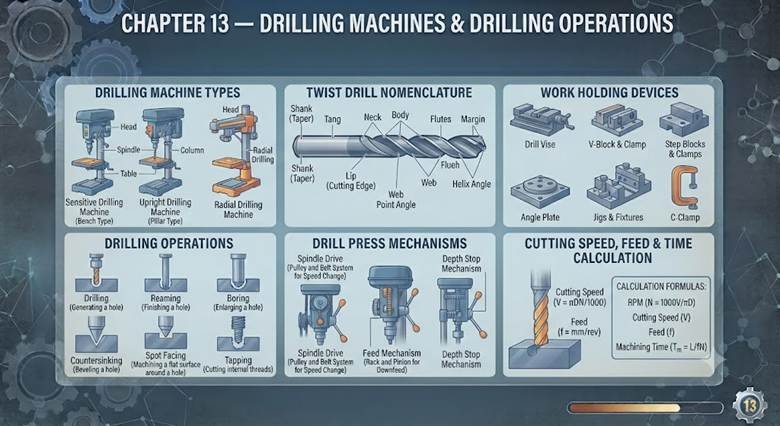
13.1 Definition of Drilling
Drilling is a machining operation used to produce a circular hole in a solid material by means of a rotating multi-point cutting tool called a drill.
The most commonly used drill is the:
Twist Drill
13.2 Principle of Drilling
In conventional drilling:
The drill rotates.
The drill is fed axially into the workpiece.
Cutting edges remove material.
Material is removed in the form of chips.
Basic principle:
Rotating drill + axial feed → Hole formation
13.3 Main Characteristics of Drilling
Drilling is generally:
A hole-making operation
A multi-point cutting operation
A rotary cutting operation
Usually performed with a twist drill
13.4 What is a Twist Drill?
A twist drill is a multi-point cutting tool having helical flutes that provide cutting edges and passages for chip removal.
It generally consists of:
- Shank
- Body
- Flutes
- Lands
- Margins
- Web
- Point
- Cutting lips
13.5 Main Parts of a Twist Drill
1. Shank
The shank is the portion by which the drill is held in the machine.
Two common types are:
Straight shank
Taper shank
2. Body
The body is the portion between the shank and the point.
It contains:
Flutes
Lands
Margins
Web
3. Flutes
Flutes are helical grooves running along the body of the drill.
Functions of flutes:
Provide chip space
Help remove chips
Allow cutting fluid to reach the cutting zone
Form the cutting edges
4. Lands
The raised portions between adjacent flutes are called:
Lands
5. Margin
The narrow raised portion along the leading edge of the land is called the:
Margin
The margin helps guide the drill inside the hole.
6. Web
The central portion of the drill between the flutes is called the:
Web
The web provides strength to the drill.
7. Point
The conical cutting portion at the end of the drill is called the:
Point
8. Cutting Lips
The two principal cutting edges of a conventional twist drill are called:
Cutting lips
13.6 Standard Twist Drill
A standard twist drill commonly has:
Two main cutting lips
Two flutes
A chisel edge
A point angle of approximately 118°
Important Exam Fact
Standard drill point angle ≈ 118°
13.7 Chisel Edge
The chisel edge is located at the centre of the drill point.
It does not cut in the same efficient shearing manner as the main cutting lips.
It tends to:
Extrude material
Increase thrust force
Require substantial axial force
13.8 Drill Point Angle
The included angle between the two cutting lips is called the:
Point angle
For a conventional general-purpose twist drill:
is a commonly used value.
13.9 Helix Angle
The angle made by the helical flute with the drill axis is called the:
Helix angle
A commonly used standard twist drill has a helix angle of approximately:
13.10 Rake Angle of Drill
The rake angle in a twist drill varies along the cutting edge.
It is generally:
Smaller near the centre
Larger toward the outer circumference
13.11 Clearance Angle
The clearance angle prevents excessive rubbing between the drill and the newly machined hole surface.
If clearance is insufficient:
Friction increases
Heat increases
Tool wear increases
13.12 Drill Materials
Common drill materials include:
Carbon Tool Steel
Used for relatively low-speed applications.
High-Speed Steel — HSS
Widely used because of:
Good hardness
Good toughness
Good hot hardness
Good wear resistance
Carbide
Used where:
High cutting speed is required
High productivity is required
Suitable machine rigidity is available
13.13 Types of Drilling Machines
Important types include:
- Portable drilling machine
- Sensitive drilling machine
- Bench drilling machine
- Pillar drilling machine
- Upright drilling machine
- Radial drilling machine
- Gang drilling machine
- Multi-spindle drilling machine
- Automatic drilling machine
- CNC drilling machine
13.14 Portable Drilling Machine
A portable drilling machine is:
Small
Easily movable
Suitable for drilling holes at different locations
It is useful where moving the workpiece to a stationary drilling machine is difficult.
13.15 Sensitive Drilling Machine
A sensitive drilling machine is designed for:
Small holes
Light drilling
Accurate control of feed by the operator
The operator can sense the cutting pressure through the hand feed mechanism.
13.16 Bench Drilling Machine
A bench drilling machine is mounted on a:
Bench or table
It is commonly used for:
Small workpieces
Small and medium-sized holes
Light-duty drilling
13.17 Pillar Drilling Machine
A pillar drilling machine has a vertical supporting column or pillar.
It is suitable for:
General-purpose drilling
Larger workpieces than typical bench drills
13.18 Upright Drilling Machine
An upright drilling machine is a relatively heavy stationary drilling machine used for:
Medium and large work
Larger hole sizes
Production applications
13.19 Radial Drilling Machine
A radial drilling machine has a:
Radial arm
The drill head can move along the radial arm.
Major advantage
It can drill holes at different positions without repeatedly moving a large workpiece.
It is particularly useful for:
Large and heavy workpieces.
13.20 Gang Drilling Machine
A gang drilling machine has several drilling heads arranged in a row.
Different operations can be performed sequentially, such as:
Drilling
Counterboring
Reaming
Tapping
This reduces handling time.
13.21 Multi-Spindle Drilling Machine
A multi-spindle machine has:
Several spindles
It is useful when:
Multiple holes must be produced
High production rate is required
13.22 Main Parts of a Drilling Machine
Typical parts include:
Base
Column
Table
Spindle
Drill head
Motor
Feed mechanism
Chuck
Quill
Belt/gear drive
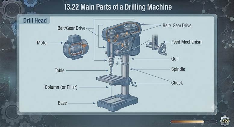
13.23 Base
The base:
Supports the machine
Provides stability
May support the column
May accommodate large workpieces
13.24 Column
The column is the vertical supporting member.
It supports:
Drill head
Table
Other machine components
13.25 Table
The table supports the workpiece.
It may be:
Fixed
Adjustable vertically
Swivelled depending on machine design
13.26 Spindle
The spindle:
Rotates the drill
Transmits power to the drill
13.27 Drill Chuck
A drill chuck is used to hold drills having suitable shanks.
13.28 Quill
The quill carries the spindle assembly and permits axial movement of the drill in many drilling machines.
13.29 Drilling Operations
Drilling-related operations include:
- Drilling
- Reaming
- Boring
- Counterboring
- Countersinking
- Spot facing
- Tapping
- Trepanning
13.30 Reaming
Reaming is a finishing operation used to improve the size accuracy and surface finish of an existing hole.
A reamer removes a relatively small amount of material.
Remember:
Drilling → Makes hole
Reaming → Finishes hole
13.31 Boring
Boring is the process of enlarging an existing hole using a cutting tool.
It can also improve:
Hole accuracy
Alignment
Surface finish
13.32 Counterboring
Counterboring produces:
A cylindrical enlargement at the mouth of an existing hole.
It is commonly used to provide seating for:
Socket-head screws
Bolt heads
Similar fasteners
13.33 Countersinking
Countersinking produces:
A conical enlargement at the mouth of a hole.
It is used to accommodate:
Countersunk screw heads.
13.34 Spot Facing
Spot facing produces:
A flat circular seating surface around an existing hole.
It is often used where a bolt head or nut requires a flat bearing surface.
13.35 Tapping
Tapping is the operation of producing:
Internal threads inside a hole.
The tool used is called a:
Tap
13.36 Die
A die is generally used to produce:
External threads
Therefore:
Tap → Internal thread
Die → External thread
13.37 Trepanning
Trepanning produces a:
Large-diameter hole by removing material in the form of a ring rather than removing the complete circular core.
It can save material compared with conventional solid drilling for large holes.
13.38 Drilling Cutting Speed
The cutting speed of a drill is:
where:
= cutting speed in m/min
= drill diameter in mm
= spindle speed in rpm
Therefore:
13.39 Feed in Drilling
Feed is commonly expressed as:
mm/rev
Feed rate:
where:
= feed in mm/rev
= rpm
= feed rate in mm/min
13.40 Drilling Time
For simple drilling, machining time can be approximated by:
where is the effective drilling length.
In practical calculations, approach and breakthrough allowances may need to be included depending on the question.
13.41 Important Drilling Revision Table
| Item | Key Fact |
| Drilling | Produces a hole |
| Drill | Multi-point cutting tool |
| Twist drill | Most common drill |
| Standard point angle | About 118° |
| Flute | Chip removal |
| Web | Provides drill strength |
| Margin | Guides drill |
| Chisel edge | At centre of point |
| HSS | Common drill material |
| Radial drill | Large/heavy work |
| Gang drill | Sequential operations |
| Reaming | Hole finishing |
| Boring | Enlarges existing hole |
| Counterboring | Cylindrical enlargement |
| Countersinking | Conical enlargement |
| Spot facing | Flat seating surface |
| Tapping | Internal thread |
| Die | External thread |
| Trepanning | Large hole with annular cutting |
Q1. Drilling is primarily used to:
A. Produce holes
B. Produce external threads only
C. Produce flat surfaces only
D. Produce gear teeth
Answer: A. Produce holes
Explanation: Drilling is fundamentally a hole-making machining operation.
Q2. A twist drill is a:
A. Multi-point cutting tool
B. Single-point tool
C. Grinding wheel
D. Forming die
Answer: A. Multi-point cutting tool
Q3. In conventional drilling, the drill generally:
A. Rotates and is fed axially
B. Only moves laterally
C. Remains completely stationary
D. Reciprocates without rotation
Answer: A. Rotates and is fed axially
Q4. The most commonly used drill for general-purpose drilling is:
A. Twist drill
B. Slab cutter
C. Form cutter
D. Side cutter
Answer: A. Twist drill
Q5. The helical grooves on a twist drill are called:
A. Flutes
B. Lands
C. Margins
D. Webs
Answer: A. Flutes
Q6. One important function of drill flutes is:
A. Chip removal
B. Workpiece heating
C. Increasing workpiece diameter
D. Holding the machine table
Answer: A. Chip removal
Q7. The central portion of a twist drill between the flutes is called:
A. Web
B. Margin
C. Shank
D. Land
Answer: A. Web
Q8. The web primarily provides:
A. Strength to the drill
B. Coolant storage
C. Workpiece rotation
D. Machine-bed support
Answer: A. Strength to the drill
Q9. The narrow raised portion that helps guide the drill in the hole is called:
A. Margin
B. Web
C. Point
D. Shank
Answer: A. Margin
Q10. The standard point angle of a general-purpose twist drill is approximately:
A. 60°
B. 90°
C. 118°
D. 180°
Answer: C. 118°
Q11. The chisel edge of a twist drill is located:
A. At the centre of the drill point
B. At the shank end
C. On the outer margin only
D. Inside the machine spindle
Answer: A. At the centre of the drill point
Q12. The chisel edge mainly contributes to:
A. Thrust force
B. Spindle lubrication
C. Machine cooling
D. Workpiece rotation
Answer: A. Thrust force
Explanation: The chisel edge does not cut efficiently by pure shearing and therefore requires significant axial force.
Q13. A common material for twist drills is:
A. High-speed steel
B. Rubber
C. Wood
D. Mild plastic
Answer: A. High-speed steel
Q14. HSS stands for:
A. High-Speed Steel
B. High-Surface Steel
C. Heat-Sensitive Steel
D. Hard-Shaped Steel
Answer: A. High-Speed Steel
Q15. A portable drilling machine is useful because:
A. It can be moved to the work
B. It can only machine stationary work
C. It cannot rotate a drill
D. It is used only for grinding
Answer: A. It can be moved to the work
Q16. A sensitive drilling machine is particularly suitable for:
A. Small holes and light work
B. Huge castings only
C. Heavy forging only
D. Large-diameter boring only
Answer: A. Small holes and light work
Q17. A bench drilling machine is generally mounted on a:
A. Bench or table
B. Crane
C. Furnace
D. Lathe spindle
Answer: A. Bench or table
Q18. A radial drilling machine is particularly suitable for:
A. Large and heavy workpieces
B. Only tiny watch components
C. Hand filing
D. Heat treatment
Answer: A. Large and heavy workpieces
Q19. The main special feature of a radial drilling machine is its:
A. Radial arm
B. Lathe chuck
C. Grinding wheel
D. Tailstock
Answer: A. Radial arm
Q20. A gang drilling machine contains:
A. Several drilling units arranged together
B. Only one hand drill
C. No spindle
D. Only a grinding wheel
Answer: A. Several drilling units arranged together
Q21. Reaming is primarily used to:
A. Finish an existing hole
B. Produce a rough hole from solid material
C. Cut external threads
D. Produce a knurled surface
Answer: A. Finish an existing hole
Q22. Boring is primarily used to:
A. Enlarge an existing hole
B. Produce external threads
C. Produce a flat face only
D. Produce a knurled pattern
Answer: A. Enlarge an existing hole
Q23. Tapping is used to produce:
A. Internal threads
B. External threads
C. Flat surfaces
D. Conical external surfaces only
Answer: A. Internal threads
Q24. Countersinking produces:
A. A conical enlargement at the mouth of a hole
B. A cylindrical enlargement only
C. A flat circular seating surface only
D. An external thread
Answer: A. A conical enlargement at the mouth of a hole
Q25. Counterboring produces:
A. A cylindrical enlargement at the mouth of a hole
B. A conical enlargement
C. An external thread
D. A knurled surface
Answer: A. A cylindrical enlargement at the mouth of a hole
A. TWIST DRILL GEOMETRY — MCQs 26–40
Q26. The angle included between the two main cutting lips of a standard twist drill is approximately:
A. 60°
B. 90°
C. 118°
D. 180°
Answer: C. 118°
Explanation: A standard general-purpose twist drill commonly uses a point angle of approximately 118°.
Q27. The angle of a twist-drill helix is measured between the:
A. Helix and drill axis
B. Cutting edge and work surface
C. Drill point and shank
D. Web and margin
Answer: A. Helix and drill axis
Q28. The main cutting edges of a twist drill are called:
A. Cutting lips
B. Margins
C. Lands
D. Webs
Answer: A. Cutting lips
Q29. The flutes of a twist drill are primarily provided for:
A. Chip removal
B. Increasing drill diameter
C. Holding the workpiece
D. Measuring hole depth
Answer: A. Chip removal
Q30. The land of a twist drill is:
A. The portion between adjacent flutes
B. The central web
C. The shank
D. The cutting point only
Answer: A. The portion between adjacent flutes
Q31. The margin of a twist drill helps to:
A. Guide the drill in the hole
B. Drive the spindle
C. Hold the workpiece
D. Measure cutting speed
Answer: A. Guide the drill in the hole
Q32. The web of a twist drill is generally:
A. Thicker toward the shank
B. Completely absent
C. Used as a cutting insert
D. A coolant passage only
Answer: A. Thicker toward the shank
Explanation: The web provides strength and its thickness commonly increases toward the shank.
Q33. The shank of a drill is used to:
A. Hold the drill in the machine
B. Remove chips
C. Cut the workpiece directly
D. Guide the drill inside the hole
Answer: A. Hold the drill in the machine
Q34. A straight-shank drill is commonly held by:
A. Drill chuck
B. Faceplate
C. Lathe dog
D. Steady rest
Answer: A. Drill chuck
Q35. A taper-shank drill is commonly mounted directly in:
A. A suitable tapered spindle/socket
B. A three-jaw lathe chuck only
C. A milling vice only
D. A faceplate
Answer: A. A suitable tapered spindle/socket
Q36. The point angle of a drill affects:
A. Cutting performance and thrust
B. Machine colour
C. Workpiece weight only
D. Coolant capacity
Answer: A. Cutting performance and thrust
Q37. A smaller point angle generally produces:
A. A sharper included point
B. A completely flat drill point
C. No cutting edge
D. Zero rake
Answer: A. A sharper included point
Q38. The clearance angle in drilling is provided mainly to:
A. Prevent rubbing behind the cutting edge
B. Increase friction
C. Stop chip formation
D. Increase drill weight
Answer: A. Prevent rubbing behind the cutting edge
Q39. Insufficient drill clearance can result in:
A. Increased rubbing and heat
B. Zero friction
C. Infinite tool life
D. No thrust force
Answer: A. Increased rubbing and heat
Q40. The drill point is the:
A. Cutting portion at the end of the drill
B. Holding portion at the shank
C. Machine spindle
D. Drill chuck
Answer: A. Cutting portion at the end of the drill
B. DRILLING MACHINE PARTS — MCQs 41–50
Q41. The base of a drilling machine primarily provides:
A. Support and stability
B. Cutting action
C. Thread cutting
D. Chip formation
Answer: A. Support and stability
Q42. The vertical structural member of many drilling machines is the:
A. Column
B. Chuck
C. Spindle
D. Quill only
Answer: A. Column
Q43. The drilling-machine table is used primarily to:
A. Support the workpiece
B. Rotate the drill
C. Store chips
D. Drive the motor
Answer: A. Support the workpiece
Q44. The spindle of a drilling machine:
A. Rotates the drill
B. Supports the floor
C. Holds coolant only
D. Measures hole diameter
Answer: A. Rotates the drill
Q45. The drill head generally contains:
A. Spindle and drive mechanism
B. Only the workpiece
C. Only the machine table
D. Only the coolant tank
Answer: A. Spindle and drive mechanism
Q46. The quill provides:
A. Axial movement of the spindle/drill assembly
B. Horizontal workpiece rotation
C. Coolant filtration only
D. Table lubrication only
Answer: A. Axial movement of the spindle/drill assembly
Q47. A drill chuck is used to:
A. Hold the drill
B. Hold the machine table
C. Support the column
D. Measure drill angle
Answer: A. Hold the drill
Q48. The feed mechanism of a drilling machine controls:
A. Axial movement of the drill
B. Workpiece colour
C. Coolant composition
D. Machine foundation
Answer: A. Axial movement of the drill
Q49. The motor of a drilling machine provides:
A. Power for spindle rotation
B. Workpiece measurement
C. Cutting-fluid filtration only
D. Manual feed only
Answer: A. Power for spindle rotation
Q50. The machine table may be adjustable to:
A. Position the workpiece correctly
B. Increase drill hardness
C. Change workpiece material
D. Remove the spindle
Answer: A. Position the workpiece correctly
C. DRILLING MACHINE TYPES — MCQs 51–60
Q51. Which drilling machine is suitable for large and heavy workpieces?
A. Radial drilling machine
B. Sensitive drilling machine
C. Small bench drill only
D. Hand drill only
Answer: A. Radial drilling machine
Q52. A sensitive drilling machine is mainly intended for:
A. Small holes and light work
B. Very large holes in heavy castings
C. Large gear cutting
D. Heavy forging
Answer: A. Small holes and light work
Q53. A gang drilling machine is useful because:
A. Several operations can be performed sequentially
B. It has no drill
C. It cannot perform production work
D. It eliminates all cutting tools
Answer: A. Several operations can be performed sequentially
Q54. A multi-spindle drilling machine is particularly useful for:
A. Producing multiple holes efficiently
B. Single manual filing
C. Heat treatment
D. Welding
Answer: A. Producing multiple holes efficiently
Q55. A portable drilling machine is especially useful when:
A. The machine must be taken to the work
B. The workpiece is too small for any machine
C. Only grinding is required
D. No hole is required
Answer: A. The machine must be taken to the work
Q56. An upright drilling machine is generally used for:
A. Medium and heavy drilling work
B. Only hand drilling
C. Surface grinding
D. Casting
Answer: A. Medium and heavy drilling work
Q57. A bench drilling machine is generally:
A. Smaller than an upright drilling machine
B. Larger than every radial drill
C. Used only for tapping
D. A grinding machine
Answer: A. Smaller than an upright drilling machine
Q58. The major advantage of a radial drilling machine is:
A. Drill head can be positioned over different locations of a large workpiece
B. It cannot move
C. It is limited to tiny holes
D. It does not have a spindle
Answer: A. Drill head can be positioned over different locations of a large workpiece
Q59. In a gang drilling machine, different machines/heads may be arranged:
A. In a row
B. Underground only
C. Inside the spindle
D. Around a lathe chuck
Answer: A. In a row
Q60. CNC drilling machines provide:
A. Programmable automated machining
B. Only manual operation
C. No repeatability
D. No spindle control
Answer: A. Programmable automated machining
D. DRILLING OPERATIONS — MCQs 61–75
Q61. The operation of enlarging an existing hole using a single-point tool is:
A. Boring
B. Drilling
C. Knurling
D. Facing
Answer: A. Boring
Q62. The operation used to improve the accuracy and finish of an existing hole is:
A. Reaming
B. Knurling
C. Facing
D. Parting
Answer: A. Reaming
Q63. The tool used for internal threading is:
A. Tap
B. Die
C. Reamer
D. Drill
Answer: A. Tap
Q64. The tool generally used for external threading is:
A. Die
B. Tap
C. Reamer
D. Countersink
Answer: A. Die
Q65. Counterboring produces:
A. Cylindrical enlargement
B. Conical enlargement
C. External thread
D. Flat face over the whole workpiece
Answer: A. Cylindrical enlargement
Q66. Countersinking produces:
A. Conical enlargement
B. Cylindrical enlargement
C. External groove only
D. Internal thread only
Answer: A. Conical enlargement
Q67. Spot facing produces:
A. A flat seating surface around a hole
B. A conical hole
C. An external thread
D. A large through-hole only
Answer: A. A flat seating surface around a hole
Q68. Trepanning is particularly useful for:
A. Large-diameter holes
B. Very small pilot holes only
C. External threads
D. Surface grinding
Answer: A. Large-diameter holes
Q69. A reamer normally removes:
A. A small amount of material
B. The complete workpiece
C. A very large amount of material
D. No material at all
Answer: A. A small amount of material
Q70. Which operation is generally performed before reaming?
A. Drilling
B. Knurling
C. Facing only
D. Threading only
Answer: A. Drilling
Q71. A pilot hole is useful when:
A. Starting a large hole
B. Producing a flat face
C. Cutting an external thread
D. Performing heat treatment
Answer: A. Starting a large hole
Q72. Peck drilling is used primarily to:
A. Help break and evacuate chips during deep-hole drilling
B. Increase workpiece hardness
C. Produce external threads
D. Produce a flat face
Answer: A. Help break and evacuate chips during deep-hole drilling
Q73. Deep-hole drilling requires special attention to:
A. Chip evacuation and cooling
B. Workpiece colour
C. Machine painting
D. Surface decoration
Answer: A. Chip evacuation and cooling
Q74. Tapping requires:
A. Correct synchronization/controlled feed according to thread pitch
B. Random feed
C. No rotation
D. No cutting fluid under any conditions
Answer: A. Correct synchronization/controlled feed according to thread pitch
Q75. The main purpose of a tap drill is to:
A. Produce the hole before internal tapping
B. Produce an external thread
C. Produce a flat face
D. Perform knurling
Answer: A. Produce the hole before internal tapping
E. DRILLING DEFECTS & PROBLEMS — MCQs 76–85
Q76. An oversized drilled hole may result from:
A. Drill runout or improper drill geometry
B. Perfect alignment only
C. Zero spindle rotation
D. Proper tool condition alone
Answer: A. Drill runout or improper drill geometry
Q77. Excessive drill runout can cause:
A. Poor hole accuracy
B. Perfect concentricity
C. Zero vibration
D. No cutting
Answer: A. Poor hole accuracy
Q78. Drill wandering at the start of a hole can be reduced by:
A. Providing a suitable starting surface/pilot or centre mark
B. Increasing random feed
C. Removing all support
D. Using a blunt drill intentionally
Answer: A. Providing a suitable starting surface/pilot or centre mark
Q79. Excessive feed may cause:
A. High thrust and possible drill breakage
B. Zero cutting force
C. Infinite tool life
D. No chip formation
Answer: A. High thrust and possible drill breakage
Q80. Excessive cutting speed can lead to:
A. Increased drill temperature and wear
B. Infinite tool life
C. Zero heat
D. Zero friction
Answer: A. Increased drill temperature and wear
Q81. A blunt drill generally causes:
A. Increased thrust force
B. Zero thrust
C. Zero heat
D. Infinite tool life
Answer: A. Increased thrust force
Q82. Poor chip evacuation in deep drilling can cause:
A. Chip packing and increased heat
B. Better cooling automatically
C. Lower cutting resistance always
D. Perfect surface finish automatically
Answer: A. Chip packing and increased heat
Q83. Lack of coolant during demanding drilling may cause:
A. Excessive temperature
B. Zero temperature
C. Infinite tool life
D. No tool wear
Answer: A. Excessive temperature
Q84. Unequal cutting lips of a twist drill may produce:
A. An oversized or inaccurate hole
B. Perfect hole geometry
C. Zero cutting force
D. No chip
Answer: A. An oversized or inaccurate hole
Q85. Chatter during drilling may result in:
A. Poor surface finish and vibration
B. Perfect finish
C. Zero noise
D. Increased accuracy automatically
Answer: A. Poor surface finish and vibration
F. DRILLING CALCULATIONS — MCQs 86–100
Q86. The cutting-speed formula for drilling is:
A.
B.
C.
D.
Answer: A.
Q87. A drill of diameter 20 mm rotates at 1000 rpm. Cutting speed is approximately:
A. 31.4 m/min
B. 62.8 m/min
C. 100 m/min
D. 200 m/min
Answer: B. 62.8 m/min
Calculation:
Q88. A 10 mm drill rotates at 1000 rpm. Cutting speed is approximately:
A. 15.7 m/min
B. 31.4 m/min
C. 62.8 m/min
D. 100 m/min
Answer: B. 31.4 m/min
Q89. If cutting speed is 30 m/min and drill diameter is 10 mm, spindle speed is approximately:
A. 318 rpm
B. 637 rpm
C. 955 rpm
D. 1500 rpm
Answer: C. 955 rpm
Calculation:
Q90. A drill rotates at 500 rpm with a feed of 0.2 mm/rev. Feed rate is:
A. 50 mm/min
B. 100 mm/min
C. 150 mm/min
D. 250 mm/min
Answer: B. 100 mm/min
Q91. If feed is 0.1 mm/rev and speed is 1000 rpm, feed rate is:
A. 10 mm/min
B. 50 mm/min
C. 100 mm/min
D. 1000 mm/min
Answer: C. 100 mm/min
Q92. A hole is drilled to an effective depth of 50 mm at a feed rate of 100 mm/min. Approximate drilling time is:
A. 0.25 min
B. 0.5 min
C. 1 min
D. 2 min
Answer: B. 0.5 min
Q93. A 25 mm drill runs at 400 rpm. Its cutting speed is approximately:
A. 15.7 m/min
B. 31.4 m/min
C. 62.8 m/min
D. 100 m/min
Answer: B. 31.4 m/min
Q94. If drill diameter is doubled at constant rpm, cutting speed:
A. Doubles
B. Halves
C. Remains unchanged
D. Becomes zero
Answer: A. Doubles
Q95. If spindle speed is doubled while drill diameter remains constant, cutting speed:
A. Doubles
B. Halves
C. Remains unchanged
D. Becomes zero
Answer: A. Doubles
Q96. If feed per revolution is doubled while rpm remains constant, feed rate:
A. Doubles
B. Halves
C. Remains unchanged
D. Becomes zero
Answer: A. Doubles
Q97. A 20 mm drill operates at 800 rpm and feed is 0.25 mm/rev. Feed rate is:
A. 100 mm/min
B. 150 mm/min
C. 200 mm/min
D. 250 mm/min
Answer: C. 200 mm/min
Q98. A drill travels 60 mm at a feed rate of 120 mm/min. Approximate machining time is:
A. 0.25 min
B. 0.5 min
C. 1 min
D. 2 min
Answer: B. 0.5 min
Q99. A 12 mm drill rotates at approximately 795 rpm. Its cutting speed is approximately:
A. 15 m/min
B. 30 m/min
C. 60 m/min
D. 120 m/min
Answer: B. 30 m/min
Q100. Which combination is correct?
A. Drill → Hole making
B. Reamer → External threading
C. Tap → External threading
D. Die → Internal threading
Answer: A. Drill → Hole making
Explanation: A drill produces the initial hole; a reamer finishes a hole, a tap produces internal threads and a die produces external threads.
CHAPTER 13 — 100-MCQ QUICK REVISION
| Topic | Key Point |
| Drilling | Hole-making operation |
| Twist drill | Multi-point cutting tool |
| Standard drill point | ≈ 118° |
| Flutes | Chip removal |
| Web | Drill strength |
| Margin | Drill guidance |
| Chisel edge | Produces substantial thrust |
| HSS | Common drill material |
| Sensitive drill | Small/light work |
| Radial drill | Large/heavy work |
| Gang drill | Sequential operations |
| Multi-spindle | Multiple holes/high production |
| Reaming | Hole finishing |
| Boring | Enlarging existing hole |
| Counterboring | Cylindrical enlargement |
| Countersinking | Conical enlargement |
| Spot facing | Flat seating surface |
| Tapping | Internal threads |
| Die | External threads |
| Trepanning | Large annular hole |
| Cutting speed | |
| Feed rate | |
| Drilling time |
Bottom of Form
CHAPTER 14 — SHAPER, PLANER & SLOTTING MACHINES
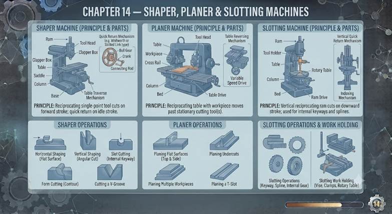
14.1 Definition of Shaper
A shaper is a reciprocating machine tool in which a single-point cutting tool mounted on a ram removes material from the workpiece during the forward cutting stroke.
Basic principle:
Reciprocating tool + stationary workpiece → Machined surface
The tool performs the reciprocating motion while the workpiece generally remains stationary.
14.2 Principle of Shaper
In a conventional shaper:
- The ram moves forward.
- The cutting tool removes material during the forward stroke.
- The ram returns during the return stroke.
- The work is given a small feed after each stroke.
- The process repeats until the required surface is obtained.
Important:
Forward stroke = Cutting stroke
Return stroke = Idle stroke
14.3 What is a Planer?
A planer is a machine tool in which the workpiece reciprocates under one or more stationary cutting tools.
This is the major difference from a shaper.
Shaper:
Tool reciprocates
Planer:
Workpiece reciprocates
14.4 What is a Slotter?
A slotting machine is essentially a vertical shaper in which the ram and cutting tool reciprocate vertically.
It is particularly useful for:
Internal slots
Keyways
Internal grooves
Internal profiles
14.5 Comparison of Shaper, Planer and Slotter
| Feature | Shaper | Planer | Slotter |
| Cutting tool | Reciprocates | Generally stationary relative to machine | Reciprocates vertically |
| Workpiece | Generally stationary | Reciprocates | Generally stationary |
| Direction | Usually horizontal | Horizontal | Vertical |
| Typical work | Small/medium | Large/heavy | Internal slots/keyways |
| Tool | Single-point | Single/multiple | Single-point |
14.6 Main Parts of a Shaper
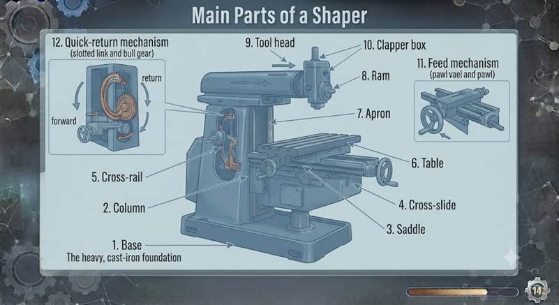
Important parts include:
- Base
- Column
- Cross rail
- Ram
- Tool head
- Clapper box
- Apron
- Table
- Saddle
- Cross-slide
- Feed mechanism
- Quick-return mechanism
14.7 Base
The base:
Supports the machine
Provides rigidity
Carries the column
It is generally made of cast iron or a suitable machine-tool material.
14.8 Column
The column is the main vertical body of the shaper.
It houses or supports:
Drive mechanism
Quick-return mechanism
Feed mechanism
14.9 Ram
The ram is one of the most important parts of the shaper.
It:
Carries the tool head
Provides reciprocating motion
Moves forward and backward
14.10 Tool Head
The tool head holds the cutting tool.
It generally provides:
Vertical tool movement
Adjustment for depth of cut
Angular positioning for inclined surfaces
14.11 Clapper Box
The clapper box is mounted on the tool head.
Its important function is:
To allow the cutting tool to lift slightly during the return stroke.
This prevents the tool from rubbing against the freshly machined surface.
Exam point:
Clapper box → Prevents tool rubbing during return stroke
14.12 Table
The table supports the workpiece.
It can generally be adjusted:
Vertically
Horizontally/crosswise depending on design
14.13 Saddle
The saddle supports the table and permits its movement.
14.14 Cross-Slide
The cross-slide allows movement of the table across the machine.
This movement is important for:
Feed
14.15 Feed Mechanism
The feed mechanism provides controlled movement of the work relative to the cutting tool.
Feed is generally given after each cutting stroke.
14.16 Quick-Return Mechanism
The quick-return mechanism is one of the most important features of a shaper.
Its purpose is to:
Make the return stroke faster than the cutting stroke.
Therefore:
This reduces idle time and increases productivity.
14.17 Common Quick-Return Mechanisms
Important mechanisms include:
1. Whitworth quick-return mechanism
2. Crank and slotted link mechanism
3. Hydraulic quick-return mechanism
14.18 Whitworth Quick-Return Mechanism
The Whitworth mechanism is a mechanical quick-return mechanism commonly associated with shaper machines.
It converts:
Rotary motion → Reciprocating motion
and provides:
Quick return
14.19 Crank and Slotted Link Mechanism
The crank and slotted link mechanism is another common mechanical arrangement for producing reciprocating motion with a quick-return characteristic.
14.20 Hydraulic Shaper
A hydraulic shaper uses hydraulic power to produce ram movement.
Advantages include:
Smooth operation
Better control
Reduced mechanical impact
Convenient speed variation
14.21 Cutting Stroke
During the cutting stroke:
Tool moves relative to work
Material is removed
Cutting force is generated
Chips are produced
14.22 Return Stroke
During the return stroke:
Tool travels back
Normally no cutting occurs
Tool may lift through the clapper mechanism
The return stroke is ideally faster.
14.23 Feed in Shaper
Feed is the movement of the workpiece relative to the tool after each stroke.
Feed may be expressed in:
mm/stroke
14.24 Depth of Cut
Depth of cut represents the thickness of material removed in one pass.
It is generally adjusted using the:
Tool head/feed mechanism
14.25 Shaper Operations
A shaper can perform:
- Horizontal surface machining
- Vertical surface machining
- Inclined surface machining
- Angular surface machining
- Slots
- Grooves
- Keyways
- Steps
- Dovetail surfaces
14.26 Horizontal Surface Machining
The shaper can produce flat horizontal surfaces by appropriately positioning the tool and work.
14.27 Vertical Surface Machining
Vertical surfaces can be produced by setting the tool head appropriately.
14.28 Inclined Surface Machining
Inclined surfaces can be produced by swivelling the tool head to the required angle.
14.29 Dovetail Machining
A shaper can produce:
Dovetail grooves and surfaces
by using a suitable tool and setting.
14.30 Slotting
Slots and grooves can be produced using appropriate shaper tools.
For internal slots, however, a slotting machine is generally more suitable.
14.31 Shaper Cutting Tool
The cutting tool used on a conventional shaper is generally:
Single-point cutting tool
The tool is similar in principle to a lathe cutting tool but is designed for reciprocating cutting.
14.32 Tool Material
Common cutting-tool materials include:
High-speed steel
Carbides
Other modern cutting-tool materials
14.33 Why a Single-Point Tool?
A single-point tool is suitable because cutting occurs during the forward stroke and the tool can be shaped to produce the required profile.
14.34 Planer Machine
A planer is designed mainly for machining:
Large and heavy workpieces.
In a planer:
Workpiece reciprocates
while:
Cutting tools are mounted on tool heads and remain stationary relative to the machine structure during the cutting movement.
14.35 Main Parts of Planer
Important parts include:
Bed
Table
Columns
Cross rail
Tool heads
Side tool heads
Drive mechanism
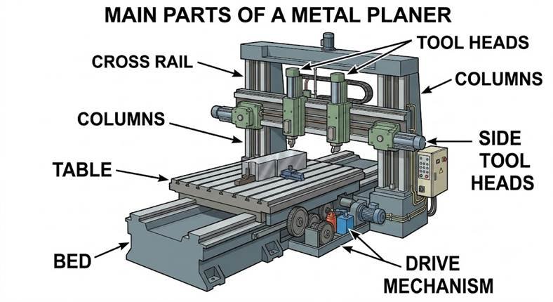
14.36 Planer Bed
The planer bed:
Supports the table
Guides table movement
Provides rigidity
14.37 Planer Table
The table carries the workpiece.
The table reciprocates:
Forward and backward
14.38 Planer Columns
Columns support the:
Cross rail and tool heads
14.39 Planer Cross Rail
The cross rail supports tool heads and can generally be adjusted vertically.
14.40 Planer Tool Heads
Planers may have multiple tool heads.
This allows:
Simultaneous machining of multiple surfaces.
14.41 Advantages of Planer
Planer is particularly advantageous for:
Large workpieces
Heavy workpieces
Long flat surfaces
Multiple cutting tools
Heavy cuts
14.42 Shaper vs Planer
Shaper
Tool reciprocates
Work remains generally stationary
Suitable for small/medium work
Usually one main cutting tool
Planer
Work reciprocates
Tools are mounted on stationary structures
Suitable for large/heavy work
Multiple tool heads possible
14.43 Slotting Machine
A slotting machine is essentially:
A vertical shaper.
The ram moves:
Vertically
14.44 Uses of Slotting Machine
Slotters are particularly useful for:
Internal keyways
Internal slots
Internal grooves
Internal splines
Internal profiles
14.45 Slotter Tool
The cutting tool is generally:
Single-point cutting tool
14.46 Slotter Applications
A slotter can be used for machining:
Keyways inside hubs
Internal slots
Small internal surfaces
Internal gear profiles in suitable applications
14.47 Cutting Speed in Shaper
Cutting speed can be expressed approximately as:
where:
= cutting speed in m/min
= cutting stroke length in metres
= number of cutting strokes per minute
If stroke length is expressed in mm:
14.48 Average Cutting Speed
Because the return stroke is generally faster than the cutting stroke, average ram speed is related to both stroke times.
If:
= stroke length
= cutting-stroke time
= return-stroke time
then:
and:
14.49 Quick-Return Ratio
The quick-return ratio is commonly expressed as:
Since return stroke is faster:
Therefore:
14.50 Important Exam Facts
Shaper
Tool reciprocates
Planer
Workpiece reciprocates
Slotter
Vertical shaper
Cutting tool
Single-point
Quick-return mechanism
Reduces return-stroke time
Clapper box
Prevents rubbing during return stroke
Planer
Large and heavy workpieces
Slotter
Internal keyways and slots
Q1. A shaper is primarily used for producing:
A. Flat surfaces
B. Round holes only
C. Gear teeth only
D. Cylindrical shafts only
Answer: A. Flat surfaces
Explanation: Shapers are particularly suitable for producing flat, inclined, stepped, grooved and similar surfaces.
Practice
Q2. In a conventional shaper, the reciprocating motion is given to the:
A. Tool
B. Workpiece
C. Table only
D. Chuck
Answer: A. Tool
Q3. In a planer, the reciprocating motion is given to the:
A. Workpiece/table
B. Cutting tool only
C. Drill
D. Tool post only
Answer: A. Workpiece/table
Q4. A slotting machine is essentially a:
A. Vertical shaper
B. Horizontal lathe
C. Milling machine
D. Grinding machine
Answer: A. Vertical shaper
Q5. The cutting tool used in a conventional shaper is generally:
A. Single-point tool
B. Multi-point drill
C. Grinding wheel
D. Reamer
Answer: A. Single-point tool
Q6. The ram of a shaper carries the:
A. Tool head
B. Motor only
C. Workpiece only
D. Coolant pump
Answer: A. Tool head
Q7. The main purpose of the quick-return mechanism is to:
A. Reduce return-stroke time
B. Increase idle time
C. Stop the cutting stroke
D. Eliminate feed
Answer: A. Reduce return-stroke time
Q8. During the forward stroke of a conventional shaper:
A. Cutting generally takes place
B. No movement occurs
C. Only coolant flows
D. The machine is switched off
Answer: A. Cutting generally takes place
Q9. The return stroke of a shaper is normally:
A. Faster than the cutting stroke
B. Slower than the cutting stroke
C. Equal in time under all mechanisms
D. The main cutting stroke
Answer: A. Faster than the cutting stroke
Q10. The clapper box is used mainly to:
A. Allow the tool to lift during return stroke
B. Drive the spindle
C. Hold the workpiece
D. Increase feed automatically
Answer: A. Allow the tool to lift during return stroke
Q11. The clapper box helps to prevent:
A. Tool rubbing during return stroke
B. Workpiece rotation
C. Coolant flow
D. Machine vibration completely
Answer: A. Tool rubbing during return stroke
Q12. The main body of a shaper that houses the driving mechanism is the:
A. Column
B. Table
C. Tool post
D. Chuck
Answer: A. Column
Q13. The workpiece in a shaper is normally mounted on the:
A. Table
B. Ram
C. Tool head
D. Clapper box
Answer: A. Table
Q14. Feed in a shaper is generally given:
A. After each cutting stroke
B. Only once during machine operation
C. During every return stroke only
D. Before mounting the work
Answer: A. After each cutting stroke
Q15. Feed in a shaper is commonly expressed in:
A. mm/stroke
B. kg/min
C. rpm only
D. m²/min
Answer: A. mm/stroke
Q16. Which mechanism is associated with quick return in a shaper?
A. Whitworth mechanism
B. Geneva mechanism only
C. Worm gear only
D. Differential screw only
Answer: A. Whitworth mechanism
Q17. A hydraulic shaper uses:
A. Hydraulic power for ram movement
B. Steam power only
C. Manual power only
D. Pneumatic cutting tools only
Answer: A. Hydraulic power for ram movement
Q18. A planer is particularly suitable for:
A. Large and heavy workpieces
B. Tiny holes only
C. Small hand tools only
D. Internal threading only
Answer: A. Large and heavy workpieces
Q19. In a planer, multiple tool heads can allow:
A. Simultaneous machining of different surfaces
B. Elimination of all cutting tools
C. Only one cut per day
D. Only drilling
Answer: A. Simultaneous machining of different surfaces
Q20. The table of a planer:
A. Reciprocates
B. Remains permanently fixed
C. Rotates continuously
D. Acts as a cutting tool
Answer: A. Reciprocates
Q21. A slotting machine is especially useful for producing:
A. Internal keyways
B. External cylindrical shafts only
C. Large external threads only
D. Flat plates only
Answer: A. Internal keyways
Q22. The ram of a slotting machine moves:
A. Vertically
B. Horizontally only
C. Circularly
D. Helically
Answer: A. Vertically
Q23. Which machine is generally preferred for very large flat surfaces?
A. Planer
B. Bench drill
C. Sensitive drill
D. Lathe
Answer: A. Planer
Q24. The quick-return mechanism converts:
A. Rotary motion into reciprocating motion
B. Reciprocating motion into heat only
C. Linear motion into welding current
D. Hydraulic pressure into casting
Answer: A. Rotary motion into reciprocating motion
Q25. Which statement is correct?
A. Shaper — tool reciprocates
B. Planer — tool always reciprocates
C. Slotter — workpiece rotates continuously
D. Shaper — drill rotates
Answer: A. Shaper — tool reciprocates
CHAPTER 14 — NEXT SECTION
MCQs 26–100 will cover the Whitworth and crank-and-slotted-link mechanisms, shaper parts, tool head, clapper box, feed mechanisms, shaper operations, planer construction, slotter applications, quick-return calculations, machining-time calculations and comparative questions.
A. SHAPER MECHANISM & PARTS — MCQs 26–45
Q26. The main function of the ram in a shaper is to:
A. Hold the workpiece
B. Provide reciprocating motion to the tool
C. Rotate the workpiece
D. Supply coolant
Answer: B. Provide reciprocating motion to the tool
Explanation: The ram carries the tool head and moves it forward and backward.
Q27. The ram of a shaper moves over the:
A. Column
B. Chuck
C. Tailstock
D. Spindle
Answer: A. Column
Q28. The table of a shaper is used to:
A. Support the workpiece
B. Rotate the tool
C. Drive the ram
D. Store cutting oil
Answer: A. Support the workpiece
Q29. The tool head of a shaper is mounted on the:
A. Ram
B. Base
C. Table
D. Cross rail
Answer: A. Ram
Q30. The tool head can generally be swivelled to machine:
A. Inclined surfaces
B. Only circular holes
C. Threads only
D. Cylindrical shafts only
Answer: A. Inclined surfaces
Q31. The clapper box is located between the:
A. Tool head and cutting tool
B. Table and base
C. Ram and column
D. Motor and belt
Answer: A. Tool head and cutting tool
Q32. The primary function of the clapper mechanism during return stroke is to:
A. Lift the tool slightly
B. Increase cutting depth
C. Increase feed
D. Rotate the tool
Answer: A. Lift the tool slightly
Q33. The cross-slide of a shaper provides:
A. Crosswise movement of the table
B. Ram rotation
C. Spindle rotation
D. Coolant movement
Answer: A. Crosswise movement of the table
Q34. The saddle of a shaper supports the:
A. Table
B. Cutting tool
C. Motor
D. Ram only
Answer: A. Table
Q35. The base of a shaper provides:
A. Foundation and support
B. Cutting action
C. Tool rotation
D. Workpiece rotation
Answer: A. Foundation and support
Q36. The feed mechanism of a shaper controls:
A. Movement of work relative to tool
B. Cutting-tool material
C. Workpiece hardness
D. Machine lubrication only
Answer: A. Movement of work relative to tool
Q37. In a conventional shaper, the workpiece generally:
A. Remains stationary during the cutting stroke
B. Rotates continuously
C. Reciprocates with the ram
D. Rotates intermittently
Answer: A. Remains stationary during the cutting stroke
Q38. A shaper is best suited for:
A. Small and medium-sized workpieces
B. Only very large ship hulls
C. Only cylindrical shafts
D. Only internal holes
Answer: A. Small and medium-sized workpieces
Q39. The quick-return mechanism is provided mainly to:
A. Reduce non-cutting time
B. Increase non-cutting time
C. Stop the return stroke
D. Eliminate cutting forces
Answer: A. Reduce non-cutting time
Q40. In a quick-return shaper:
A. Return stroke is faster
B. Cutting stroke is always faster
C. Both strokes must take equal time
D. No return stroke exists
Answer: A. Return stroke is faster
Q41. The Whitworth mechanism is also associated with:
A. Quick-return motion
B. Gear cutting only
C. Grinding only
D. Drilling only
Answer: A. Quick-return motion
Q42. The crank and slotted-link mechanism converts rotary motion into:
A. Reciprocating motion
B. Pure rotary motion
C. Vibratory motion only
D. Helical motion only
Answer: A. Reciprocating motion
Q43. In a hydraulic shaper, ram motion is produced by:
A. Hydraulic pressure
B. Gravity alone
C. Manual filing
D. Centrifugal force only
Answer: A. Hydraulic pressure
Q44. One advantage of a hydraulic shaper is:
A. Smooth ram movement
B. No need for a tool
C. No cutting force
D. No workpiece support
Answer: A. Smooth ram movement
Q45. The cutting tool in a shaper generally has:
A. A single cutting point
B. Hundreds of cutting teeth
C. No cutting edge
D. Only abrasive grains
Answer: A. A single cutting point
B. SHAPER OPERATIONS — MCQs 46–60
Q46. A shaper can machine:
A. Horizontal surfaces
B. Vertical surfaces
C. Inclined surfaces
D. All of the above
Answer: D. All of the above
Q47. To machine an inclined surface, the tool head may be:
A. Swivelled
B. Removed
C. Welded to the table
D. Rotated at high speed
Answer: A. Swivelled
Q48. A shaper can produce:
A. Slots
B. Grooves
C. Steps
D. All of the above
Answer: D. All of the above
Q49. A dovetail surface can be produced using:
A. A suitable shaper operation
B. Only drilling
C. Only reaming
D. Only tapping
Answer: A. A suitable shaper operation
Q50. The cutting stroke of a shaper is also called the:
A. Forward stroke
B. Return stroke
C. Idle stroke
D. Reverse stroke
Answer: A. Forward stroke
Q51. The return stroke is generally:
A. Non-cutting
B. The main cutting stroke
C. Used for drilling
D. Used for casting
Answer: A. Non-cutting
Q52. The tool is fed into the workpiece mainly:
A. After each stroke
B. Only once at the beginning
C. Continuously during the return stroke only
D. Never
Answer: A. After each stroke
Q53. The feed direction for machining a horizontal surface is generally:
A. Across the surface
B. Vertically downward only
C. Circularly
D. Randomly
Answer: A. Across the surface
Q54. The depth of cut in a shaper is controlled by:
A. Adjusting the tool/work position
B. Changing coolant colour
C. Increasing workpiece weight
D. Removing the base
Answer: A. Adjusting the tool/work position
Q55. Shaping is generally considered suitable for:
A. Low-to-medium production and general machining
B. Only mass production of identical parts
C. Only casting
D. Heat treatment
Answer: A. Low-to-medium production and general machining
Q56. Compared with milling, shaping generally has:
A. Intermittent cutting
B. Continuous cutting by rotating teeth
C. No cutting stroke
D. Only abrasive cutting
Answer: A. Intermittent cutting
Q57. One disadvantage of a shaper is:
A. Significant idle return stroke
B. No cutting tool
C. No possibility of flat surfaces
D. No feed mechanism
Answer: A. Significant idle return stroke
Q58. The quick-return mechanism improves:
A. Productivity
B. Workpiece hardness
C. Tool colour
D. Material composition
Answer: A. Productivity
Q59. Shaper cutting is:
A. Intermittent
B. Continuous rotary cutting
C. Non-machining
D. Casting
Answer: A. Intermittent
Q60. Which operation is NOT normally associated with a conventional shaper?
A. Flat surface machining
B. Slotting
C. Inclined surface machining
D. Deep-hole drilling
Answer: D. Deep-hole drilling
C. PLANER MACHINE — MCQs 61–75
Q61. In a planer, the main reciprocating member is the:
A. Table
B. Cutting tool
C. Drill spindle
D. Chuck
Answer: A. Table
Q62. A planer is mainly used for:
A. Large and heavy workpieces
B. Small holes
C. Internal threading only
D. Small shaft turning
Answer: A. Large and heavy workpieces
Q63. The workpiece in a planer is mounted on the:
A. Reciprocating table
B. Tool head
C. Column
D. Cross rail only
Answer: A. Reciprocating table
Q64. Planer tool heads are generally mounted on:
A. Cross rail and/or side supports
B. Lathe tailstock
C. Drill chuck
D. Shaper ram
Answer: A. Cross rail and/or side supports
Q65. A major advantage of a planer is:
A. It can accommodate very large workpieces
B. It is limited to tiny components
C. It cannot machine flat surfaces
D. It cannot use multiple tools
Answer: A. It can accommodate very large workpieces
Q66. Multiple tool heads on a planer allow:
A. Simultaneous machining
B. Elimination of feed
C. Elimination of cutting tools
D. Only drilling
Answer: A. Simultaneous machining
Q67. The bed of a planer supports and guides the:
A. Table
B. Drill
C. Chuck
D. Cutting insert only
Answer: A. Table
Q68. The columns of a planer support the:
A. Cross rail
B. Workpiece directly only
C. Drill chuck
D. Lathe spindle
Answer: A. Cross rail
Q69. The cross rail of a planer carries:
A. Tool heads
B. Lathe chuck
C. Tailstock
D. Drill spindle
Answer: A. Tool heads
Q70. A planer can machine:
A. Large flat surfaces
B. Steps
C. Slots and grooves
D. All of the above
Answer: D. All of the above
Q71. The main difference between a shaper and planer is:
A. Tool reciprocates in shaper; work reciprocates in planer
B. Both have identical motion
C. Work reciprocates in shaper only
D. Tool rotates in both
Answer: A. Tool reciprocates in shaper; work reciprocates in planer
Q72. Compared with a shaper, a planer generally has:
A. Greater capacity
B. Smaller capacity
C. No table
D. No cutting tool
Answer: A. Greater capacity
Q73. A planer is suitable for heavy cuts because of its:
A. Rigid construction
B. Small size
C. Hand operation
D. Lack of feed
Answer: A. Rigid construction
Q74. The table of a planer generally moves:
A. Horizontally
B. Vertically only
C. Circularly
D. Helically
Answer: A. Horizontally
Q75. In a planer, the cutting tool is generally:
A. Stationary relative to the tool-support structure while the work/table reciprocates
B. Rotating continuously like a milling cutter
C. A drill
D. A grinding wheel
Answer: A. Stationary relative to the tool-support structure while the work/table reciprocates
D. SLOTTING MACHINE — MCQs 76–85
Q76. A slotting machine is essentially a:
A. Vertical shaper
B. Horizontal planer
C. Lathe
D. Milling machine
Answer: A. Vertical shaper
Q77. The ram of a slotter moves:
A. Vertically
B. Horizontally
C. Circularly
D. Helically
Answer: A. Vertically
Q78. A slotter is especially suitable for machining:
A. Internal keyways
B. External cylindrical surfaces
C. External threads
D. Long shafts
Answer: A. Internal keyways
Q79. A slotting machine can be used to machine:
A. Internal grooves
B. Internal slots
C. Internal profiles
D. All of the above
Answer: D. All of the above
Q80. The cutting tool in a slotter is generally:
A. Single-point tool
B. Twist drill
C. Reamer
D. Milling cutter
Answer: A. Single-point tool
Q81. Slotting is particularly useful where:
A. Internal surfaces are difficult to reach with other machines
B. Only external turning is required
C. Only drilling is required
D. Only grinding is required
Answer: A. Internal surfaces are difficult to reach with other machines
Q82. A keyway inside a gear or pulley hub can commonly be produced using:
A. Slotting machine
B. Surface grinder only
C. Drill chuck only
D. Lathe centre only
Answer: A. Slotting machine
Q83. In a slotter, the workpiece generally:
A. Remains stationary while the tool reciprocates vertically
B. Rotates continuously
C. Reciprocates horizontally
D. Rotates at high speed
Answer: A. Remains stationary while the tool reciprocates vertically
Q84. The slotter is particularly suitable for:
A. Internal machining
B. External turning
C. External cylindrical grinding
D. Deep-hole drilling
Answer: A. Internal machining
Q85. Which statement is correct?
A. Slotter — vertical reciprocating tool
B. Slotter — rotating workpiece
C. Slotter — horizontal drilling
D. Slotter — continuous milling cutter
Answer: A. Slotter — vertical reciprocating tool
E. NUMERICAL & QUICK-RETURN QUESTIONS — MCQs 86–100
Q86. If the cutting stroke takes 6 seconds and return stroke takes 4 seconds, the quick-return ratio is:
A. 0.67
B. 1.0
C. 1.5
D. 2.5
Answer: C. 1.5
Q87. If cutting-stroke time is 10 seconds and return-stroke time is 5 seconds, quick-return ratio is:
A. 0.5
B. 1
C. 2
D. 5
Answer: C. 2
Q88. If the cutting stroke takes 8 seconds and return stroke takes 4 seconds, total time per cycle is:
A. 4 s
B. 8 s
C. 12 s
D. 32 s
Answer: C. 12 s
Q89. A shaper makes 10 complete strokes per minute. The number of cutting strokes per minute is:
A. 5
B. 10
C. 20
D. 30
Answer: A. 5
Explanation: One complete cycle contains one cutting stroke and one return stroke.
Q90. If a shaper performs 20 cutting strokes per minute, the number of complete cycles per minute is:
A. 10
B. 20
C. 40
D. 5
Answer: B. 20
Explanation: Each cycle has one cutting stroke and one return stroke.
Q91. A shaper has a stroke length of 500 mm and performs 20 cutting strokes/min. The cutting speed is:
A. 5 m/min
B. 10 m/min
C. 20 m/min
D. 40 m/min
Answer: B. 10 m/min
Q92. A shaper has a stroke length of 600 mm and makes 30 cutting strokes/min. Cutting speed is:
A. 12 m/min
B. 18 m/min
C. 24 m/min
D. 30 m/min
Answer: B. 18 m/min
Q93. A shaper makes 15 cutting strokes/min and has a stroke length of 400 mm. Cutting speed is:
A. 4 m/min
B. 6 m/min
C. 8 m/min
D. 10 m/min
Answer: B. 6 m/min
Q94. If cutting speed is 12 m/min and stroke length is 600 mm, the number of cutting strokes per minute is:
A. 10
B. 15
C. 20
D. 30
Answer: C. 20
Q95. If a shaper makes 12 complete cycles per minute, the total number of strokes per minute is:
A. 6
B. 12
C. 24
D. 36
Answer: C. 24
Q96. A workpiece requires 100 strokes and the machine makes 20 cutting strokes/min. Approximate machining time, ignoring setup and other allowances, is:
A. 2 min
B. 5 min
C. 10 min
D. 20 min
Answer: B. 5 min
Q97. If the return stroke takes less time than the cutting stroke, the quick-return ratio is:
A. Greater than 1
B. Less than 1
C. Equal to zero
D. Always equal to 1
Answer: A. Greater than 1
Q98. A machine has cutting-stroke time of 9 seconds and return-stroke time of 3 seconds. Its quick-return ratio is:
A. 1
B. 2
C. 3
D. 6
Answer: C. 3
Q99. If a shaper has a cutting speed of 15 m/min and stroke length of 750 mm, cutting strokes per minute are:
A. 10
B. 15
C. 20
D. 25
Answer: C. 20
Q100. Which sequence correctly represents the machines?
A. Shaper — horizontal reciprocating tool; Planer — reciprocating work; Slotter — vertical reciprocating tool
B. Shaper — rotating tool; Planer — rotating work; Slotter — rotating tool
C. Shaper — drilling; Planer — turning; Slotter — grinding
D. Shaper — only vertical motion; Planer — only rotary motion; Slotter — only drilling
Answer: A. Shaper — horizontal reciprocating tool; Planer — reciprocating work; Slotter — vertical reciprocating tool
CHAPTER 14 — EXAM REVISION TABLE
| Topic | Remember |
| Shaper | Tool reciprocates |
| Planer | Workpiece/table reciprocates |
| Slotter | Vertical shaper |
| Shaper tool | Single-point |
| Cutting stroke | Forward stroke |
| Return stroke | Non-cutting/idle |
| Quick return | Faster return |
| Clapper box | Prevents tool rubbing |
| Whitworth | Quick-return mechanism |
| Hydraulic shaper | Hydraulic ram drive |
| Shaper feed | Commonly mm/stroke |
| Planer | Large/heavy work |
| Planer table | Reciprocates |
| Planer tool heads | Multiple tools possible |
| Slotter | Internal keyways/slots |
| Slotter ram | Vertical |
| Cutting speed | |
| Quick-return ratio |
CHAPTER 15 : MILLING MACHINE & MILLING OPERATIONS
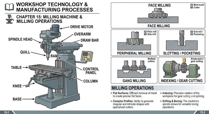
15.1 Definition of Milling
Milling is a machining process in which material is removed from a workpiece by a rotating multi-point cutting tool.
The milling cutter contains several cutting teeth.
Key point
Milling = Rotating multi-point cutter + workpiece feed
This distinguishes milling from turning and shaping.
15.2 Principle of Milling
During milling:
- The cutter rotates.
- The workpiece is securely clamped.
- The workpiece is fed against the rotating cutter.
- Cutter teeth remove material intermittently.
- Chips are produced.
- The desired surface/profile is obtained.
15.3 Main Characteristics of Milling
Milling generally involves:
Rotating cutting tool
Multiple cutting edges
Intermittent cutting
Relative movement between cutter and work
Material removal in the form of chips
15.4 Milling Cutter
A milling cutter is a rotary multi-point cutting tool having several cutting teeth arranged around its circumference and/or face.
Examples:
Plain milling cutter
End mill
Side milling cutter
Slitting saw
Angle cutter
Form cutter
Gear cutter
T-slot cutter
Face mill
15.5 Milling Machine
A milling machine is a machine tool designed primarily to machine surfaces using a rotating multi-point cutter.
It can produce:
Flat surfaces
Slots
Grooves
Keyways
Steps
Angular surfaces
Gear teeth
Helical surfaces
Profiles
15.6 Types of Milling Machines
Important types include:
- Column and knee type
- Horizontal milling machine
- Vertical milling machine
- Universal milling machine
- Fixed-bed milling machine
- Planer-type milling machine
- CNC milling machine
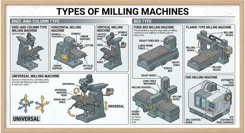
15.7 Horizontal Milling Machine
In a horizontal milling machine:
The spindle axis is horizontal.
The cutter is mounted on the spindle/arbor.
It is particularly suitable for:
Slab milling
Side milling
Groove milling
Heavy-duty milling
15.8 Vertical Milling Machine
In a vertical milling machine:
The spindle axis is vertical.
It is commonly used for:
Face milling
End milling
Slot milling
Drilling-like operations
Profile machining
15.9 Universal Milling Machine
A universal milling machine is similar to a horizontal milling machine but has a table that can be swivelled, allowing additional angular/helix-related operations.
It is particularly useful for:
Helical milling
Gear cutting
Angular milling
Complex machining
15.10 Column and Knee Type Milling Machine
Major components include:
Base
Column
Knee
Saddle
Table
Spindle
Arbor
Overarm
15.11 Column
The column:
Supports the machine structure
Houses the drive mechanism
Supports the knee
15.12 Knee
The knee is mounted on the column and supports the:
Saddle and table.
It can move vertically.
15.13 Saddle
The saddle is located between the:
Knee and table.
It generally provides crosswise movement of the table.
15.14 Table
The table supports and clamps the workpiece.
It provides longitudinal movement.
15.15 Spindle
The spindle provides rotary motion to the milling cutter.
In a horizontal milling machine, the spindle usually drives the arbor/cutter.
15.16 Arbor
The arbor is used mainly with horizontal milling machines to:
Support and drive milling cutters.
15.17 Overarm
The overarm supports the arbor in many horizontal milling machines.
15.18 Milling Cutter Classification
Milling cutters may be classified according to:
Position of teeth
Peripheral cutters
Face cutters
End cutters
Function
Plain cutter
Side cutter
Slitting saw
Angle cutter
Form cutter
Gear cutter
15.19 Plain Milling Cutter
A plain milling cutter has teeth mainly on its:
Peripheral surface.
It is commonly used for producing:
Flat horizontal surfaces.
15.20 Face Milling Cutter
A face milling cutter has cutting edges on:
Face
Sometimes periphery
It is used primarily for:
Machining flat surfaces.
15.21 Side Milling Cutter
A side milling cutter has teeth on:
Side and peripheral surfaces.
It is commonly used for:
Slots
Grooves
Side surfaces
15.22 End Mill
An end mill has cutting edges on its:
End
Periphery
It is used for:
Slots
Pockets
Profiles
Keyways
15.23 Slitting Saw
A slitting saw is a thin circular cutter used for:
Narrow slots
Grooves
Cutting-off operations
15.24 Angle Cutter
Angle milling cutters are used for producing:
Inclined/angular surfaces and grooves.
15.25 Form Cutter
A form cutter has a specially shaped cutting profile.
It is used for producing:
Corresponding shaped surfaces.
15.26 Up Milling
In up milling:
The cutter rotates opposite to the direction of work feed at the point of cutting.
It is also called:
Conventional milling.
Important characteristic:
Chip thickness generally starts at:
Zero
and increases toward the maximum value.
15.27 Down Milling
In down milling:
The cutter rotates in the same direction as the work feed at the point of cutting.
It is also called:
Climb milling.
The chip thickness generally:
Starts at maximum and decreases toward zero.
15.28 Comparison of Up and Down Milling
| Feature | Up Milling | Down Milling |
| Other name | Conventional milling | Climb milling |
| Cutter rotation | Opposite feed | Same direction as feed |
| Chip thickness | 0 → maximum | Maximum → 0 |
| Cutting force | Tends to lift work | Tends to press work down |
| Backlash concern | Less critical | More critical |
| Surface finish | Generally lower | Generally better |
15.29 Advantages of Up Milling
Suitable for machines with some backlash
Cutting starts with small chip thickness
Generally safer on conventional machines
Cutting force tends to lift the work
15.30 Advantages of Down Milling
Better surface finish under suitable conditions
Reduced tendency for rubbing
Lower tendency for workpiece lifting
Often more efficient
Important:
Down milling requires proper machine condition and backlash control.
15.31 Conventional Milling
Another name for:
Up milling
15.32 Climb Milling
Another name for:
Down milling
15.33 Milling Feed
Feed can be expressed as:
mm/min
mm/rev
mm/tooth
For milling, feed per tooth is particularly important.
15.34 Feed Rate Formula
If:
= feed per tooth
= number of teeth
= spindle speed
then:
where is feed rate in mm/min.
15.35 Milling Cutting Speed
The cutting-speed formula is:
where:
= cutting speed in m/min
= cutter diameter in mm
= spindle speed in rpm
15.36 Milling Machining Time
For a simple milling operation:
where:
= machining time
= effective travel
= feed rate
15.37 Indexing
Indexing is the process of rotating the workpiece through a predetermined angular amount between successive machining operations.
It is especially important for:
Gear teeth
Splines
Polygonal surfaces
Equally spaced slots
15.38 Dividing Head
A dividing head is used for:
Indexing the workpiece accurately.
It is commonly used in:
Gear cutting
Slot cutting
Polygon machining
Helical milling
15.39 Simple Indexing
For a standard 40:1 dividing head:
where is the number of divisions required.
Example:
For 20 divisions:
Therefore, the crank is turned 2 complete revolutions per division.
15.40 Differential Indexing
Differential indexing is used when the required indexing cannot conveniently be achieved by simple indexing.
The dividing-head spindle receives additional rotation through the gear train.
15.41 Helical Milling
Helical surfaces can be produced using:
Universal milling machine
Dividing head
Suitable gearing
Applications include:
Helical gears
Spiral grooves
Helical splines
15.42 Gear Cutting
Gear teeth can be produced by milling using:
Form-relieved gear cutters
A dividing head is used to index the blank between teeth.
15.43 T-Slot Milling
T-slots are produced using:
T-slot cutters
These are commonly used for producing T-slots in machine-tool tables and fixtures.
15.44 Keyway Milling
Keyways can be produced using:
End mills or suitable slot/keyway cutters.
15.45 Straddle Milling
Straddle milling uses:
Two side milling cutters
mounted on the same arbor to machine two parallel surfaces simultaneously.
15.46 Gang Milling
Gang milling involves:
Two or more cutters mounted on the same arbor to perform multiple operations in one pass.
15.47 Important Exam Facts
Milling cutter → Multi-point
Plain milling → Peripheral teeth
Face milling → Face surface machining
Up milling → Conventional milling
Down milling → Climb milling
Up milling → Chip thickness 0 to maximum
Down milling → Maximum to 0
Dividing head → Indexing
Standard dividing-head ratio → 40:1
Feed rate →
Cutting speed →
Straddle milling → Two side cutters
Gang milling → Multiple cutters
T-slot → T-slot cutter
Q1. Milling is a machining process using a:
A. Single-point stationary tool
B. Rotating multi-point cutting tool
C. Grinding wheel only
D. Single-point rotating tool only
Answer: B. Rotating multi-point cutting tool
Explanation: A milling cutter has multiple cutting teeth and rotates during machining.
Q2. In a milling machine, the cutting tool generally:
A. Rotates
B. Remains permanently stationary
C. Reciprocates only
D. Does not move
Answer: A. Rotates
Q3. A milling cutter is generally a:
A. Multi-point cutting tool
B. Single-point tool
C. Non-cutting tool
D. Measuring tool
Answer: A. Multi-point cutting tool
Q4. The spindle axis of a horizontal milling machine is:
A. Horizontal
B. Vertical
C. Inclined at 45° always
D. Circular
Answer: A. Horizontal
Q5. In a vertical milling machine, the spindle axis is:
A. Vertical
B. Horizontal
C. Parallel to table only
D. Random
Answer: A. Vertical
Q6. A plain milling cutter has teeth primarily on its:
A. Periphery
B. End face only
C. Shank
D. Arbor
Answer: A. Periphery
Q7. A face milling cutter is mainly used for:
A. Flat surface machining
B. Internal threading
C. Drilling deep holes
D. Knurling
Answer: A. Flat surface machining
Q8. A side milling cutter is particularly suitable for:
A. Slots and grooves
B. Drilling holes
C. External threading
D. Grinding
Answer: A. Slots and grooves
Q9. An end mill has cutting edges on:
A. End and periphery
B. Shank only
C. Arbor only
D. Face only
Answer: A. End and periphery
Q10. A slitting saw is used mainly for:
A. Narrow slots and cutting-off
B. Drilling
C. Reaming
D. Tapping
Answer: A. Narrow slots and cutting-off
Q11. In up milling, the cutter rotates:
A. Opposite to the feed direction at the cutting point
B. In the same direction as feed
C. Without rotation
D. Vertically only
Answer: A. Opposite to the feed direction at the cutting point
Q12. Up milling is also called:
A. Conventional milling
B. Climb milling
C. Face turning
D. Slotting
Answer: A. Conventional milling
Q13. Down milling is also called:
A. Climb milling
B. Conventional milling
C. Plain turning
D. Back machining
Answer: A. Climb milling
Q14. In down milling, cutter rotation and work feed are:
A. In the same direction at the cutting point
B. Always opposite
C. Unrelated
D. Both stationary
Answer: A. In the same direction at the cutting point
Q15. In up milling, chip thickness generally:
A. Starts at zero and increases
B. Starts at maximum and decreases
C. Remains zero
D. Remains constant
Answer: A. Starts at zero and increases
Q16. In down milling, chip thickness generally:
A. Starts at maximum and decreases
B. Starts at zero and increases
C. Remains zero
D. Remains constant
Answer: A. Starts at maximum and decreases
Q17. Conventional milling is generally more tolerant of:
A. Backlash
B. Excessive vibration
C. Broken cutters
D. No lubrication
Answer: A. Backlash
Q18. Climb milling generally requires:
A. Proper backlash control
B. No machine rigidity
C. Loose table movement
D. No work holding
Answer: A. Proper backlash control
Q19. The formula for milling cutting speed is:
A.
B.
C.
D.
Answer: A.
Q20. If feed per tooth is , number of teeth is , and spindle speed is , feed rate is:
A.
B.
C.
D.
Answer: A.
Q21. A dividing head is primarily used for:
A. Indexing
B. Grinding
C. Welding
D. Drilling
Answer: A. Indexing
Q22. The standard ratio of a common dividing head is:
A. 20:1
B. 30:1
C. 40:1
D. 60:1
Answer: C. 40:1
Q23. The crank movement for simple indexing with a 40:1 dividing head is:
A.
B.
C.
D.
Answer: B.
Q24. Straddle milling uses:
A. Two side milling cutters
B. One drill
C. One reamer
D. One grinding wheel
Answer: A. Two side milling cutters
Q25. Gang milling involves:
A. Several cutters mounted together to perform multiple operations
B. One cutter used repeatedly
C. Only a drill
D. Only a reamer
Answer: A. Several cutters mounted together to perform multiple operations
A. MILLING MACHINE PARTS — MCQs 26–40
Q26. The knee of a column-and-knee milling machine is mounted on the:
A. Table
B. Column
C. Arbor
D. Spindle
Answer: B. Column
Explanation: The knee slides vertically on the column and supports the saddle and table.
Q27. The saddle is located between the:
A. Column and spindle
B. Knee and table
C. Table and arbor
D. Base and spindle
Answer: B. Knee and table
Q28. The table of a conventional milling machine primarily provides:
A. Support and movement for the workpiece
B. Rotation to the cutter
C. Hydraulic pressure
D. Cutting-fluid filtration
Answer: A. Support and movement for the workpiece
Q29. In a horizontal milling machine, the arbor is used to:
A. Support and drive the cutter
B. Support the workpiece only
C. Measure cutting speed
D. Produce coolant
Answer: A. Support and drive the cutter
Q30. The overarm in a horizontal milling machine primarily supports the:
A. Arbor
B. Table
C. Knee
D. Workpiece
Answer: A. Arbor
Q31. The column of a milling machine provides support for the:
A. Knee and other machine components
B. Workpiece only
C. Cutter teeth
D. Vice jaws only
Answer: A. Knee and other machine components
Q32. The spindle of a milling machine is responsible for:
A. Rotating the milling cutter
B. Supporting the machine foundation
C. Holding the workpiece directly in all cases
D. Supplying coolant
Answer: A. Rotating the milling cutter
Q33. In a vertical milling machine, the cutter is generally mounted:
A. Directly in or on the spindle
B. Only on a horizontal arbor
C. On the tailstock
D. On the lathe carriage
Answer: A. Directly in or on the spindle
Q34. The knee provides:
A. Vertical movement
B. Cutter tooth grinding
C. Spindle rotation
D. Coolant filtration
Answer: A. Vertical movement
Q35. The saddle generally provides:
A. Cross movement of the table
B. Spindle rotation
C. Vertical tool rotation
D. Cutting-fluid pressure
Answer: A. Cross movement of the table
Q36. The longitudinal movement of a conventional milling-machine table is generally along the:
A. X-axis
B. Y-axis
C. Z-axis only
D. Rotary axis
Answer: A. X-axis
Q37. The cross movement of the table is generally along the:
A. Y-axis
B. X-axis
C. Z-axis
D. C-axis only
Answer: A. Y-axis
Q38. Vertical movement in a conventional column-and-knee milling machine is generally associated with the:
A. Z-axis
B. X-axis
C. Y-axis
D. A-axis
Answer: A. Z-axis
Q39. The workpiece is commonly held on a milling machine using:
A. Vice, clamps or suitable fixtures
B. Only a drill chuck
C. Only a tailstock
D. Only a lathe dog
Answer: A. Vice, clamps or suitable fixtures
Q40. The primary function of a machine vice is to:
A. Hold the workpiece securely
B. Rotate the cutter
C. Drive the spindle
D. Supply coolant
Answer: A. Hold the workpiece securely
B. MILLING CUTTERS — MCQs 41–55
Q41. A plain milling cutter is primarily used for:
A. Producing flat horizontal surfaces
B. Producing internal threads
C. Drilling holes
D. Grinding surfaces
Answer: A. Producing flat horizontal surfaces
Q42. A side milling cutter has teeth on:
A. Side and periphery
B. Shank only
C. Arbor only
D. Face only
Answer: A. Side and periphery
Q43. A face mill is primarily used for:
A. Face milling
B. Tapping
C. Reaming
D. Knurling
Answer: A. Face milling
Q44. An end mill can be used for:
A. Slots and pockets
B. Profiles
C. Keyways
D. All of the above
Answer: D. All of the above
Q45. A T-slot cutter is used for:
A. Producing T-slots
B. Producing circular holes
C. Cutting external threads
D. Grinding gears
Answer: A. Producing T-slots
Q46. An angle cutter is used for:
A. Angular surfaces and grooves
B. Drilling holes
C. Turning shafts
D. Honing
Answer: A. Angular surfaces and grooves
Q47. A form cutter is designed to produce:
A. A specific profile
B. Only a flat surface
C. Only a round hole
D. External threads only
Answer: A. A specific profile
Q48. A gear milling cutter is used for:
A. Cutting gear teeth
B. Drilling gear blanks
C. Grinding bearings
D. Producing welds
Answer: A. Cutting gear teeth
Q49. A slitting saw is generally:
A. Thin compared with its diameter
B. Very thick and solid
C. A single-point tool
D. A grinding wheel
Answer: A. Thin compared with its diameter
Q50. A slitting saw is particularly suitable for:
A. Narrow slots
B. Deep drilling
C. Thread tapping
D. Surface grinding
Answer: A. Narrow slots
Q51. A shell-end mill is generally mounted using:
A. A suitable arbor/holder
B. A lathe tailstock
C. A drill table only
D. A steady rest
Answer: A. A suitable arbor/holder
Q52. The cutting edges of a milling cutter are called:
A. Teeth
B. Margins
C. Lips only
D. Flutes only
Answer: A. Teeth
Q53. The space between adjacent milling-cutter teeth is called:
A. Tooth space
B. Web
C. Margin
D. Shank
Answer: A. Tooth space
Q54. The body of a milling cutter supports:
A. Cutting teeth
B. Workpiece only
C. Machine table
D. Coolant tank
Answer: A. Cutting teeth
Q55. The number of teeth on a milling cutter affects:
A. Feed rate and cutting action
B. Workpiece chemical composition
C. Machine foundation
D. Coolant colour
Answer: A. Feed rate and cutting action
C. UP MILLING & DOWN MILLING — MCQs 56–70
Q56. Up milling is also known as:
A. Conventional milling
B. Climb milling
C. Reverse turning
D. Face turning
Answer: A. Conventional milling
Q57. Down milling is also called:
A. Climb milling
B. Conventional milling
C. Reverse drilling
D. Plain milling
Answer: A. Climb milling
Q58. In up milling, chip thickness:
A. Starts from approximately zero
B. Starts from maximum
C. Remains constant
D. Is always zero
Answer: A. Starts from approximately zero
Q59. In down milling, chip thickness:
A. Starts approximately at maximum
B. Starts at zero
C. Remains constant
D. Does not exist
Answer: A. Starts approximately at maximum
Q60. In up milling, cutting force tends to:
A. Lift the workpiece from the table
B. Press the workpiece firmly down
C. Eliminate all vibration
D. Stop the cutter
Answer: A. Lift the workpiece from the table
Q61. In down milling, cutting force tends to:
A. Press the workpiece against the table
B. Lift the workpiece
C. Stop feed completely
D. Reverse spindle rotation
Answer: A. Press the workpiece against the table
Q62. Down milling is generally preferred when:
A. Machine backlash is properly controlled
B. The machine has excessive backlash
C. The workpiece is loose
D. The cutter is not rotating
Answer: A. Machine backlash is properly controlled
Q63. In up milling, the cutter and work feed at the cutting point move:
A. In opposite directions
B. In the same direction
C. Vertically only
D. Without relative movement
Answer: A. In opposite directions
Q64. In down milling, cutter rotation and feed at the cutting point are:
A. In the same direction
B. In opposite directions
C. Always perpendicular
D. Both stationary
Answer: A. In the same direction
Q65. Which milling method generally gives better surface finish under suitable conditions?
A. Down milling
B. Up milling
C. Neither
D. Both always identical
Answer: A. Down milling
Q66. A major disadvantage of down milling on a machine with excessive backlash is:
A. Possibility of cutter grabbing/pulling the work
B. Zero cutting force
C. No chip formation
D. No surface generation
Answer: A. Possibility of cutter grabbing/pulling the work
Q67. In conventional milling, the cutting tooth generally enters the work with:
A. Minimum chip thickness
B. Maximum chip thickness
C. Zero cutting velocity
D. No contact
Answer: A. Minimum chip thickness
Q68. In climb milling, the cutting tooth generally enters the work with:
A. Maximum chip thickness
B. Zero chip thickness
C. No chip
D. Constant thickness
Answer: A. Maximum chip thickness
Q69. The term “climb” in climb milling refers to:
A. Feed and cutter motion being in the same direction at the cutting point
B. Vertical movement of the table only
C. Cutter moving upward
D. Workpiece moving vertically
Answer: A. Feed and cutter motion being in the same direction at the cutting point
Q70. Which statement is correct?
A. Up milling is generally more suitable for machines with backlash
B. Down milling requires no machine rigidity
C. Up milling always gives the best finish
D. Down milling is impossible on CNC machines
Answer: A. Up milling is generally more suitable for machines with backlash
D. INDEXING & GEAR CUTTING — MCQs 71–85
Q71. Indexing means:
A. Dividing the workpiece circumference into predetermined equal or unequal divisions
B. Grinding the workpiece
C. Measuring cutting temperature
D. Changing tool material
Answer: A. Dividing the workpiece circumference into predetermined equal or unequal divisions
Q72. The dividing head is commonly used for:
A. Gear cutting
B. Equal-spaced slots
C. Polygonal machining
D. All of the above
Answer: D. All of the above
Q73. A standard dividing head commonly has a worm ratio of:
A. 10:1
B. 20:1
C. 40:1
D. 100:1
Answer: C. 40:1
Q74. For a 40:1 dividing head, crank movement for divisions is:
A.
B.
C.
D.
Answer: B.
Q75. For 10 divisions, the crank movement using a 40:1 dividing head is:
A. 2 revolutions
B. 4 revolutions
C. 10 revolutions
D. 40 revolutions
Answer: B. 4 revolutions
Q76. For 20 divisions, crank movement is:
A. 1 revolution
B. 2 revolutions
C. 4 revolutions
D. 20 revolutions
Answer: B. 2 revolutions
Q77. For 40 divisions, crank movement is:
A. 0.5 revolution
B. 1 revolution
C. 2 revolutions
D. 4 revolutions
Answer: B. 1 revolution
Q78. For 8 divisions, crank movement is:
A. 2 revolutions
B. 4 revolutions
C. 5 revolutions
D. 8 revolutions
Answer: C. 5 revolutions
Q79. For 16 divisions, crank movement is:
A. 1.5 revolutions
B. 2.5 revolutions
C. 4 revolutions
D. 5 revolutions
Answer: B. 2.5 revolutions
Q80. A dividing head is especially important in machining:
A. Equally spaced features
B. Only flat surfaces
C. Only holes
D. Only cylindrical surfaces
Answer: A. Equally spaced features
Q81. Gear teeth can be cut on a milling machine using:
A. Gear milling cutter and indexing arrangement
B. Drill only
C. Reamer only
D. Grinding wheel only
Answer: A. Gear milling cutter and indexing arrangement
Q82. In conventional form milling of gears, the gear blank is indexed:
A. Between successive teeth
B. Only once
C. Continuously without stopping
D. Only after finishing the entire gear
Answer: A. Between successive teeth
Q83. Helical milling generally requires:
A. Universal milling machine and suitable indexing arrangement
B. Only a bench drill
C. Only a shaper
D. Only a grinding machine
Answer: A. Universal milling machine and suitable indexing arrangement
Q84. Differential indexing is useful when:
A. Simple indexing cannot conveniently provide the required division
B. No indexing is needed
C. Only drilling is performed
D. The cutter is broken
Answer: A. Simple indexing cannot conveniently provide the required division
Q85. The dividing head allows the workpiece to be:
A. Rotated accurately through predetermined angular increments
B. Heated
C. Ground automatically
D. Welded
Answer: A. Rotated accurately through predetermined angular increments
E. MILLING CALCULATIONS — MCQs 86–100
Q86. A milling cutter of diameter 100 mm rotates at 300 rpm. Cutting speed is approximately:
A. 47.1 m/min
B. 94.2 m/min
C. 120 m/min
D. 300 m/min
Answer: B. 94.2 m/min
Q87. A 50 mm cutter rotates at 600 rpm. Cutting speed is approximately:
A. 47.1 m/min
B. 94.2 m/min
C. 120 m/min
D. 188.5 m/min
Answer: B. 94.2 m/min
Q88. A milling cutter of 80 mm diameter rotates at 500 rpm. Cutting speed is approximately:
A. 62.8 m/min
B. 100 m/min
C. 125.7 m/min
D. 160 m/min
Answer: C. 125.7 m/min
Q89. A cutter has 10 teeth, feed per tooth is 0.05 mm and spindle speed is 400 rpm. Feed rate is:
A. 20 mm/min
B. 100 mm/min
C. 200 mm/min
D. 400 mm/min
Answer: C. 200 mm/min
Q90. A cutter has 8 teeth, feed per tooth is 0.1 mm and speed is 500 rpm. Feed rate is:
A. 200 mm/min
B. 300 mm/min
C. 400 mm/min
D. 500 mm/min
Answer: C. 400 mm/min
Q91. If feed per tooth is 0.08 mm, number of teeth is 10 and speed is 600 rpm, feed rate is:
A. 240 mm/min
B. 480 mm/min
C. 600 mm/min
D. 800 mm/min
Answer: B. 480 mm/min
Q92. A workpiece requires an effective milling travel of 200 mm at a feed rate of 100 mm/min. Machining time is:
A. 0.5 min
B. 1 min
C. 2 min
D. 5 min
Answer: C. 2 min
Q93. If feed rate is 250 mm/min and effective travel is 500 mm, machining time is:
A. 1 min
B. 2 min
C. 3 min
D. 5 min
Answer: B. 2 min
Q94. A cutter has 12 teeth and runs at 300 rpm with a feed per tooth of 0.05 mm. Feed rate is:
A. 90 mm/min
B. 120 mm/min
C. 180 mm/min
D. 360 mm/min
Answer: C. 180 mm/min
Q95. If cutting speed is 62.8 m/min and cutter diameter is 40 mm, spindle speed is approximately:
A. 250 rpm
B. 500 rpm
C. 750 rpm
D. 1000 rpm
Answer: B. 500 rpm
Q96. If cutter diameter is doubled while rpm remains constant, cutting speed:
A. Doubles
B. Halves
C. Remains constant
D. Becomes zero
Answer: A. Doubles
Q97. If the number of cutter teeth is doubled while feed per tooth and rpm remain constant, feed rate:
A. Doubles
B. Halves
C. Remains unchanged
D. Becomes zero
Answer: A. Doubles
Q98. If feed per tooth is doubled while cutter teeth and rpm remain constant, feed rate:
A. Doubles
B. Halves
C. Remains unchanged
D. Becomes zero
Answer: A. Doubles
Q99. A 100 mm cutter has 10 teeth and rotates at 200 rpm. If feed per tooth is 0.1 mm, feed rate is:
A. 100 mm/min
B. 200 mm/min
C. 400 mm/min
D. 500 mm/min
Answer: B. 200 mm/min
Q100. Which combination is correct?
A. Milling — rotating multi-point cutter
B. Shaping — rotating multi-point cutter
C. Turning — stationary multi-point cutter
D. Drilling — stationary single-point cutter
Answer: A. Milling — rotating multi-point cutter
CHAPTER 15 — QUICK REVISION
| Topic | Key Fact |
| Milling | Rotating multi-point machining |
| Cutter | Multi-point |
| Horizontal milling | Horizontal spindle |
| Vertical milling | Vertical spindle |
| Plain cutter | Peripheral teeth |
| Face cutter | Face machining |
| Side cutter | Slots/grooves |
| End mill | Slots/pockets/profiles |
| Slitting saw | Narrow slots/cut-off |
| Up milling | Conventional |
| Down milling | Climb |
| Up milling chip | Zero → maximum |
| Down milling chip | Maximum → zero |
| Dividing head | Indexing |
| Common ratio | 40:1 |
| Simple indexing | |
| Straddle milling | Two side cutters |
| Gang milling | Multiple cutters |
| Feed rate | |
| Cutting speed |
Top of Form
Bottom of Form
CHAPTER 16 — GRINDING MACHINES & ABRASIVE PROCESSES
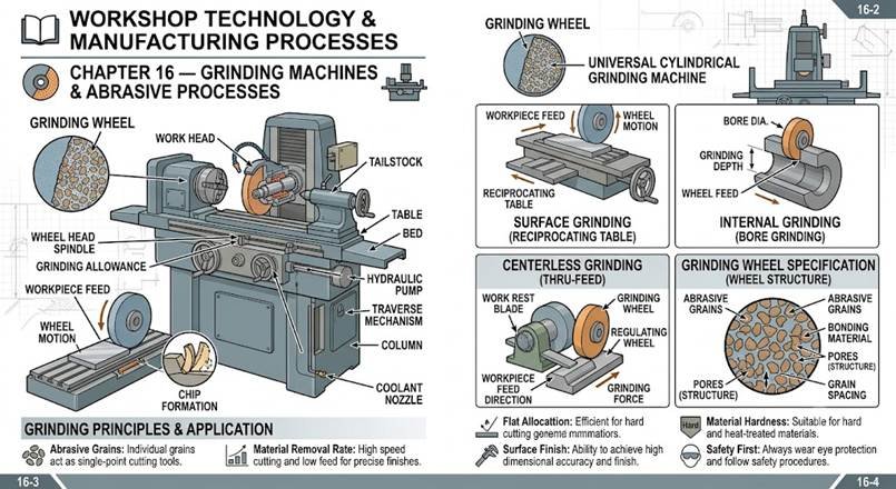
16.1 Definition of Grinding
Grinding is an abrasive machining process in which material is removed from a workpiece by the action of a large number of small, hard abrasive particles.
Unlike conventional cutting tools, a grinding wheel contains a large number of cutting points.
Key point
Grinding = Abrasive machining + large number of cutting edges
16.2 Principle of Grinding
In grinding:
- The grinding wheel rotates at high speed.
- Abrasive grains act as cutting edges.
- The grains penetrate the workpiece surface.
- Small chips are removed.
- A highly accurate and good-quality surface is produced.
Grinding is generally used for finishing operations, although it can also be used for substantial material removal.
16.3 Main Characteristics of Grinding
Grinding generally involves:
Abrasive cutting
Very high wheel speed
Very small depth of cut
Large number of cutting edges
Small chips
High surface finish
High dimensional accuracy
16.4 Abrasive
An abrasive is a hard material capable of removing material from another surface by cutting, rubbing or scratching.
Common abrasives include:
Aluminium oxide
Silicon carbide
Diamond
Cubic boron nitride
16.5 Aluminium Oxide — Al₂O₃
Aluminium oxide is commonly used for grinding:
Steels
Wrought iron
Nickel alloys
Other ferrous materials
It is commonly designated as:
A
16.6 Silicon Carbide — SiC
Silicon carbide is commonly used for:
Cast iron
Aluminium
Brass
Bronze
Carbides
Non-ferrous materials
It is commonly designated as:
C
16.7 Diamond
Diamond is an extremely hard abrasive.
It is used for:
Carbides
Ceramics
Glass
Very hard non-ferrous materials
Precision applications
Diamond is generally not preferred for grinding ordinary steels because of chemical interaction at high temperature.
16.8 Cubic Boron Nitride — CBN
CBN is a very hard synthetic abrasive.
It is particularly suitable for:
Hardened steels
Tool steels
Superalloys
16.9 Grinding Wheel
A grinding wheel consists essentially of:
- Abrasive grains
- Bond
- Pores/voids
Basic structure:
Abrasive grain + bond + pores
16.10 Functions of Abrasive Grain
The abrasive grain:
Performs the actual cutting action.
Each grain acts approximately as a small cutting edge.
16.11 Function of Bond
The bond:
Holds the abrasive grains together.
When grains become dull, appropriate wheel action allows worn grains to break away and expose fresh cutting edges.
16.12 Function of Pores
Pores provide spaces for:
Chip accommodation
Coolant passage
Air circulation
16.13 Grinding Wheel Specification
A grinding wheel specification generally indicates:
- Abrasive type
- Grain size
- Grade
- Structure
- Bond
Example:
A 46 K 5 V
The exact notation can vary with the standard/manufacturer, but the concepts remain important.
16.14 Grain Size
Grain size indicates the approximate size of abrasive particles.
Coarse grains
Used for:
High material removal
Soft materials
Rough grinding
Large contact areas
Fine grains
Used for:
Finishing
Hard materials
Small contact areas
Better surface finish
16.15 Grinding Wheel Grade
Grade indicates the strength with which abrasive grains are held by the bond.
It is NOT a direct measure of abrasive hardness.
Soft-grade wheel
The grains are released relatively easily.
Suitable for:
Hard materials
Hard-grade wheel
The grains are held more strongly.
Suitable for:
Soft materials
16.16 Important Rule
Hard workpiece → Soft grinding wheel
Soft workpiece → Hard grinding wheel
This is one of the most frequently tested grinding principles.
16.17 Wheel Structure
Structure indicates the relative spacing between abrasive grains.
Open structure
Has more space between grains.
Advantages:
Better chip clearance
Better coolant access
Lower tendency for loading
Dense/close structure
Has relatively less space between grains.
Suitable for:
Fine finishing
Stronger support of grains
16.18 Grinding Wheel Bond
The bond holds abrasive grains together.
Common bonds include:
Vitrified
Resinoid
Rubber
Shellac
Silicate
Metal
16.19 Vitrified Bond
Vitrified bonds are widely used.
Advantages:
Good rigidity
Good dimensional accuracy
Good resistance to heat
Suitable for many general grinding operations
16.20 Resinoid Bond
Resinoid bonds are made using resin.
They are known for:
High strength
Good shock resistance
High-speed applications
16.21 Rubber Bond
Rubber bonds are used where:
High elasticity is required
Thin wheels are required
Certain finishing/cut-off applications are involved
16.22 Shellac Bond
Shellac bonds can provide:
Good surface finish
Elasticity
They are used in certain finishing operations.
16.23 Dressing
Dressing is the process of removing dull grains, loading material and bond from the wheel surface to expose fresh sharp abrasive grains.
Purpose:
Restore cutting ability
Remove loading
Maintain wheel condition
16.24 Truing
Truing is the process of restoring the geometrical shape and concentricity of a grinding wheel.
Difference:
Dressing → restores cutting condition
Truing → restores geometrical form
This distinction is very important in examinations.
16.25 Wheel Loading
Wheel loading occurs when:
Workpiece material becomes embedded in the spaces between abrasive grains.
It is particularly common when grinding:
Soft
Ductile
Sticky materials
16.26 Glazing
Glazing occurs when:
Abrasive grains become dull and the wheel surface becomes relatively smooth and shiny.
The wheel loses cutting ability.
16.27 Grinding Machines
Major types include:
- Surface grinding machine
- Cylindrical grinding machine
- Internal grinding machine
- Centreless grinding machine
- Tool and cutter grinder
- Universal grinding machine
16.28 Surface Grinding
Surface grinding is used primarily to produce:
Flat and accurate surfaces.
The workpiece may be held using:
Magnetic chuck
Mechanical fixture
Clamps
16.29 Cylindrical Grinding
Cylindrical grinding is used for:
External cylindrical surfaces.
The workpiece generally rotates while the grinding wheel also rotates.
16.30 Internal Grinding
Internal grinding is used for:
Internal cylindrical surfaces or bores.
A small grinding wheel is used inside the workpiece.
16.31 Centreless Grinding
In centreless grinding, the workpiece is not held between centres.
The main components are:
- Grinding wheel
- Regulating wheel
- Work-rest blade
16.32 Principle of Centreless Grinding
The grinding wheel performs the cutting operation.
The regulating wheel:
Controls workpiece rotation
Controls longitudinal movement in through-feed grinding
The work-rest blade supports the workpiece.
16.33 Through-Feed Centreless Grinding
Used for:
Long cylindrical workpieces of uniform cross-section.
The workpiece passes continuously between the grinding wheel and regulating wheel.
16.34 In-Feed Centreless Grinding
Used for:
Workpieces having shoulders or complex profiles that cannot pass straight through.
The workpiece is fed radially into position.
16.35 End-Feed Centreless Grinding
Used for:
Tapered or similar workpieces where feeding is from one end.
16.36 Advantages of Centreless Grinding
No centre holes required
High production rate
Continuous operation possible
Suitable for mass production
Good dimensional accuracy
16.37 Grinding Wheel Speed
Grinding wheel speed is commonly expressed in:
m/s
The relationship is:
where:
= wheel peripheral speed in m/s
= wheel diameter in mm
= rpm
16.38 Important Grinding Safety
Grinding wheels operate at high speed.
Important precautions:
Inspect wheel before mounting.
Ensure correct mounting.
Use proper guards.
Use suitable eye/face protection.
Never exceed rated wheel speed.
Maintain correct work-rest clearance.
Avoid excessive pressure.
Stand safely during initial wheel run.
16.39 Ring Test
A vitrified grinding wheel is commonly subjected to a:
Ring test
before mounting to detect cracks.
A cracked wheel should never be used.
16.40 Grinding Wheel Balancing
Balancing is important because an unbalanced wheel can cause:
Vibration
Poor surface finish
Uneven wear
Reduced accuracy
Safety hazards
16.41 Grinding vs Milling
| Feature | Grinding | Milling |
| Cutting tool | Abrasive wheel | Milling cutter |
| Cutting points | Very large number | Multiple teeth |
| Material removal | Small chips | Larger chips generally |
| Main use | Finishing/precision | General machining |
| Speed | Very high | Lower than grinding wheel speed |
| Accuracy | Very high | Depends on operation |
16.42 Grinding vs Shaping
| Grinding | Shaping |
| Abrasive cutting | Single-point cutting |
| Rotating wheel | Reciprocating tool |
| Very high speed | Relatively low speed |
| Fine finish | General machining |
16.43 Important Exam Facts
Grinding → Abrasive machining
Abrasive → Cutting action
Bond → Holds grains
Pores → Chip/coolant space
Grade → Grain-holding strength
Hard workpiece → Soft wheel
Soft workpiece → Hard wheel
Dressing → Restores cutting ability
Truing → Restores geometry
Loading → Material embedded in wheel
Glazing → Dull grains
Surface grinding → Flat surfaces
Cylindrical grinding → External cylindrical surfaces
Internal grinding → Bores
Centreless grinding → No centres
CBN → Hardened steels
Diamond → Carbides/ceramics and many non-ferrous applications
Ring test → Crack detection
Q1. Grinding is primarily a:
A. Casting process
B. Abrasive machining process
C. Welding process
D. Forming process
Answer: B. Abrasive machining process
Explanation: Material is removed by abrasive grains acting as cutting edges.
Q2. A grinding wheel contains:
A. Only one cutting edge
B. Many abrasive cutting edges
C. No cutting edges
D. Only one large tooth
Answer: B. Many abrasive cutting edges
Q3. The main cutting action in grinding is performed by:
A. Bond
B. Abrasive grains
C. Pores
D. Wheel hub
Answer: B. Abrasive grains
Q4. The function of the bond in a grinding wheel is to:
A. Hold abrasive grains together
B. Perform all cutting
C. Cool the workpiece
D. Measure wheel speed
Answer: A. Hold abrasive grains together
Q5. Pores in a grinding wheel primarily provide:
A. Chip clearance and coolant space
B. Additional hardness
C. Spindle rotation
D. Workpiece support
Answer: A. Chip clearance and coolant space
Q6. Aluminium oxide is commonly designated as:
A. A
B. C
C. D
D. B
Answer: A. A
Q7. Silicon carbide is commonly designated as:
A. A
B. C
C. V
D. R
Answer: B. C
Q8. Aluminium oxide is particularly suitable for grinding:
A. Steels
B. Only glass
C. Only diamond
D. Only wood
Answer: A. Steels
Q9. Silicon carbide is commonly used for grinding:
A. Cast iron and non-ferrous materials
B. Only soft steel
C. Only rubber
D. Only wood
Answer: A. Cast iron and non-ferrous materials
Q10. CBN is particularly suitable for:
A. Hardened steels
B. Soft wood
C. Plastic only
D. Rubber only
Answer: A. Hardened steels
Q11. Diamond abrasive is commonly used for grinding:
A. Carbides and ceramics
B. Ordinary mild steel as the universal choice
C. Wood
D. Rubber
Answer: A. Carbides and ceramics
Q12. The grade of a grinding wheel indicates:
A. Strength with which grains are held
B. Grain size only
C. Wheel diameter
D. Wheel speed only
Answer: A. Strength with which grains are held
Q13. For grinding a hard material, the preferred wheel grade is generally:
A. Soft
B. Hard
C. Extra-hard in every case
D. No bond
Answer: A. Soft
Q14. For grinding a soft material, a generally suitable wheel grade is:
A. Hard
B. Soft
C. No grade
D. Liquid
Answer: A. Hard
Q15. Fine abrasive grains are generally used for:
A. Fine finishing
B. Very rough stock removal only
C. Casting
D. Welding
Answer: A. Fine finishing
Q16. Coarse abrasive grains are generally suitable for:
A. High material removal
B. Final ultra-fine finishing only
C. Measuring
D. Inspection
Answer: A. High material removal
Q17. Dressing of a grinding wheel is performed to:
A. Restore cutting ability
B. Increase workpiece diameter
C. Change machine spindle direction
D. Measure hardness
Answer: A. Restore cutting ability
Q18. Truing is primarily performed to:
A. Restore wheel geometry
B. Increase abrasive hardness
C. Reduce workpiece temperature only
D. Change grain type
Answer: A. Restore wheel geometry
Q19. Wheel loading occurs when:
A. Work material becomes embedded in the wheel
B. Abrasive grains become sharper
C. Wheel becomes perfectly balanced
D. Bond disappears completely
Answer: A. Work material becomes embedded in the wheel
Q20. Glazing of a grinding wheel is associated with:
A. Dull abrasive grains
B. Fresh sharp grains
C. Excessive pores only
D. New wheel mounting
Answer: A. Dull abrasive grains
Q21. Surface grinding is primarily used to produce:
A. Flat surfaces
B. Deep holes only
C. External threads
D. Gear teeth only
Answer: A. Flat surfaces
Q22. Cylindrical grinding is mainly used for:
A. External cylindrical surfaces
B. Flat surfaces only
C. Internal threads only
D. Square holes
Answer: A. External cylindrical surfaces
Q23. Internal grinding is used mainly for:
A. Internal cylindrical surfaces
B. External flat surfaces
C. Gear teeth only
D. Welding joints
Answer: A. Internal cylindrical surfaces
Q24. In centreless grinding, the workpiece is:
A. Not held between centres
B. Always held between two centres
C. Welded to the machine
D. Held only by a chuck
Answer: A. Not held between centres
Q25. The three major elements in centreless grinding are:
A. Grinding wheel, regulating wheel and work-rest blade
B. Chuck, tailstock and carriage
C. Drill, vice and table
D. Cutter, arbor and overarm
Answer: A. Grinding wheel, regulating wheel and work-rest blade
A. GRINDING WHEELS & SPECIFICATION — MCQs 26–45
Q26. Which of the following is NOT a basic component of a grinding wheel?
A. Abrasive grains
B. Bond
C. Pores
D. Gear teeth
Answer: D. Gear teeth
Explanation: A grinding wheel consists essentially of abrasive grains held by a bond with pores between them.
Q27. The letter indicating the abrasive type in a grinding-wheel specification is generally placed:
A. First
B. Last
C. In the middle only
D. After the wheel diameter
Answer: A. First
Q28. In the specification A 46 K 5 V, “A” commonly represents:
A. Aluminium oxide
B. Abrasive size
C. Artificial diamond
D. Aluminium alloy
Answer: A. Aluminium oxide
Q29. In the specification A 46 K 5 V, “46” represents:
A. Grain size
B. Wheel diameter
C. Wheel speed
D. Grade
Answer: A. Grain size
Q30. In the same specification, “K” generally represents:
A. Grade
B. Grain size
C. Bond
D. Diameter
Answer: A. Grade
Q31. In the specification A 46 K 5 V, “V” represents:
A. Vitrified bond
B. Very coarse grain
C. Velocity
D. Volume
Answer: A. Vitrified bond
Q32. Which grinding-wheel characteristic indicates the relative spacing of abrasive grains?
A. Structure
B. Grade
C. Diameter
D. Speed
Answer: A. Structure
Q33. A grinding wheel with more space between abrasive grains is called:
A. Open-structure wheel
B. Closed-structure wheel
C. Solid wheel
D. Dense wheel
Answer: A. Open-structure wheel
Q34. An open-structure grinding wheel is particularly useful where:
A. Chip clearance is important
B. No chips are produced
C. Only polishing is required
D. The workpiece is stationary forever
Answer: A. Chip clearance is important
Q35. A close-structure wheel contains:
A. Relatively closely spaced abrasive grains
B. No abrasive grains
C. Only pores
D. Only bond
Answer: A. Relatively closely spaced abrasive grains
Q36. Which bond is commonly used for general-purpose grinding wheels?
A. Vitrified
B. Paper
C. Wood
D. Plastic film
Answer: A. Vitrified
Q37. Vitrified bonds are made primarily from:
A. Ceramic materials
B. Rubber only
C. Shellac only
D. Steel
Answer: A. Ceramic materials
Q38. Resinoid bonds are based primarily on:
A. Synthetic resin
B. Ceramic
C. Rubber only
D. Wood
Answer: A. Synthetic resin
Q39. Resinoid wheels are particularly suitable for:
A. High-speed applications
B. Only hand filing
C. Casting
D. Welding
Answer: A. High-speed applications
Q40. Rubber-bonded grinding wheels are particularly useful where:
A. Elasticity is required
B. No flexibility is required
C. No abrasive is needed
D. Only drilling is performed
Answer: A. Elasticity is required
Q41. Shellac-bonded wheels are often used when:
A. Good surface finish is required
B. Very heavy rough machining is always required
C. No finishing is required
D. Only drilling is required
Answer: A. Good surface finish is required
Q42. Which bond generally provides high dimensional accuracy and rigidity?
A. Vitrified
B. Rubber
C. Shellac
D. Leather
Answer: A. Vitrified
Q43. The grade of a grinding wheel is mainly determined by:
A. Bond strength and holding action
B. Wheel diameter only
C. Grain colour
D. Spindle length
Answer: A. Bond strength and holding action
Q44. Increasing the grade from soft toward hard means:
A. Abrasive grains are held more strongly
B. Grain size necessarily becomes larger
C. Wheel diameter increases
D. Speed becomes zero
Answer: A. Abrasive grains are held more strongly
Q45. Which combination is generally correct?
A. Hard workpiece — soft wheel
B. Hard workpiece — hard wheel
C. Soft workpiece — soft wheel only
D. Wheel grade has no relation to workpiece hardness
Answer: A. Hard workpiece — soft wheel
B. GRINDING MACHINE TYPES — MCQs 46–60
Q46. A surface grinding machine is mainly used for:
A. Flat surfaces
B. Deep internal threads
C. Gear hobbing
D. Turning shafts
Answer: A. Flat surfaces
Q47. A cylindrical grinding machine is mainly used for:
A. External cylindrical surfaces
B. Flat surfaces only
C. T-slots
D. Keyway broaching
Answer: A. External cylindrical surfaces
Q48. An internal grinding machine is used to grind:
A. Internal surfaces/bores
B. External threads only
C. Flat plates only
D. Gear teeth only
Answer: A. Internal surfaces/bores
Q49. In cylindrical grinding, the workpiece commonly:
A. Rotates about its axis
B. Remains permanently stationary
C. Reciprocates vertically only
D. Is melted
Answer: A. Rotates about its axis
Q50. A universal cylindrical grinder can generally perform:
A. External and internal grinding operations
B. Only drilling
C. Only surface milling
D. Only welding
Answer: A. External and internal grinding operations
Q51. Centreless grinding differs from cylindrical grinding mainly because:
A. The workpiece is not supported between centres
B. The wheel does not rotate
C. No abrasive is used
D. No material is removed
Answer: A. The workpiece is not supported between centres
Q52. The regulating wheel in centreless grinding primarily controls:
A. Workpiece rotation and feed
B. Abrasive composition
C. Wheel dressing only
D. Coolant temperature only
Answer: A. Workpiece rotation and feed
Q53. The work-rest blade in centreless grinding:
A. Supports the workpiece
B. Rotates the grinding wheel
C. Dresses the wheel
D. Measures wheel speed
Answer: A. Supports the workpiece
Q54. Through-feed centreless grinding is best suited for:
A. Long cylindrical components without interruptions
B. Components with large shoulders that block through-feed
C. Square plates
D. Flat sheets only
Answer: A. Long cylindrical components without interruptions
Q55. In-feed centreless grinding is suitable for:
A. Components with shoulders or formed profiles
B. Only long uniform shafts
C. Flat plates
D. Drill bits only
Answer: A. Components with shoulders or formed profiles
Q56. End-feed centreless grinding is particularly suitable for:
A. Certain tapered workpieces
B. Flat plates
C. Square holes
D. Gear hobbing
Answer: A. Certain tapered workpieces
Q57. A major advantage of centreless grinding is:
A. High production rate
B. Requirement of centre holes
C. Very low accuracy
D. No continuous operation
Answer: A. High production rate
Q58. Centreless grinding is particularly suitable for:
A. Mass production of cylindrical components
B. Only one-off casting repair
C. Welding operations
D. Sheet-metal bending
Answer: A. Mass production of cylindrical components
Q59. A tool-and-cutter grinder is used mainly for:
A. Sharpening and grinding cutting tools
B. Welding tools
C. Casting tools
D. Measuring tools only
Answer: A. Sharpening and grinding cutting tools
Q60. Surface grinding generally provides:
A. High dimensional accuracy and good surface finish
B. Only rough surfaces
C. No dimensional control
D. Only curved surfaces
Answer: A. High dimensional accuracy and good surface finish
C. DRESSING, TRUING & GRINDING DEFECTS — MCQs 61–75
Q61. Dressing of a grinding wheel is performed to:
A. Expose fresh abrasive grains
B. Increase workpiece hardness
C. Increase workpiece diameter
D. Reduce spindle speed to zero
Answer: A. Expose fresh abrasive grains
Q62. Truing primarily restores:
A. Geometrical shape of the wheel
B. Workpiece chemical composition
C. Wheel colour
D. Coolant concentration
Answer: A. Geometrical shape of the wheel
Q63. A grinding wheel may require dressing when it becomes:
A. Loaded or dull
B. Newly mounted only
C. Smaller than the workpiece
D. Completely absent
Answer: A. Loaded or dull
Q64. Glazing is associated with:
A. Dull abrasive grains
B. Fresh sharp grains
C. Excessive chip space
D. Broken machine table
Answer: A. Dull abrasive grains
Q65. Loading is more likely when grinding:
A. Soft and ductile materials
B. Extremely brittle materials only
C. Glass only
D. Ceramics only
Answer: A. Soft and ductile materials
Q66. One common remedy for wheel loading is:
A. Proper dressing
B. Increasing workpiece hardness
C. Removing all abrasive grains
D. Stopping the spindle permanently
Answer: A. Proper dressing
Q67. Burn marks on a ground surface may result from:
A. Excessive heat generation
B. No contact between wheel and work
C. Insufficient wheel rotation in every case
D. Excessive workpiece hardness only
Answer: A. Excessive heat generation
Q68. Grinding burn can often be reduced by:
A. Proper coolant and suitable grinding parameters
B. Increasing pressure indefinitely
C. Blocking coolant flow
D. Using a cracked wheel
Answer: A. Proper coolant and suitable grinding parameters
Q69. Chatter marks on a ground surface are commonly associated with:
A. Vibration
B. Perfect wheel balance
C. No cutting action
D. Proper dressing only
Answer: A. Vibration
Q70. An unbalanced grinding wheel can cause:
A. Vibration
B. Improved finish automatically
C. Zero cutting force
D. Increased workpiece strength
Answer: A. Vibration
Q71. Dressing can help to correct:
A. Loading and glazing
B. Workpiece chemical composition
C. Machine foundation
D. Gear ratio
Answer: A. Loading and glazing
Q72. Truing is especially important when the wheel:
A. Loses its desired geometrical shape
B. Is perfectly round and balanced
C. Has no abrasive
D. Is not rotating
Answer: A. Loses its desired geometrical shape
Q73. Excessive grinding pressure can cause:
A. Excessive heat and wheel wear
B. Zero temperature
C. No material removal
D. Automatic balancing
Answer: A. Excessive heat and wheel wear
Q74. Poor grinding finish can result from:
A. Vibration, improper dressing or unsuitable parameters
B. Proper wheel selection only
C. Correct balancing only
D. Perfect coolant supply only
Answer: A. Vibration, improper dressing or unsuitable parameters
Q75. The main purpose of coolant in grinding is to:
A. Reduce heat and flush chips
B. Increase wheel cracking
C. Stop material removal
D. Harden the machine bed
Answer: A. Reduce heat and flush chips
D. GRINDING SAFETY — MCQs 76–85
Q76. Before mounting a vitrified grinding wheel, a commonly recommended inspection is:
A. Ring test
B. Tensile test
C. Compression test only
D. Charpy test
Answer: A. Ring test
Q77. A grinding wheel that fails inspection or is found cracked should be:
A. Rejected and not used
B. Used at half speed
C. Used without a guard
D. Used only for rough grinding
Answer: A. Rejected and not used
Q78. A grinding machine should be operated with:
A. Appropriate wheel guard
B. Guard removed
C. Loose workpiece
D. Damaged wheel
Answer: A. Appropriate wheel guard
Q79. The maximum permissible wheel speed should:
A. Not be exceeded
B. Always be doubled
C. Be ignored
D. Be selected randomly
Answer: A. Not be exceeded
Q80. During grinding, the operator should use:
A. Appropriate eye/face protection
B. No protection
C. Only cotton gloves near a rotating wheel
D. Loose clothing
Answer: A. Appropriate eye/face protection
Q81. The work-rest on a bench grinding machine should be:
A. Properly adjusted with a small safe clearance
B. Extremely far from the wheel
C. Touching the wheel continuously
D. Removed
Answer: A. Properly adjusted with a small safe clearance
Q82. A grinding wheel should be mounted:
A. Correctly and securely
B. Loosely
C. With damaged flanges
D. Without inspection
Answer: A. Correctly and securely
Q83. Standing directly in the plane of a newly mounted wheel during initial start-up should be:
A. Avoided
B. Required
C. Done without protection
D. Done with maximum pressure
Answer: A. Avoided
Q84. A grinding wheel should be allowed to reach proper operating condition before:
A. Applying the workpiece
B. Mounting the wheel
C. Inspecting the guard
D. Switching on coolant
Answer: A. Applying the workpiece
Q85. The most important reason for grinding-wheel guards is:
A. Protection from wheel fragments and contact hazards
B. Increasing workpiece hardness
C. Increasing grain size
D. Reducing machine weight
Answer: A. Protection from wheel fragments and contact hazards
E. NUMERICAL & CONCEPTUAL MCQs — 86–100
Q86. A grinding wheel of diameter 200 mm rotates at 3000 rpm. Its peripheral speed is approximately:
A. 15.7 m/s
B. 31.4 m/s
C. 62.8 m/s
D. 100 m/s
Answer: B. 31.4 m/s
Q87. A 300 mm diameter wheel rotates at 2000 rpm. Its peripheral speed is approximately:
A. 15.7 m/s
B. 31.4 m/s
C. 62.8 m/s
D. 94.2 m/s
Answer: B. 31.4 m/s
Q88. A grinding wheel has a diameter of 400 mm and rotates at 1500 rpm. Peripheral speed is approximately:
A. 15.7 m/s
B. 31.4 m/s
C. 50 m/s
D. 75 m/s
Answer: B. 31.4 m/s
Q89. If grinding-wheel diameter remains constant and rpm is doubled, peripheral speed:
A. Doubles
B. Halves
C. Remains unchanged
D. Becomes one-fourth
Answer: A. Doubles
Q90. If wheel diameter is doubled at constant rpm, peripheral speed:
A. Doubles
B. Halves
C. Remains constant
D. Becomes zero
Answer: A. Doubles
Q91. A 250 mm grinding wheel rotates at 2400 rpm. Peripheral speed is approximately:
A. 10 m/s
B. 20 m/s
C. 31.4 m/s
D. 50 m/s
Answer: B. 31.4 m/s
Note: The closest exact value is 31.4 m/s.
Q92. A grinding wheel has a peripheral speed of 25 m/s and diameter 200 mm. Its approximate rpm is:
A. 1194 rpm
B. 2387 rpm
C. 4775 rpm
D. 7500 rpm
Answer: B. 2387 rpm
Q93. Which abrasive is generally preferred for grinding hardened steel?
A. CBN
B. Wood
C. Rubber
D. Graphite
Answer: A. CBN
Q94. Which abrasive is commonly preferred for grinding aluminium oxide ceramics and many carbide applications?
A. Diamond
B. Aluminium oxide only
C. Wood
D. Cast iron
Answer: A. Diamond
Q95. A soft-grade wheel is selected for hard material mainly because:
A. Dull grains can break away more readily and expose fresh grains
B. Hard materials require no cutting
C. Soft wheels contain no abrasive
D. It eliminates all heat
Answer: A. Dull grains can break away more readily and expose fresh grains
Q96. In centreless grinding, the regulating wheel generally has:
A. Lower speed than the grinding wheel
B. Higher speed than the grinding wheel
C. Exactly the same function as the grinding wheel
D. No rotation
Answer: A. Lower speed than the grinding wheel
Q97. The regulating wheel in centreless grinding controls the:
A. Workpiece rotational speed and feed
B. Abrasive grain size
C. Wheel bond
D. Wheel diameter
Answer: A. Workpiece rotational speed and feed
Q98. Which process is particularly suitable for producing large quantities of identical cylindrical components?
A. Through-feed centreless grinding
B. Manual filing
C. Hand scraping
D. Shaping only
Answer: A. Through-feed centreless grinding
Q99. Grinding is capable of achieving high accuracy mainly because:
A. Very small material removal can be controlled
B. The workpiece is always melted
C. The wheel has only one tooth
D. No cutting occurs
Answer: A. Very small material removal can be controlled
Q100. Which combination is correct?
A. Dressing — cutting ability; Truing — geometrical accuracy
B. Dressing — workpiece heating; Truing — coolant supply
C. Dressing — gear cutting; Truing — drilling
D. Dressing — welding; Truing — casting
Answer: A. Dressing — cutting ability; Truing — geometrical accuracy
CHAPTER 16 — COMPLETE REVISION TABLE
| Topic | Important Point |
| Grinding | Abrasive machining |
| Abrasive | Performs cutting |
| Bond | Holds grains |
| Pores | Chip/coolant space |
| Aluminium oxide | A |
| Silicon carbide | C |
| CBN | Hardened steels |
| Diamond | Carbides/ceramics |
| Grade | Grain-holding strength |
| Structure | Grain spacing |
| Hard workpiece | Soft wheel |
| Soft workpiece | Hard wheel |
| Dressing | Restores cutting ability |
| Truing | Restores geometry |
| Loading | Material embedded in wheel |
| Glazing | Dull grains |
| Surface grinding | Flat surfaces |
| Cylindrical grinding | External cylindrical surfaces |
| Internal grinding | Internal surfaces |
| Centreless grinding | No centres |
| Through-feed | Long uniform components |
| In-feed | Shouldered/profiled components |
| Regulating wheel | Controls work rotation/feed |
| Work-rest blade | Supports work |
| Ring test | Crack detection |
| Wheel guard | Safety |
| Wheel speed | Do not exceed rated speed |
CHAPTER 17 — DRILLING, BORING, REAMING & TAPPING
17.1 Definition of Drilling
Drilling is a machining process used to produce a circular hole in a solid workpiece by means of a rotating multi-point cutting tool called a drill.
Key point
Drilling = Producing a new circular hole using a rotating drill.
17.2 Principle of Drilling
During drilling:
- The drill rotates.
- The drill is fed axially into the workpiece.
- Cutting edges remove material.
- Chips travel through the drill flutes.
- A cylindrical hole is produced.
A conventional twist drill normally has two main cutting lips.
17.3 Main Applications of Drilling
Drilling is used to:
Produce new holes
Prepare holes for bolts
Prepare holes for tapping
Prepare holes for reaming
Produce holes for shafts and pins
Produce holes for assembly
17.4 Drilling Machines
Important types include:
- Portable drilling machine
- Bench drilling machine
- Pillar drilling machine
- Sensitive drilling machine
- Radial drilling machine
- Gang drilling machine
- Multi-spindle drilling machine
- CNC drilling machine
17.5 Portable Drilling Machine
A portable drill is:
Lightweight
Easily movable
Suitable for field work
Used for relatively small holes
It is particularly useful when the workpiece is:
Too large or inconvenient to move to a fixed machine.
17.6 Sensitive Drilling Machine
A sensitive drilling machine is designed for:
Small holes
Light cutting operations
High-speed drilling
Hand-controlled feed
The operator can sense the drilling pressure through the feed mechanism.
17.7 Bench Drilling Machine
A bench drill is mounted on a:
Workbench or bench.
It is commonly used for:
Small components
Small holes
Light-duty drilling
17.8 Pillar Drilling Machine
A pillar drilling machine has a rigid vertical column and is used for:
Larger workpieces
More accurate drilling
Medium-duty operations
17.9 Radial Drilling Machine
A radial drilling machine has a:
Radial arm and drill head.
Its major advantage is that the drill head can be positioned over different locations of a large workpiece without moving the workpiece itself.
It is especially suitable for:
Large and heavy workpieces.
17.10 Gang Drilling Machine
A gang drilling machine has:
Several drilling heads arranged in a row.
Different operations can be performed successively at different stations.
For example:
Drilling → Counterboring → Reaming → Tapping
17.11 Multi-Spindle Drilling Machine
A multi-spindle machine has:
Multiple spindles.
It is useful for:
Simultaneous drilling of several holes
Mass production
High productivity
17.12 Twist Drill
The most commonly used drill is the:
Twist drill.
A twist drill generally has:
Two cutting lips
Two helical flutes
Web
Shank
Point
17.13 Drill Shank
The shank is the portion used to:
Hold the drill in the machine spindle or chuck.
Two common types are:
Straight shank
Taper shank
17.14 Straight-Shank Drill
A straight-shank drill has a cylindrical shank.
It is commonly held in:
Drill chuck.
17.15 Taper-Shank Drill
A taper-shank drill has a tapered shank.
It can be directly mounted in:
A matching tapered spindle/socket.
17.16 Drill Flutes
The flutes are helical grooves running along the drill.
Functions:
Provide chip space
Form cutting edges
Allow coolant/lubricant access
Help remove chips
17.17 Drill Point
The point is the cutting end of the drill.
It includes:
Cutting lips
Chisel edge
Point geometry
17.18 Chisel Edge
The chisel edge is located at the centre of a conventional twist drill.
It:
Extrudes/ploughs material rather than cutting efficiently
Requires considerable thrust
Produces relatively poor cutting action at the centre
17.19 Drill Web
The web is the central portion between the flutes.
It provides:
Strength to the drill.
17.20 Point Angle
The included point angle of a conventional twist drill for general-purpose drilling of many steels is approximately:
However, the optimum point angle depends on the work material and application.
17.21 Helix Angle
The helix angle is associated with the inclination of the drill flute relative to the drill axis.
It affects:
Chip removal
Cutting action
Drill strength
17.22 Drill Materials
Common drill materials include:
High-speed steel (HSS)
Carbides
Cobalt high-speed steel
Carbide-tipped materials
HSS is widely used because of its:
Toughness
Heat resistance
Good cutting performance
17.23 Drilling Speed
The cutting speed for drilling is generally calculated from the drill diameter and spindle speed:
where:
= cutting speed in m/min
= drill diameter in mm
= spindle speed in rpm
17.24 Spindle Speed
Rearranging the formula:
17.25 Drilling Feed
Feed in drilling is commonly expressed as:
mm/rev
The feed rate is:
where:
= feed in mm/rev
= rpm
= feed rate in mm/min
17.26 Drilling Time
Approximate drilling time can be calculated as:
where represents the effective drilling length.
In practical calculations, approach and breakthrough allowances may also need to be considered.
17.27 Counterboring
Counterboring is the operation of enlarging the upper portion of an existing hole to produce a cylindrical recess.
It is commonly used to:
Accommodate a socket-head cap screw or bolt head.
17.28 Countersinking
Countersinking produces a conical enlargement at the entrance of a hole.
It is commonly used to:
Accommodate a countersunk-head screw.
17.29 Spot Facing
Spot facing produces:
A flat seating surface around a hole.
It is particularly useful when the original surface is:
Rough
Uneven
Cast
Forged
17.30 Boring
Boring is the process of enlarging and/or improving the accuracy of an existing hole using a single-point or suitable boring tool.
Important distinction:
Drilling → creates a new hole
Boring → enlarges an existing hole
17.31 Reaming
Reaming is a finishing operation used to slightly enlarge an existing hole and improve its dimensional accuracy and surface finish.
A reamer removes:
A small amount of material.
17.32 Reamer
A reamer is a:
Multi-edge finishing tool.
It is not normally used for making a hole from solid material.
17.33 Types of Reamers
Common types:
Hand reamer
Machine reamer
Adjustable reamer
Expansion reamer
Taper reamer
17.34 Tapping
Tapping is the process of producing internal threads in a hole using a tap.
The hole is first drilled to an appropriate tapping size.
17.35 Tap
A tap is a:
Thread-cutting tool used to produce internal threads.
17.36 Types of Hand Taps
A traditional hand-tapping set commonly includes:
- Taper tap
- Second/intermediate tap
- Plug/bottoming tap
17.37 Taper Tap
The taper tap has a relatively long chamfer.
It is generally used:
First in hand tapping.
17.38 Second Tap
The second tap has an intermediate chamfer.
It is used:
After the taper tap.
17.39 Bottoming/Plug Tap
A bottoming tap is used when threads are required:
Close to the bottom of a blind hole.
17.40 Blind Hole
A blind hole:
Does not pass completely through the workpiece.
17.41 Through Hole
A through hole:
Passes completely through the workpiece.
17.42 Tapping Drill Size
For a simple metric approximation:
Example:
For M10 × 1.5:
So the approximate tap-drill size is:
8.5 mm
Actual recommended sizes should follow the relevant standard and thread percentage requirement.
17.43 Drilling Defects
Common drilling problems include:
Oversized holes
Oversized/undersized or inaccurate holes
Rough surface
Chipped cutting edges
Drill wandering
Excessive burrs
Poor chip evacuation
Drill breakage
17.44 Drill Wandering
Drill wandering may result from:
Poor centering
Improper drill point
Uneven workpiece surface
Excessive clearance or incorrect geometry
Improper setup
17.45 Burr Formation
Burrs are commonly produced:
At the breakthrough side of a drilled hole.
Proper support, tooling and cutting parameters can reduce burr formation.
17.46 Important Comparison
| Operation | Main Purpose |
| Drilling | Produce new hole |
| Boring | Enlarge existing hole |
| Reaming | Improve size/finish |
| Counterboring | Cylindrical recess |
| Countersinking | Conical recess |
| Spot facing | Flat seating surface |
| Tapping | Internal thread |
Q1. Drilling is primarily used to:
A. Produce a new circular hole
B. Produce external threads
C. Grind a surface
D. Produce gear teeth
Answer: A. Produce a new circular hole
Explanation: Drilling removes material from a solid workpiece to create a hole.
Q2. The commonly used tool for drilling is:
A. Twist drill
B. Reamer
C. Tap
D. Broach
Answer: A. Twist drill
Q3. A conventional twist drill is generally a:
A. Two-lip cutting tool
B. Single-point tool
C. Grinding wheel
D. Forming tool without cutting edges
Answer: A. Two-lip cutting tool
Q4. The flutes of a twist drill are used primarily for:
A. Chip removal
B. Holding the workpiece
C. Measuring hole diameter
D. Producing coolant
Answer: A. Chip removal
Q5. The shank of a drill is used to:
A. Hold the drill
B. Remove chips
C. Cut the hole directly
D. Measure the hole
Answer: A. Hold the drill
Q6. A straight-shank drill is commonly held in a:
A. Drill chuck
B. Lathe tailstock only
C. Magnetic chuck
D. Dividing head
Answer: A. Drill chuck
Q7. A taper-shank drill can be mounted in:
A. A matching tapered spindle/socket
B. A flat table only
C. A machine vice
D. A surface plate
Answer: A. A matching tapered spindle/socket
Q8. The web of a twist drill provides:
A. Strength to the drill
B. Coolant only
C. Workpiece support
D. Thread cutting
Answer: A. Strength to the drill
Q9. The chisel edge of a twist drill is located:
A. Near the centre of the drill point
B. At the shank end
C. At the top of the flute only
D. On the machine table
Answer: A. Near the centre of the drill point
Q10. The conventional point angle of a general-purpose twist drill is approximately:
A. 60°
B. 90°
C. 118°
D. 180°
Answer: C. 118°
Q11. A radial drilling machine is particularly suitable for:
A. Large and heavy workpieces
B. Very small watch components only
C. Grinding operations
D. Gear hobbing
Answer: A. Large and heavy workpieces
Q12. The major advantage of a radial drilling machine is:
A. Drill head can be positioned over different locations of a large workpiece
B. It cannot move
C. It uses no spindle
D. It cannot drill large holes
Answer: A. Drill head can be positioned over different locations of a large workpiece
Q13. A gang drilling machine has:
A. Several drilling stations/heads
B. Only one spindle
C. No table
D. Only a grinding wheel
Answer: A. Several drilling stations/heads
Q14. A multi-spindle drilling machine is mainly used to:
A. Drill multiple holes simultaneously or efficiently
B. Perform only grinding
C. Cut external threads
D. Perform casting
Answer: A. Drill multiple holes simultaneously or efficiently
Q15. A sensitive drilling machine is particularly suitable for:
A. Small holes and light work
B. Very large castings only
C. Heavy planing
D. Gear grinding
Answer: A. Small holes and light work
Q16. The cutting speed in drilling is given by:
A.
B.
C.
D.
Answer: A.
Q17. The feed rate in drilling, when feed is mm/rev and spindle speed is rpm, is:
A.
B.
C.
D.
Answer: B.
Q18. Boring is used to:
A. Enlarge an existing hole
B. Create a hole from solid material only
C. Produce external threads
D. Grind a flat surface
Answer: A. Enlarge an existing hole
Q19. Reaming is primarily a:
A. Finishing operation
B. Rough casting operation
C. Welding operation
D. Forging operation
Answer: A. Finishing operation
Q20. Compared with drilling, reaming generally removes:
A. A small amount of material
B. A very large amount
C. No material
D. The entire workpiece
Answer: A. A small amount of material
Q21. Counterboring produces a:
A. Cylindrical recess
B. Conical recess
C. Thread
D. Square hole
Answer: A. Cylindrical recess
Q22. Countersinking produces a:
A. Conical recess
B. Cylindrical recess
C. Keyway
D. Flat slot
Answer: A. Conical recess
Q23. Spot facing produces:
A. A flat seating surface around a hole
B. An internal thread
C. A conical hole
D. A gear tooth
Answer: A. A flat seating surface around a hole
Q24. Tapping is used to produce:
A. Internal threads
B. External threads
C. Flat surfaces
D. Gear teeth
Answer: A. Internal threads
Q25. Which sequence is generally correct for producing an accurate threaded hole?
A. Drill → ream/prepare as required → tap
B. Tap → drill → grind
C. Grind → drill → tap
D. Countersink → weld → tap
Answer: A. Drill → ream/prepare as required → tap
A. DRILL NOMENCLATURE & GEOMETRY — Q26–40
Q26. The angle between the two cutting lips of a standard twist drill is approximately:
A. 60°
B. 90°
C. 118°
D. 150°
Answer: C. 118°
Explanation: A standard general-purpose twist drill commonly uses a point angle of about 118°.
Q27. The chisel edge of a twist drill mainly produces:
A. Efficient shearing
B. Ploughing action
C. Grinding action
D. Thread cutting
Answer: B. Ploughing action
Explanation: The chisel edge has an unfavourable cutting geometry and mainly pushes/ploughs material at the centre.
Q28. The main function of drill flutes is:
A. Chip removal
B. Work holding
C. Measuring depth
D. Increasing workpiece hardness
Answer: A. Chip removal
Explanation: The helical flutes provide space for chips and assist their evacuation.
Q29. The web of a twist drill is located:
A. Between the flutes
B. At the extreme end of the shank
C. Outside the workpiece
D. On the machine table
Answer: A. Between the flutes
Q30. Increasing the web thickness of a drill generally:
A. Increases drill strength
B. Eliminates all thrust
C. Removes the flutes
D. Makes the drill flexible
Answer: A. Increases drill strength
Explanation: A thicker web provides greater core strength but can increase thrust unless appropriate geometry is used.
Q31. The lip clearance angle of a drill is provided mainly to:
A. Prevent rubbing of the flank against the hole surface
B. Increase drill diameter
C. Hold the drill in the chuck
D. Increase workpiece hardness
Answer: A. Prevent rubbing of the flank against the hole surface
Q32. The helix of a twist drill mainly assists:
A. Chip evacuation
B. Workpiece clamping
C. Measurement
D. Grinding-wheel balancing
Answer: A. Chip evacuation
Q33. A drill with a larger helix angle is generally useful for:
A. Soft and ductile materials
B. Very brittle materials only
C. Concrete only
D. Glass only
Answer: A. Soft and ductile materials
Explanation: Higher helix drills generally provide better chip evacuation for ductile materials.
Q34. A low-helix drill is generally suitable for:
A. Hard and brittle materials
B. Soft plastics only
C. Rubber only
D. Wood only
Answer: A. Hard and brittle materials
Q35. The drill point is the:
A. Cutting end of the drill
B. Holding end of the drill
C. Machine spindle
D. Work-rest
Answer: A. Cutting end of the drill
Q36. The drill margin primarily helps to:
A. Guide the drill in the hole
B. Remove the entire chip
C. Hold the drill in the chuck
D. Measure spindle speed
Answer: A. Guide the drill in the hole
Q37. The cutting lips of a twist drill are formed at the intersection of:
A. Flank and face
B. Shank and web
C. Margin and shank
D. Web and shank only
Answer: A. Flank and face
Q38. The land of a twist drill is the:
A. Surface between the flute and margin
B. Central web only
C. Shank
D. Point angle
Answer: A. Surface between the flute and margin
Q39. The margin of a drill provides:
A. Guidance and support
B. Thread cutting
C. Workpiece clamping
D. Coolant generation
Answer: A. Guidance and support
Q40. A twist drill is called a multi-point cutting tool because:
A. It has more than one cutting edge
B. It has no cutting edge
C. It has one cutting edge only
D. It performs only forming
Answer: A. It has more than one cutting edge
B. DRILL MATERIALS & MACHINE SELECTION — Q41–55
Q41. HSS stands for:
A. High Speed Steel
B. High Strength Shaft
C. Hard Surface Steel
D. Heat Stabilized System
Answer: A. High Speed Steel
Q42. HSS drills are widely used because they have:
A. Good toughness and hot hardness
B. No hardness
C. No wear resistance
D. No cutting capability
Answer: A. Good toughness and hot hardness
Q43. Carbide drills are particularly advantageous for:
A. High-speed machining
B. Hand filing
C. Wood carving only
D. Welding
Answer: A. High-speed machining
Q44. Compared with HSS, carbide is generally:
A. Harder and more wear resistant but more brittle
B. Softer and more ductile
C. Less heat resistant
D. Completely flexible
Answer: A. Harder and more wear resistant but more brittle
Q45. A bench drilling machine is generally used for:
A. Small and medium-sized components
B. Huge structures only
C. Rolling mills
D. Forging only
Answer: A. Small and medium-sized components
Q46. A pillar drilling machine generally provides:
A. Greater rigidity than a small bench drill
B. No spindle movement
C. Only hand filing
D. No feed mechanism
Answer: A. Greater rigidity than a small bench drill
Q47. The radial drilling machine is especially useful when:
A. The workpiece is large and heavy
B. The workpiece is extremely small only
C. No positioning is required
D. Only tapping is performed
Answer: A. The workpiece is large and heavy
Q48. In a radial drilling machine, the radial arm allows:
A. Positioning of the drill head
B. Rotation of the workpiece only
C. Grinding of the drill
D. Measurement of diameter
Answer: A. Positioning of the drill head
Q49. A portable drilling machine is advantageous when:
A. The workpiece cannot conveniently be moved to a fixed drill
B. Extremely high precision is always required
C. Only automatic production is required
D. No drilling is required
Answer: A. The workpiece cannot conveniently be moved to a fixed drill
Q50. A sensitive drilling machine is primarily designed for:
A. Small-diameter holes
B. Large forgings only
C. Heavy milling
D. Grinding
Answer: A. Small-diameter holes
Q51. A gang drilling machine is useful when:
A. Several successive drilling operations are required
B. Only one operation is ever required
C. No hole is required
D. Only grinding is performed
Answer: A. Several successive drilling operations are required
Q52. A multi-spindle drilling machine is particularly suitable for:
A. Mass production
B. One-off artistic work only
C. Manual filing
D. Casting
Answer: A. Mass production
Q53. The primary purpose of a drill chuck is to:
A. Hold a drill securely
B. Produce threads
C. Grind the drill
D. Support a grinding wheel
Answer: A. Hold a drill securely
Q54. A taper-shank drill is advantageous because:
A. It can be mounted in a matching tapered spindle/socket
B. It cannot transmit torque
C. It requires no spindle
D. It is used only for grinding
Answer: A. It can be mounted in a matching tapered spindle/socket
Q55. A drill drift is commonly used for:
A. Removing a taper-shank drill from its socket
B. Sharpening a drill point
C. Measuring hole depth
D. Cutting threads
Answer: A. Removing a taper-shank drill from its socket
C. DRILLING PARAMETERS & NUMERICALS — Q56–70
Q56. The cutting-speed formula for drilling is:
A.
B.
C.
D.
Answer: A.
Q57. In the drilling-speed formula, D is normally expressed in:
A. mm
B. cm only
C. m only
D. inches only
Answer: A. mm
Q58. If drill diameter increases while cutting speed remains constant, spindle speed should:
A. Decrease
B. Increase
C. Remain necessarily unchanged
D. Become infinite
Answer: A. Decrease
Explanation:
Therefore, is inversely proportional to at constant cutting speed.
Q59. A 20 mm drill runs at 1000 rpm. The approximate cutting speed is:
A. 31.4 m/min
B. 62.8 m/min
C. 100 m/min
D. 200 m/min
Answer: B. 62.8 m/min
Q60. A 10 mm drill runs at 1000 rpm. Cutting speed is approximately:
A. 15.7 m/min
B. 31.4 m/min
C. 62.8 m/min
D. 100 m/min
Answer: B. 31.4 m/min
Q61. A 50 mm drill operates at 400 rpm. Cutting speed is approximately:
A. 31.4 m/min
B. 62.8 m/min
C. 100 m/min
D. 125.6 m/min
Answer: A. 62.8 m/min
Q62. If a 25 mm drill operates at 800 rpm, its cutting speed is approximately:
A. 31.4 m/min
B. 62.8 m/min
C. 75 m/min
D. 100 m/min
Answer: B. 62.8 m/min
Q63. A drill has a cutting speed of 30 m/min and diameter 10 mm. Approximate spindle speed is:
A. 477 rpm
B. 955 rpm
C. 1910 rpm
D. 3000 rpm
Answer: C. 955 rpm
Correction: The correct option is B. 955 rpm.
Q64. If feed is 0.2 mm/rev and spindle speed is 1000 rpm, feed rate is:
A. 20 mm/min
B. 100 mm/min
C. 200 mm/min
D. 500 mm/min
Answer: C. 200 mm/min
Q65. If feed is 0.1 mm/rev and spindle speed is 1500 rpm, feed rate is:
A. 100 mm/min
B. 150 mm/min
C. 300 mm/min
D. 1500 mm/min
Answer: B. 150 mm/min
Q66. If spindle speed is doubled while feed per revolution remains constant, feed rate:
A. Doubles
B. Halves
C. Remains unchanged
D. Becomes zero
Answer: A. Doubles
Q67. Drilling time is approximately determined from:
A. Drilling length ÷ feed rate
B. Drill diameter × speed
C. Feed ÷ speed
D. Diameter + speed
Answer: A. Drilling length ÷ feed rate
Q68. A hole requires an effective drilling length of 40 mm. If feed rate is 100 mm/min, approximate drilling time is:
A. 0.2 min
B. 0.4 min
C. 2.5 min
D. 4 min
Answer: B. 0.4 min
Q69. If the feed per revolution is increased while all other conditions remain constant, material removal rate generally:
A. Increases
B. Decreases to zero
C. Remains necessarily unchanged
D. Becomes negative
Answer: A. Increases
Q70. Excessive feed during drilling may result in:
A. Higher thrust and possible drill failure
B. Zero cutting force
C. No chips
D. Automatic improvement in accuracy
Answer: A. Higher thrust and possible drill failure
D. BORING, REAMING & HOLE-FINISHING OPERATIONS — Q71–82
Q71. Boring is normally performed on:
A. An existing hole
B. A solid surface without a hole
C. A grinding wheel
D. A welding electrode
Answer: A. An existing hole
Q72. Boring can be used to improve:
A. Hole size and alignment
B. Only external surface colour
C. Workpiece weight
D. Casting temperature
Answer: A. Hole size and alignment
Q73. A conventional boring operation commonly uses:
A. A single-point cutting tool
B. A grinding wheel only
C. A twist drill only
D. A tap only
Answer: A. A single-point cutting tool
Q74. Reaming is mainly performed to obtain:
A. Better dimensional accuracy and surface finish
B. A completely new large hole
C. External threads
D. A casting cavity
Answer: A. Better dimensional accuracy and surface finish
Q75. A reamer generally removes:
A. A small amount of material
B. The entire workpiece
C. No material
D. More material than rough drilling in normal use
Answer: A. A small amount of material
Q76. A reamer should normally be used after:
A. A hole has already been produced close to the required size
B. The workpiece has been melted
C. The surface has been welded
D. No hole exists
Answer: A. A hole has already been produced close to the required size
Q77. A hand reamer is operated primarily by:
A. Hand rotation
B. Grinding-wheel rotation
C. Lathe chuck only
D. Welding current
Answer: A. Hand rotation
Q78. A machine reamer is designed to be used:
A. With a machine tool
B. Only by hammering
C. Only by filing
D. As a drill chuck
Answer: A. With a machine tool
Q79. An adjustable reamer allows:
A. Limited adjustment of its effective diameter
B. Unlimited enlargement of any hole
C. Thread cutting only
D. Welding
Answer: A. Limited adjustment of its effective diameter
Q80. Counterboring produces:
A. A cylindrical recess
B. A conical recess
C. An external thread
D. A flat plate
Answer: A. A cylindrical recess
Q81. Countersinking produces:
A. A conical recess
B. A cylindrical recess
C. A square recess
D. A thread
Answer: A. A conical recess
Q82. Spot facing is performed to:
A. Provide a flat seating surface
B. Produce a helical thread
C. Reduce spindle speed
D. Produce external cylindrical surfaces
Answer: A. Provide a flat seating surface
E. TAPS & THREADING — Q83–95
Q83. Tapping is the operation of producing:
A. Internal threads
B. External threads
C. Flat surfaces
D. Gear teeth
Answer: A. Internal threads
Q84. The tool used for tapping is called a:
A. Tap
B. Die
C. Reamer
D. Broach
Answer: A. Tap
Q85. A die is generally used for producing:
A. External threads
B. Internal threads
C. Holes
D. Flat surfaces
Answer: A. External threads
Q86. The first tap in a conventional hand-tapping set is generally:
A. Taper tap
B. Bottoming tap
C. Plug tap
D. Machine reamer
Answer: A. Taper tap
Q87. A taper tap has:
A. A relatively long chamfer
B. No chamfer
C. Only one cutting edge
D. A grinding wheel
Answer: A. A relatively long chamfer
Q88. A bottoming tap is especially useful for:
A. Threads near the bottom of a blind hole
B. Cutting external threads
C. Grinding shafts
D. Drilling large holes
Answer: A. Threads near the bottom of a blind hole
Q89. A blind hole:
A. Does not pass completely through the workpiece
B. Always passes through the workpiece
C. Has no bottom
D. Is always threaded
Answer: A. Does not pass completely through the workpiece
Q90. A through hole:
A. Passes completely through the workpiece
B. Has a closed bottom
C. Is always tapered
D. Is always threaded
Answer: A. Passes completely through the workpiece
Q91. For an M10 × 1.5 thread, an approximate tap-drill diameter is:
A. 6.5 mm
B. 8.5 mm
C. 10.0 mm
D. 11.5 mm
Answer: B. 8.5 mm
Q92. For an M8 × 1.25 thread, the approximate tap-drill size is:
A. 5.75 mm
B. 6.75 mm
C. 8.0 mm
D. 9.25 mm
Answer: B. 6.75 mm
Q93. For an M12 × 1.75 thread, the approximate tap-drill size is:
A. 8.5 mm
B. 10.25 mm
C. 12 mm
D. 13.75 mm
Answer: B. 10.25 mm
Q94. The main purpose of drilling a tapping hole before tapping is to:
A. Provide the required space for the thread
B. Make the hole completely solid
C. Eliminate all cutting
D. Increase the major diameter
Answer: A. Provide the required space for the thread
Q95. During hand tapping, reversing the tap periodically is commonly done to:
A. Break and clear chips
B. Increase hole diameter indefinitely
C. Remove the machine spindle
D. Reduce thread depth to zero
Answer: A. Break and clear chips
F. DRILLING DEFECTS & TROUBLESHOOTING — Q96–100
Q96. An oversized drilled hole may result from:
A. Improper drill geometry or runout
B. Perfect alignment only
C. Correct setup only
D. Proper sharpening only
Answer: A. Improper drill geometry or runout
Q97. Drill wandering at the start of drilling can be reduced by:
A. Providing a proper starting location/spot
B. Increasing runout
C. Using a damaged drill
D. Removing work support
Answer: A. Providing a proper starting location/spot
Q98. Excessive burr formation commonly occurs:
A. At breakthrough of the drill
B. Only at the drill shank
C. On the machine base
D. Inside the spindle bearing
Answer: A. At breakthrough of the drill
Q99. Poor chip evacuation during drilling can cause:
A. Drill overheating and possible breakage
B. Automatic improvement in finish
C. Zero cutting force
D. Reduced chip formation
Answer: A. Drill overheating and possible breakage
Q100. Which sequence correctly matches the operation with its purpose?
A. Drilling—new hole; Boring—enlarge existing hole; Reaming—finish hole; Tapping—internal thread
B. Drilling—external thread; Boring—welding; Reaming—casting; Tapping—grinding
C. Drilling—flat surface; Boring—external thread; Reaming—casting; Tapping—turning
D. Drilling—grinding; Boring—forming; Reaming—welding; Tapping—milling
Answer: A. Drilling—new hole; Boring—enlarge existing hole; Reaming—finish hole; Tapping—internal thread
CHAPTER 17 QUICK REVISION
| Operation | Purpose |
| Drilling | Produces a new hole |
| Boring | Enlarges/improves existing hole |
| Reaming | Finishing and improving accuracy |
| Counterboring | Cylindrical recess |
| Countersinking | Conical recess |
| Spot facing | Flat seating surface |
| Tapping | Internal threads |
| Die threading | External threads |
| Taper tap | First hand tap |
| Bottoming tap | Threads near blind-hole bottom |
| Twist drill | Common drilling tool |
| HSS | High-speed steel |
| Radial drill | Large/heavy workpieces |
| Gang drill | Successive operations |
| Multi-spindle drill | Multiple holes/high production |
| 118° | Typical general-purpose drill point angle |
| Flutes | Chip evacuation |
| Web | Drill strength |
| Margin | Guidance |
| Chisel edge | Ploughing action |
Top of Form
Bottom of Form
CHAPTER 18 — LATHE MACHINE & TURNING OPERATIONS
18.1 Definition of Lathe
A lathe is a machine tool in which the workpiece is rotated about its axis while a cutting tool is fed against it to remove material.
Simple definition
Lathe = Rotating workpiece + stationary/fed cutting tool
The main purpose of a lathe is to produce:
Cylindrical surfaces
Conical surfaces
Threads
Grooves
Shoulders
End faces
Holes
Special profiles
18.2 Principle of Lathe
The basic working principle is:
- The workpiece is securely mounted.
- The workpiece rotates.
- The cutting tool is mounted on the tool post.
- The tool is given controlled feed.
- Material is removed in the form of chips.
The primary cutting motion is provided by the rotating workpiece.
18.3 Main Parts of a Centre Lathe
The major parts are:
- Bed
- Headstock
- Tailstock
- Carriage
- Lead screw
- Feed rod
- Tool post
- Apron
- Chuck
- Cross-slide
- Compound rest
18.4 Lathe Bed
The bed is the main supporting structure of the lathe.
It supports:
Headstock
Tailstock
Carriage
The bed is generally made from:
Cast iron or suitable cast material.
Functions
Provides rigidity
Maintains alignment
Supports major components
Absorbs vibration
18.5 Guideways
Guideways are provided on the lathe bed to guide:
Carriage
Tailstock
They ensure accurate movement parallel to the spindle axis.
18.6 Headstock
The headstock is mounted at the:
Left-hand end of the lathe bed in a conventional centre lathe.
It contains:
Main spindle
Bearings
Speed-changing mechanism
Gears/pulleys
Work-holding arrangements
18.7 Main Spindle
The spindle:
Rotates the workpiece
Transmits power
Carries the chuck or other work-holding device
The spindle is one of the most important rotating components of the lathe.
18.8 Chuck
A chuck is a work-holding device.
It is used to:
Hold and rotate the workpiece.
Common types include:
Three-jaw chuck
Four-jaw independent chuck
Collet chuck
Magnetic chuck in specialized applications
18.9 Three-Jaw Chuck
The three-jaw chuck has:
Three jaws that move simultaneously.
It is also called:
Self-centering chuck.
It is particularly suitable for:
Round work
Hexagonal work
Regular-shaped components
18.10 Four-Jaw Independent Chuck
The four-jaw independent chuck has:
Four jaws that can be adjusted independently.
Advantages:
Irregular work can be held
Square work can be held
Eccentric work can be set
Accurate independent adjustment is possible
18.11 Difference Between 3-Jaw and 4-Jaw Chuck
| 3-Jaw Chuck | 4-Jaw Independent Chuck |
| Self-centering | Independent jaws |
| Faster setting | More adjustment |
| Round/hexagonal work | Irregular/square/eccentric work |
| Less setting time | More setting time |
| Limited eccentric adjustment | Excellent eccentric setting |
18.12 Tailstock
The tailstock is mounted on the:
Right-hand side of the lathe bed.
It is used to:
Support long workpieces
Hold drills
Hold reamers
Hold centres
Support certain tools
18.13 Tailstock Quill/Barrel
The tailstock barrel or quill can move axially and is used to accommodate:
Centre
Drill chuck
Taper-shank tools
18.14 Live Centre
A live centre generally rotates with the workpiece.
It is associated with the:
Headstock side.
18.15 Dead Centre
A dead centre generally does not rotate independently with the workpiece and is associated traditionally with:
Tailstock support.
Lubrication is important because relative sliding can occur.
18.16 Carriage
The carriage supports and moves the cutting tool.
Major components include:
Saddle
Cross-slide
Compound rest
Tool post
Apron
18.17 Saddle
The saddle:
Rests on the bed
Supports the cross-slide
Travels longitudinally along the bed
18.18 Cross-Slide
The cross-slide moves the tool:
Perpendicular to the lathe axis.
It is commonly used for:
Facing
Adjusting depth of cut
18.19 Compound Rest
The compound rest:
Supports the tool post
Can be swiveled
Is useful for taper turning by the compound-rest method
Is useful for short tapers
Is used during certain thread/tool-setting operations
18.20 Tool Post
The tool post holds the:
Cutting tool.
Common types include:
Single tool post
Four-way tool post
Quick-change tool post
18.21 Apron
The apron is attached to the carriage.
It contains mechanisms for:
Feed control
Clutch/control arrangements
Engagement of feed mechanisms
18.22 Lead Screw
The lead screw is mainly used for:
Thread cutting on a conventional centre lathe.
It provides precise relationship between spindle rotation and tool movement.
18.23 Feed Rod
The feed rod is generally used to transmit power for:
Automatic longitudinal and cross feeds.
Important distinction
Lead screw → mainly thread cutting
Feed rod → normal power feed
18.24 Lathe Operations
Important lathe operations include:
- Turning
- Facing
- Plain turning
- Step turning
- Taper turning
- Thread cutting
- Knurling
- Parting-off
- Grooving
- Boring
- Drilling
- Reaming
- Chamfering
18.25 Turning
Turning is the operation of reducing the diameter of a rotating workpiece using a single-point cutting tool.
The tool generally moves:
Parallel to the axis of rotation.
18.26 Plain Turning
Plain turning produces:
A cylindrical surface of uniform diameter.
18.27 Step Turning
Step turning produces:
Two or more cylindrical diameters on the same workpiece.
Example:
A shaft having 20 mm, 30 mm and 40 mm sections.
18.28 Facing
Facing is the operation of machining:
The end surface of a workpiece.
The tool moves generally:
Radially toward or away from the axis.
18.29 Taper Turning
Taper turning produces:
A conical surface.
A taper is a gradual change in diameter along the length of the workpiece.
18.30 Methods of Taper Turning
Important methods include:
- Compound-rest method
- Tailstock set-over method
- Taper turning attachment
- Form-tool method
18.31 Compound-Rest Method
In this method, the:
Compound rest is swiveled to the required half taper angle.
It is suitable particularly for:
Short tapers.
18.32 Tailstock Set-Over Method
The tailstock is shifted laterally to create the required taper.
It is suitable for:
Long, slight tapers on workpieces held between centres.
18.33 Taper Turning Attachment
A taper attachment guides the cutting tool at an angle to the workpiece axis.
It is useful for:
Accurate taper production without setting over the tailstock.
18.34 Form Tool Method
A form tool can produce:
Short tapers or special profiles.
The tool has the required profile.
18.35 Taper Angle
For a taper having:
Larger diameter =
Smaller diameter =
Length =
The half-angle is related by:
Therefore:
18.36 Taper per Unit Length
Taper is often expressed as:
18.37 Thread Cutting
Thread cutting on a lathe produces:
External or internal screw threads.
For conventional thread cutting, the lead screw is engaged through the appropriate gearing.
18.38 Thread Pitch
Pitch is:
The axial distance between corresponding points of adjacent threads.
For a single-start thread:
18.39 Multi-Start Thread
For a multi-start thread:
Example:
For a 3-start thread with pitch 2 mm:
18.40 Knurling
Knurling is a forming operation used to produce a patterned roughened surface on a workpiece.
Important:
Knurling is generally not a conventional chip-removal operation.
It is commonly used on:
Handles
Knobs
Adjustment screws
Grips
18.41 Parting-Off
Parting-off is used to:
Separate a finished or partially finished component from the bar stock.
A narrow cutting tool is fed:
Radially toward the axis.
18.42 Grooving
Grooving produces:
A narrow recess or groove on the workpiece.
18.43 Chamfering
Chamfering produces:
A bevelled edge.
18.44 Boring on Lathe
Boring on a lathe is used to:
Enlarge or finish an existing hole.
The boring tool is generally held in:
The tool post or boring bar arrangement.
18.45 Drilling on Lathe
When drilling on a centre lathe, the drill is commonly held in:
A drill chuck mounted in the tailstock.
The workpiece rotates while the drill is fed axially.
18.46 Lathe Cutting Speed
Cutting speed is the surface speed of the workpiece at the cutting point.
where:
= cutting speed in m/min
= work diameter in mm
= spindle speed in rpm
18.47 Feed in Turning
Feed is the:
Distance travelled by the cutting tool per revolution of the workpiece.
Unit:
18.48 Depth of Cut
Depth of cut in turning is approximately:
where:
= original diameter
= final diameter
18.49 Example of Depth of Cut
Original diameter = 50 mm
Final diameter = 46 mm
18.50 Lathe Power
The power required for cutting depends on factors such as:
Cutting force
Cutting speed
Material
Feed
Depth of cut
Tool geometry
A simplified relation is:
with appropriate unit conversion when and are expressed in N and m/s.
Q1. A lathe is primarily used to:
A. Rotate the cutting tool only
B. Machine rotating workpieces
C. Perform casting
D. Perform forging
Answer: B. Machine rotating workpieces
Explanation: In conventional turning, the workpiece rotates and the cutting tool is fed against it.
Q2. In a conventional lathe, the primary cutting motion is provided by:
A. Cutting tool
B. Workpiece rotation
C. Tailstock
D. Tool post
Answer: B. Workpiece rotation
Q3. The main supporting structure of a lathe is:
A. Apron
B. Bed
C. Chuck
D. Tool post
Answer: B. Bed
Q4. The headstock is normally located at the:
A. Right end
B. Left end
C. Centre of bed
D. Bottom of bed
Answer: B. Left end
Q5. The tailstock is generally located at the:
A. Left end
B. Right end
C. Centre of headstock
D. Bottom of the machine
Answer: B. Right end
Q6. The headstock contains the:
A. Main spindle
B. Work-rest blade
C. Grinding wheel
D. Milling cutter
Answer: A. Main spindle
Q7. The main spindle is responsible for:
A. Rotating the workpiece
B. Supporting the bed
C. Measuring feed
D. Sharpening tools
Answer: A. Rotating the workpiece
Q8. A three-jaw chuck is also called:
A. Independent chuck
B. Self-centering chuck
C. Magnetic chuck
D. Faceplate
Answer: B. Self-centering chuck
Q9. A three-jaw chuck is particularly suitable for:
A. Regular round work
B. Highly irregular work only
C. Eccentric work only
D. Flat plates only
Answer: A. Regular round work
Q10. In a four-jaw independent chuck:
A. All jaws move together
B. Each jaw can be adjusted independently
C. No jaw can move
D. Only two jaws are present
Answer: B. Each jaw can be adjusted independently
Q11. A four-jaw independent chuck is especially suitable for:
A. Irregular and eccentric work
B. Only round work
C. Only drilling
D. Grinding wheels
Answer: A. Irregular and eccentric work
Q12. The tailstock is used for:
A. Supporting long work and holding drills
B. Driving the spindle
C. Holding the main motor
D. Producing cutting fluid
Answer: A. Supporting long work and holding drills
Q13. The carriage supports:
A. Cutting tool
B. Main motor only
C. Chuck jaws only
D. Tailstock spindle
Answer: A. Cutting tool
Q14. The cross-slide moves the cutting tool:
A. Parallel to the spindle only
B. Perpendicular to the spindle axis
C. Vertically only
D. Randomly
Answer: B. Perpendicular to the spindle axis
Q15. The compound rest is particularly useful for:
A. Short taper turning
B. Casting
C. Welding
D. Gear hobbing
Answer: A. Short taper turning
Q16. The tool post is used to:
A. Hold the cutting tool
B. Hold the workpiece
C. Rotate the spindle
D. Support the bed
Answer: A. Hold the cutting tool
Q17. The lead screw is mainly used for:
A. Thread cutting
B. Cooling
C. Work holding
D. Grinding
Answer: A. Thread cutting
Q18. The feed rod is primarily associated with:
A. Power feed
B. Thread pitch measurement only
C. Work holding
D. Chuck tightening
Answer: A. Power feed
Q19. Plain turning produces:
A. A cylindrical surface
B. A conical recess
C. An internal thread only
D. A flat plate only
Answer: A. A cylindrical surface
Q20. Facing produces:
A. A flat end surface
B. A thread
C. A gear tooth
D. A hole only
Answer: A. A flat end surface
Q21. Step turning produces:
A. Different cylindrical diameters
B. Only a single diameter
C. A conical hole
D. Internal threads only
Answer: A. Different cylindrical diameters
Q22. Taper turning produces:
A. A conical surface
B. A flat surface only
C. A spherical hole only
D. A gear
Answer: A. A conical surface
Q23. Tailstock set-over method is particularly suitable for:
A. Long, slight tapers
B. Very short steep tapers only
C. Knurling
D. Threading only
Answer: A. Long, slight tapers
Q24. Knurling is primarily:
A. A forming operation
B. A drilling operation
C. A grinding operation
D. A casting operation
Answer: A. A forming operation
Q25. Parting-off is used to:
A. Separate a component from bar stock
B. Produce a large flat surface
C. Produce internal threads
D. Drill a hole
Answer: A. Separate a component from bar stock
A. LATHE CUTTING TOOLS & TOOL GEOMETRY — Q26–45
Q26. The cutting tool commonly used for conventional turning is:
A. Single-point cutting tool
B. Multi-point drill
C. Grinding wheel
D. Reamer
Answer: A. Single-point cutting tool
Explanation: A conventional turning tool generally has one principal cutting edge.
Q27. Which of the following is a common cutting-tool material?
A. High-speed steel
B. Wood
C. Rubber
D. Glass
Answer: A. High-speed steel
Q28. Cemented carbide tools are preferred mainly because of their:
A. High hot hardness
B. Very low hardness
C. High flexibility
D. Low wear resistance
Answer: A. High hot hardness
Q29. The rake angle of a cutting tool mainly influences:
A. Chip flow and cutting forces
B. Machine colour
C. Workpiece weight
D. Chuck diameter
Answer: A. Chip flow and cutting forces
Q30. Positive rake generally tends to:
A. Reduce cutting forces
B. Increase cutting forces indefinitely
C. Eliminate cutting
D. Stop chip formation
Answer: A. Reduce cutting forces
Q31. Clearance angle is provided mainly to prevent:
A. Rubbing between tool flank and work surface
B. Chip formation
C. Tool holding
D. Workpiece rotation
Answer: A. Rubbing between tool flank and work surface
Q32. If clearance angle is too small, the tool may:
A. Rub against the workpiece
B. Cut without friction
C. Become sharper automatically
D. Stop rotating the workpiece
Answer: A. Rub against the workpiece
Q33. The nose of a turning tool is the:
A. Junction region near the cutting edges at the tool tip
B. Tool shank
C. Tool holder
D. Machine spindle
Answer: A. Junction region near the cutting edges at the tool tip
Q34. A small nose radius generally produces:
A. More concentrated cutting action
B. No cutting force
C. No surface finish
D. Automatic taper
Answer: A. More concentrated cutting action
Q35. Increasing tool nose radius generally improves:
A. Surface finish, within suitable cutting conditions
B. Tool flexibility
C. Machine speed automatically
D. Workpiece hardness
Answer: A. Surface finish, within suitable cutting conditions
Q36. Excessively large nose radius may cause:
A. Increased cutting forces and possible chatter
B. Zero cutting force
C. No contact with work
D. Automatic thread cutting
Answer: A. Increased cutting forces and possible chatter
Q37. Tool wear on the flank surface is called:
A. Flank wear
B. Crater wear
C. Nose growth
D. Edge expansion
Answer: A. Flank wear
Q38. Wear occurring mainly on the rake face is called:
A. Crater wear
B. Flank wear
C. Nose wear only
D. Clearance wear
Answer: A. Crater wear
Q39. Flank wear is mainly associated with:
A. Rubbing between tool flank and machined surface
B. Coolant generation
C. Workpiece rotation
D. Chuck movement
Answer: A. Rubbing between tool flank and machined surface
Q40. A built-up edge is more likely to occur during machining of:
A. Ductile materials under certain cutting conditions
B. Only brittle ceramics
C. Glass only
D. No material
Answer: A. Ductile materials under certain cutting conditions
Q41. A built-up edge can adversely affect:
A. Surface finish and dimensional accuracy
B. Machine foundation only
C. Workpiece weight only
D. Coolant colour
Answer: A. Surface finish and dimensional accuracy
Q42. Increasing cutting speed can sometimes help reduce:
A. Built-up edge
B. Workpiece rotation
C. Tool clearance
D. Machine rigidity
Answer: A. Built-up edge
Q43. The tool should be set at approximately the:
A. Centre height of the workpiece for normal turning
B. Top of the chuck
C. Bottom of the bed
D. Tailstock centre only
Answer: A. Centre height of the workpiece for normal turning
Q44. If a turning tool is set significantly above centre, it can alter:
A. Tool geometry and cutting conditions
B. Workpiece material
C. Chuck type
D. Machine bed length
Answer: A. Tool geometry and cutting conditions
Q45. A dull cutting tool generally causes:
A. Higher cutting forces and poorer surface finish
B. Lower forces in all cases
C. No heat generation
D. Automatic improvement in accuracy
Answer: A. Higher cutting forces and poorer surface finish
B. CUTTING SPEED, FEED & DEPTH OF CUT — Q46–60
Q46. In turning, cutting speed is normally expressed in:
A. m/min
B. mm/rev
C. mm/min only
D. rpm only
Answer: A. m/min
Q47. Feed in turning is commonly expressed in:
A. mm/rev
B. m/min
C. rpm
D. N/mm²
Answer: A. mm/rev
Q48. Depth of cut in turning is measured:
A. Radially
B. Circumferentially
C. Along the spindle only
D. Vertically from the floor
Answer: A. Radially
Q49. A workpiece diameter changes from 60 mm to 54 mm. The depth of cut is:
A. 2 mm
B. 3 mm
C. 6 mm
D. 12 mm
Answer: B. 3 mm
Q50. A diameter is reduced from 50 mm to 46 mm. Depth of cut is:
A. 1 mm
B. 2 mm
C. 4 mm
D. 8 mm
Answer: B. 2 mm
Q51. The cutting-speed equation for turning is:
A.
B.
C.
D.
Answer: A.
Q52. A 100 mm diameter workpiece rotates at 300 rpm. Its cutting speed is approximately:
A. 31.4 m/min
B. 62.8 m/min
C. 94.2 m/min
D. 100 m/min
Answer: A. 94.2 m/min
Q53. A 50 mm diameter workpiece rotates at 600 rpm. Cutting speed is approximately:
A. 47.1 m/min
B. 94.2 m/min
C. 150 m/min
D. 188.4 m/min
Answer: B. 94.2 m/min
Q54. If cutting speed is constant and work diameter increases, spindle speed should:
A. Decrease
B. Increase
C. Remain constant
D. Become zero
Answer: A. Decrease
Q55. For a fixed diameter, if spindle speed doubles, cutting speed:
A. Doubles
B. Halves
C. Remains unchanged
D. Becomes one-fourth
Answer: A. Doubles
Q56. If feed is 0.25 mm/rev and spindle speed is 800 rpm, feed rate is:
A. 100 mm/min
B. 150 mm/min
C. 200 mm/min
D. 320 mm/min
Answer: C. 200 mm/min
Q57. Feed rate is 300 mm/min and spindle speed is 1000 rpm. Feed per revolution is:
A. 0.1 mm/rev
B. 0.2 mm/rev
C. 0.3 mm/rev
D. 3 mm/rev
Answer: C. 0.3 mm/rev
Q58. Increasing feed generally tends to increase:
A. Material removal rate
B. Machine rigidity
C. Tool clearance
D. Workpiece hardness
Answer: A. Material removal rate
Q59. Excessive depth of cut can result in:
A. Increased cutting force
B. Zero cutting force
C. No chip formation
D. Automatic surface improvement
Answer: A. Increased cutting force
Q60. Cutting parameters should be selected according to:
A. Work material, tool material, machine capability and operation
B. Workpiece colour only
C. Operator preference only
D. Chuck colour
Answer: A. Work material, tool material, machine capability and operation
C. TAPER TURNING — Q61–70
Q61. A taper is a surface in which:
A. Diameter changes gradually along the length
B. Diameter remains constant
C. Only surface roughness changes
D. No material is removed
Answer: A. Diameter changes gradually along the length
Q62. Taper per unit length is:
A.
B.
C.
D.
Answer: A.
Q63. The half taper angle is given by:
A.
B.
C.
D.
Answer: A.
Q64. A taper has large diameter 40 mm, small diameter 30 mm and length 100 mm. Taper per unit length is:
A. 0.05
B. 0.10
C. 0.20
D. 10
Answer: B. 0.10
Q65. Which method is especially suitable for short tapers?
A. Compound-rest method
B. Tailstock set-over method
C. Long-bed method
D. Feed-rod method
Answer: A. Compound-rest method
Q66. Which method is especially suitable for long, slight tapers?
A. Tailstock set-over method
B. Form-tool method only
C. Knurling
D. Facing
Answer: A. Tailstock set-over method
Q67. In the compound-rest method, the compound rest is set at:
A. Half the taper angle
B. Double the taper angle
C. Zero angle in every case
D. 90° in every case
Answer: A. Half the taper angle
Q68. A taper turning attachment provides:
A. Controlled angular movement of the tool
B. Automatic drilling only
C. Chuck rotation only
D. Grinding-wheel movement
Answer: A. Controlled angular movement of the tool
Q69. The tailstock set-over method requires the workpiece to be:
A. Mounted between centres
B. Held only in a drill chuck
C. Welded to the bed
D. Held only by a faceplate
Answer: A. Mounted between centres
Q70. Form-tool tapering is best suited to:
A. Short tapers or profiles
B. Very long tapers only
C. Large deep holes
D. Thread cutting
Answer: A. Short tapers or profiles
D. THREAD CUTTING — Q71–82
Q71. Thread cutting on a conventional lathe generally requires the:
A. Lead screw
B. Feed rod only
C. Cross-slide only
D. Tailstock barrel only
Answer: A. Lead screw
Q72. Pitch is the:
A. Axial distance between corresponding points of adjacent threads
B. Thread depth only
C. Major diameter
D. Minor diameter
Answer: A. Axial distance between corresponding points of adjacent threads
Q73. For a single-start thread:
A. Lead = Pitch
B. Lead = 2 × Pitch
C. Lead = 3 × Pitch
D. Lead = Pitch/2
Answer: A. Lead = Pitch
Q74. For a two-start thread with pitch 3 mm, lead is:
A. 1.5 mm
B. 3 mm
C. 6 mm
D. 9 mm
Answer: C. 6 mm
Q75. For a four-start thread of pitch 2 mm, lead is:
A. 2 mm
B. 4 mm
C. 6 mm
D. 8 mm
Answer: D. 8 mm
Q76. The gear train in thread cutting establishes the relationship between:
A. Spindle and lead screw
B. Tailstock and bed
C. Chuck and tool post only
D. Coolant and spindle
Answer: A. Spindle and lead screw
Q77. For cutting a thread of pitch 2 mm, the tool must advance:
A. 2 mm per spindle revolution
B. 4 mm per spindle revolution
C. 1 mm per spindle revolution
D. 20 mm per spindle revolution
Answer: A. 2 mm per spindle revolution
Q78. A thread-cutting tool should generally have a profile corresponding to:
A. The thread form being produced
B. The chuck jaws
C. The bed guideways
D. The tailstock
Answer: A. The thread form being produced
Q79. A metric thread generally has its pitch specified in:
A. mm
B. rpm
C. m/min
D. N
Answer: A. mm
Q80. A single-start screw thread with pitch 4 mm has a lead of:
A. 2 mm
B. 4 mm
C. 8 mm
D. 16 mm
Answer: B. 4 mm
Q81. Increasing the number of starts while keeping pitch constant will:
A. Increase lead
B. Decrease lead
C. Make lead zero
D. Have no effect on lead
Answer: A. Increase lead
Q82. Thread cutting differs from ordinary turning because:
A. Tool movement must be synchronized with spindle rotation
B. Workpiece does not rotate
C. No cutting tool is used
D. No feed is required
Answer: A. Tool movement must be synchronized with spindle rotation
E. KNURLING, BORING, DRILLING & PARTING — Q83–90
Q83. Knurling produces:
A. A patterned surface
B. An internal hole
C. A conical hole
D. A screw thread only
Answer: A. A patterned surface
Q84. Knurling is mainly used to improve:
A. Grip and appearance
B. Hole depth
C. Taper angle
D. Cutting speed
Answer: A. Grip and appearance
Q85. Knurling is generally classified as:
A. Forming operation
B. Drilling operation
C. Grinding operation
D. Casting operation
Answer: A. Forming operation
Q86. Parting-off is performed using:
A. A narrow parting tool
B. A twist drill
C. A reamer
D. A grinding wheel
Answer: A. A narrow parting tool
Q87. During parting-off, the tool is generally fed:
A. Radially toward the work axis
B. Parallel to the axis only
C. Vertically upward only
D. Randomly
Answer: A. Radially toward the work axis
Q88. Boring on a lathe is used to:
A. Enlarge an existing hole
B. Produce an external thread
C. Produce a knurled surface
D. Cut a flat sheet
Answer: A. Enlarge an existing hole
Q89. Drilling on a lathe is commonly performed with the drill mounted in the:
A. Tailstock
B. Tool post only
C. Apron
D. Bed
Answer: A. Tailstock
Q90. Reaming on a lathe is generally performed to:
A. Finish and size an existing hole
B. Produce a completely new hole from solid material
C. Produce external threads
D. Produce a knurled surface
Answer: A. Finish and size an existing hole
F. MACHINING-TIME & PRACTICAL CALCULATIONS — Q91–100
Q91. If a turning length is 100 mm and feed rate is 200 mm/min, machining time is:
A. 0.25 min
B. 0.5 min
C. 2 min
D. 20 min
Answer: B. 0.5 min
Q92. A workpiece rotates at 500 rpm and feed is 0.2 mm/rev. Feed rate is:
A. 50 mm/min
B. 100 mm/min
C. 200 mm/min
D. 250 mm/min
Answer: B. 100 mm/min
Q93. A turning operation has a length of 150 mm and feed rate of 75 mm/min. Approximate machining time is:
A. 1 min
B. 2 min
C. 3 min
D. 5 min
Answer: B. 2 min
Q94. A 40 mm diameter workpiece rotates at 500 rpm. Cutting speed is approximately:
A. 31.4 m/min
B. 62.8 m/min
C. 100 m/min
D. 125.6 m/min
Answer: B. 62.8 m/min
Q95. A workpiece of 80 mm diameter rotates at 250 rpm. Cutting speed is approximately:
A. 31.4 m/min
B. 62.8 m/min
C. 100 m/min
D. 125.6 m/min
Answer: B. 62.8 m/min
Q96. Original diameter is 70 mm and final diameter is 60 mm. Depth of cut is:
A. 2.5 mm
B. 5 mm
C. 10 mm
D. 15 mm
Answer: B. 5 mm
Q97. A shaft is reduced from 100 mm to 90 mm diameter. If the operation is performed in two equal radial cuts, depth of cut per pass is:
A. 2.5 mm
B. 5 mm
C. 10 mm
D. 20 mm
Answer: A. 2.5 mm
Total radial reduction:
For two equal passes:
Q98. If spindle speed is 400 rpm and feed is 0.25 mm/rev, the tool travels:
A. 50 mm/min
B. 100 mm/min
C. 200 mm/min
D. 400 mm/min
Answer: B. 100 mm/min
Q99. Chatter during turning is commonly associated with:
A. Vibration
B. Perfect rigidity
C. Zero cutting force
D. No tool contact
Answer: A. Vibration
Explanation: Chatter is a self-excited or forced vibration phenomenon that can produce a poor surface finish and tool damage.
Q100. Which combination is completely correct?
A. Turning—cylindrical surface; Facing—end surface; Taper turning—conical surface; Knurling—patterned surface
B. Turning—thread only; Facing—hole; Taper turning—flat surface; Knurling—drilling
C. Turning—casting; Facing—forging; Taper turning—welding; Knurling—grinding
D. Turning—gear cutting only; Facing—threading only; Taper turning—drilling; Knurling—boring
Answer: A. Turning—cylindrical surface; Facing—end surface; Taper turning—conical surface; Knurling—patterned surface
CHAPTER 18 — QUICK REVISION TABLE
| Topic | Key Point |
| Lathe | Workpiece rotates |
| Bed | Main supporting structure |
| Headstock | Contains spindle |
| Tailstock | Supports work/holds tools |
| 3-jaw chuck | Self-centering |
| 4-jaw chuck | Independent jaws |
| Carriage | Supports/moves tool |
| Cross-slide | Transverse movement |
| Compound rest | Short taper turning |
| Lead screw | Thread cutting |
| Feed rod | Power feed |
| Turning | Cylindrical surface |
| Facing | End surface |
| Step turning | Different diameters |
| Taper turning | Conical surface |
| Knurling | Patterned grip surface |
| Parting | Separates component |
| Boring | Enlarges existing hole |
| Drilling | Produces hole |
| Reaming | Finishes hole |
| Thread cutting | Produces screw thread |
| Pitch | Axial distance between adjacent corresponding thread points |
| Single-start | Lead = pitch |
| Multi-start | Lead = pitch × starts |
| Cutting speed | |
| Feed rate | |
| Depth of cut |
CHAPTER 19 — SHAPER, PLANER & SLOTTER
19.1 SHAPER — DEFINITION
A shaper is a machine tool in which a single-point cutting tool mounted on a reciprocating ram removes material from the workpiece.
The cutting action takes place during:
Forward stroke of the ram.
During the return stroke, generally:
No cutting takes place.
19.2 PRINCIPLE OF SHAPER
The basic principle is:
Reciprocating cutting tool + stationary/slowly fed workpiece
The ram carries the cutting tool and moves:
Back and forth in a straight line.
The workpiece is mounted on the table.
19.3 CUTTING STROKE AND RETURN STROKE
Cutting Stroke
During the cutting stroke:
Tool moves against the workpiece.
Material is removed.
Cutting force is generated.
Return Stroke
During the return stroke:
Tool moves back.
Normally no cutting occurs.
The tool/work arrangement is designed to reduce rubbing.
The return stroke is generally made faster than the cutting stroke in a quick-return shaper.
19.4 QUICK-RETURN MECHANISM
A major feature of many mechanical shapers is the:
Quick-return mechanism.
Its purpose is:
To make the return stroke faster than the cutting stroke.
This reduces idle time and increases productivity.
19.5 COMMON QUICK-RETURN MECHANISMS
Important mechanisms include:
- Crank and slotted-link mechanism
- Whitworth quick-return mechanism
- Hydraulic mechanism
19.6 CRANK AND SLOTTED-LINK MECHANISM
This mechanism converts:
Rotary motion → Reciprocating motion
It is commonly associated with:
Mechanical shapers.
19.7 WHITWORTH QUICK-RETURN MECHANISM
The Whitworth mechanism is another arrangement for producing:
Reciprocating motion with a quick return.
The purpose is again to:
Reduce non-cutting return time.
19.8 HYDRAULIC SHAPER
In a hydraulic shaper, ram movement is produced by:
Hydraulic power.
Advantages may include:
Smooth movement
Better speed control
Reduced mechanical shock
Suitable control over ram motion
19.9 MAIN PARTS OF A SHAPER
Important parts include:
- Base
- Column
- Cross-rail
- Table
- Ram
- Tool head
- Clapper box
- Apron
- Feed mechanism
19.10 BASE
The base:
Supports the machine
Provides stability
Transfers loads to the foundation
19.11 COLUMN
The column is the main vertical supporting structure.
It houses/supports mechanisms associated with:
Ram drive
Feed
Quick-return mechanism in mechanical designs
19.12 RAM
The ram is one of the most important components.
It:
Carries the tool head and reciprocates.
The cutting tool is mounted at the front end through the tool head.
19.13 TABLE
The table supports:
The workpiece.
It can generally be adjusted for:
Vertical position
Cross movement
Longitudinal positioning, depending on machine arrangement
19.14 TOOL HEAD
The tool head:
Holds the cutting tool
Allows adjustment of tool position
Provides mechanisms for tool setting
19.15 CLAPPER BOX
The clapper box is an important shaper component.
Its main function is:
To allow the cutting tool to lift slightly during the return stroke.
This reduces:
Tool rubbing and damage.
19.16 APRON
The apron is associated with the front of the table/tool-support arrangement and contains mechanisms related to:
Feed and tool movement/control.
19.17 SHAPER FEED
In a shaper, feed is generally given to the:
Workpiece/table.
It is usually applied:
After each cutting stroke or through the feed mechanism.
19.18 SHAPER OPERATIONS
A shaper can perform:
Horizontal flat surfaces
Vertical surfaces
Inclined surfaces
Slots
Grooves
Steps
Keyways
Angular surfaces
19.19 HORIZONTAL SURFACE
A horizontal surface can be machined by:
Appropriate positioning of the work and tool.
The ram provides the reciprocating cutting motion.
19.20 VERTICAL SURFACE
Vertical surfaces can be machined by:
Using the tool head with suitable adjustment and feed arrangement.
19.21 INCLINED SURFACE
An inclined surface can be produced by:
Tilting the tool head
Tilting/adjusting the work
Appropriate machine setup
19.22 SHAPER CUTTING TOOL
A shaper generally uses a:
Single-point cutting tool.
The tool resembles a lathe cutting tool in basic cutting principle.
19.23 PLANER — DEFINITION
A planer is a machine tool in which the workpiece is reciprocated under one or more cutting tools.
This is the key distinction from a shaper.
Shaper:
Tool reciprocates.
Planer:
Workpiece reciprocates.
19.24 PRINCIPLE OF PLANER
In a planer:
Workpiece is mounted on the table.
Table reciprocates.
Cutting tools are mounted on tool heads.
Material is removed during the cutting stroke.
Planers are suitable for:
Large and heavy workpieces.
19.25 MAIN PARTS OF PLANER
Important parts include:
- Bed
- Table
- Columns
- Cross-rail
- Tool heads
- Side tool heads
- Drive mechanism
19.26 PLANER BED
The bed supports:
The reciprocating table.
It is generally long and robust.
19.27 PLANER TABLE
The workpiece is mounted on the:
Planer table.
The table moves back and forth.
19.28 PLANER COLUMNS
Columns support:
The cross-rail and tool-head arrangements.
19.29 PLANER CROSS-RAIL
The cross-rail provides support for:
Tool heads across the width of the machine.
19.30 PLANER TOOL HEADS
A planer may have:
Two or more tool heads
Side tool heads
Cross-rail tool heads
This allows:
Multiple surfaces to be machined during the same setup.
19.31 SLOTTER — DEFINITION
A slotter, or slotting machine, is essentially a:
Vertical shaper.
The cutting tool moves:
Vertically in a reciprocating motion.
19.32 SLOTTER PRINCIPLE
In a slotter:
Tool reciprocates vertically.
Workpiece is mounted on the table.
Cutting occurs during the cutting stroke.
Feed is given to the work/table.
19.33 SLOTTER APPLICATIONS
Slotters are commonly used for:
Internal slots
Keyways
Internal grooves
Internal profiles
Small internal surfaces
19.34 SLOTTER TABLE
The workpiece is mounted on the:
Slotter table.
The table may allow rotary positioning in suitable machines.
19.35 SHAPER VS PLANER VS SLOTTER
| Feature | Shaper | Planer | Slotter |
| Cutting tool motion | Reciprocating | Tool generally stationary relative to machine while work moves | Vertical reciprocating |
| Workpiece motion | Feed movement | Reciprocating | Feed movement |
| Tool orientation | Usually horizontal | Usually horizontal/side | Vertical |
| Typical work | Small/medium | Large/heavy | Internal slots/profiles |
| Cutting tool | Single point | Single point | Single point |
| Main movement | Ram | Table | Ram |
19.36 SHAPER VS PLANER — KEY DIFFERENCE
The most important difference is:
In a shaper, the tool reciprocates; in a planer, the workpiece/table reciprocates.
This is a very important examination point.
19.37 SHAPER VS SLOTTER
The principal difference is the direction of reciprocation:
Shaper → generally horizontal
Slotter → generally vertical
19.38 PLANER VS SHAPER
A planer is generally preferred when:
Workpiece is very large
Workpiece is very heavy
Large surfaces must be machined
Multiple tools may be used simultaneously
19.39 SHAPER MACHINE CAPACITY
Important specifications may include:
Maximum ram stroke
Table dimensions
Maximum table travel
Maximum cross movement
Maximum tool travel
19.40 PLANER MACHINE CAPACITY
Specifications may include:
Table dimensions
Maximum table travel
Distance between columns
Maximum workpiece dimensions
Tool-head travel
19.41 SHAPER CUTTING SPEED
Cutting speed in a shaper is related to the:
Length of cutting stroke and number of strokes per minute.
If:
= length of stroke
= strokes per minute
Then average cutting speed can be approximated from the total cutting distance per cycle.
19.42 TOTAL STROKE DISTANCE
For one complete cycle:
because there is:
One forward stroke
One return stroke
19.43 TIME PER STROKE CYCLE
If the number of double strokes per minute is , then:
for one complete cutting-return cycle.
19.44 QUICK-RETURN RATIO
The quick-return ratio is commonly expressed as:
For a quick-return mechanism, this ratio is:
Greater than 1.
19.45 WHY QUICK RETURN IS USED
The return stroke does not normally perform cutting.
Therefore, making it faster:
Reduces idle time
Increases productivity
Reduces total machining time
Q1. A shaper is a machine tool in which:
A. Workpiece rotates continuously
B. Cutting tool reciprocates
C. Grinding wheel rotates
D. Workpiece melts
Answer: B. Cutting tool reciprocates
Q2. In a conventional shaper, cutting generally takes place during:
A. Return stroke
B. Forward stroke
C. Both equally
D. Stopping period
Answer: B. Forward stroke
Q3. The main purpose of a quick-return mechanism is to:
A. Increase return-stroke speed
B. Increase workpiece hardness
C. Stop cutting
D. Reduce cutting-stroke speed to zero
Answer: A. Increase return-stroke speed
Q4. In a shaper, the reciprocating member carrying the tool is:
A. Table
B. Ram
C. Bed
D. Column
Answer: B. Ram
Q5. The workpiece in a shaper is mounted on the:
A. Table
B. Ram
C. Tool post
D. Column
Answer: A. Table
Q6. The clapper box is provided mainly to:
A. Allow tool clearance during return stroke
B. Rotate the workpiece
C. Hold the table
D. Drive the spindle
Answer: A. Allow tool clearance during return stroke
Q7. A shaper generally uses:
A. Single-point cutting tool
B. Multi-point drill
C. Grinding wheel
D. Broach only
Answer: A. Single-point cutting tool
Q8. A planer differs from a shaper because in a planer:
A. Workpiece reciprocates
B. Tool always rotates
C. Workpiece rotates
D. No cutting tool is used
Answer: A. Workpiece reciprocates
Q9. A planer is particularly suitable for:
A. Large and heavy workpieces
B. Very small screws only
C. Hand tools only
D. Wire drawing
Answer: A. Large and heavy workpieces
Q10. In a planer, the workpiece is mounted on the:
A. Reciprocating table
B. Tool post
C. Ram
D. Spindle
Answer: A. Reciprocating table
Q11. A slotting machine is essentially a:
A. Vertical shaper
B. Horizontal lathe
C. Grinding machine
D. Milling machine
Answer: A. Vertical shaper
Q12. The cutting tool of a slotter reciprocates:
A. Vertically
B. Horizontally only
C. Circularly
D. Randomly
Answer: A. Vertically
Q13. Slotting machines are particularly useful for:
A. Internal keyways and slots
B. External turning only
C. Welding
D. Casting
Answer: A. Internal keyways and slots
Q14. The quick-return mechanism converts:
A. Rotary motion into reciprocating motion
B. Reciprocating motion into heat
C. Heat into rotation
D. Linear motion into casting
Answer: A. Rotary motion into reciprocating motion
Q15. The crank and slotted-link mechanism is associated with:
A. Mechanical shaper
B. Lathe chuck
C. Drilling chuck
D. Grinding wheel
Answer: A. Mechanical shaper
Q16. The return stroke in a quick-return shaper is:
A. Faster than the cutting stroke
B. Slower than the cutting stroke
C. Equal in time always
D. Absent
Answer: A. Faster than the cutting stroke
Q17. The purpose of reducing return-stroke time is to:
A. Increase productivity
B. Increase idle time
C. Reduce material removal
D. Increase workpiece weight
Answer: A. Increase productivity
Q18. A hydraulic shaper uses:
A. Hydraulic power for ram movement
B. Only manual power
C. Steam pressure only
D. Magnetic force only
Answer: A. Hydraulic power for ram movement
Q19. Which machine is generally more suitable for very large surfaces?
A. Planer
B. Sensitive drill
C. Bench lathe
D. Hand drill
Answer: A. Planer
Q20. Which machine is most suitable for internal keyways?
A. Slotter
B. Planer only
C. Lathe only
D. Surface grinder only
Answer: A. Slotter
Q21. The cutting tool in a planer is generally mounted on:
A. Tool heads
B. Chuck jaws
C. Tailstock
D. Drill spindle
Answer: A. Tool heads
Q22. The cross-rail of a planer supports:
A. Tool heads
B. Chuck
C. Lathe spindle
D. Drill chuck
Answer: A. Tool heads
Q23. In a shaper, feed is generally applied to:
A. The work/table
B. The spindle
C. The chuck
D. The motor shaft
Answer: A. The work/table
Q24. Which of the following is NOT normally a reciprocating machine tool?
A. Shaper
B. Planer
C. Slotter
D. Centre lathe
Answer: D. Centre lathe
Explanation: A conventional centre lathe primarily uses rotational motion of the workpiece.
Q25. The most fundamental difference between shaper and planer is:
A. Tool reciprocates in shaper, workpiece reciprocates in planer
B. Both use rotating workpieces
C. Planer uses no cutting tool
D. Shaper uses only grinding wheels
Answer: A. Tool reciprocates in shaper, workpiece reciprocates in planer
A. SHAPER MECHANISM & PARTS — Q26–45
Q26. The main function of the ram in a shaper is to:
A. Hold the workpiece
B. Carry the tool head and reciprocate
C. Rotate the workpiece
D. Support the foundation
Answer: B. Carry the tool head and reciprocate
Explanation: The ram provides the reciprocating motion required for the cutting stroke.
Q27. The tool head of a shaper is mounted on the:
A. Ram
B. Bed
C. Table
D. Base
Answer: A. Ram
Q28. The table of a shaper is mainly used to:
A. Support the workpiece
B. Rotate the tool
C. Drive the ram
D. Hold the motor
Answer: A. Support the workpiece
Q29. The clapper box is designed to:
A. Lift the tool slightly during return stroke
B. Increase cutting force
C. Rotate the workpiece
D. Drive the feed rod
Answer: A. Lift the tool slightly during return stroke
Q30. The clapper box helps prevent:
A. Tool rubbing during return stroke
B. Workpiece rotation
C. Feed movement
D. Cutting during forward stroke
Answer: A. Tool rubbing during return stroke
Q31. The mechanism used to obtain quick return in a mechanical shaper is commonly:
A. Crank and slotted-link mechanism
B. Geneva mechanism only
C. Differential gear only
D. Worm mechanism only
Answer: A. Crank and slotted-link mechanism
Q32. The crank and slotted-link mechanism converts:
A. Rotary motion into reciprocating motion
B. Reciprocating motion into rotary motion only
C. Linear motion into heat
D. Heat into rotary motion
Answer: A. Rotary motion into reciprocating motion
Q33. The quick-return mechanism is useful because:
A. Return stroke is non-cutting
B. Cutting stroke is non-cutting
C. It eliminates all feed
D. It eliminates cutting forces
Answer: A. Return stroke is non-cutting
Q34. In a quick-return shaper, the time of cutting stroke is generally:
A. Greater than return-stroke time
B. Less than return-stroke time
C. Equal to return-stroke time
D. Zero
Answer: A. Greater than return-stroke time
Q35. The quick-return ratio is greater than:
A. 0
B. 1
C. 10
D. 100
Answer: B. 1
Q36. A hydraulic shaper obtains ram motion by:
A. Hydraulic pressure
B. Gear cutting
C. Manual filing
D. Grinding
Answer: A. Hydraulic pressure
Q37. An advantage of hydraulic drive in a shaper is:
A. Smooth control of ram motion
B. No need for a cutting tool
C. Elimination of all friction
D. No requirement for a work table
Answer: A. Smooth control of ram motion
Q38. The base of a shaper provides:
A. Foundation and support
B. Cutting action
C. Workpiece rotation
D. Tool sharpening
Answer: A. Foundation and support
Q39. The column of a shaper mainly supports:
A. Machine mechanisms and ram assembly
B. Cutting fluid only
C. Chuck jaws
D. Lathe spindle
Answer: A. Machine mechanisms and ram assembly
Q40. In a shaper, the workpiece is generally:
A. Stationary during the cutting stroke
B. Continuously rotating
C. Continuously reciprocating
D. Mounted on a spindle
Answer: A. Stationary during the cutting stroke
Q41. Feed in a shaper is usually provided by moving:
A. The work/table relative to the tool
B. The motor
C. The foundation
D. The cutting edge only
Answer: A. The work/table relative to the tool
Q42. The tool head of a shaper may be swivelled to machine:
A. Inclined surfaces
B. Only cylindrical surfaces
C. Only holes
D. Only threads
Answer: A. Inclined surfaces
Q43. A shaper can machine:
A. Flat, angular and grooved surfaces
B. Only circular surfaces
C. Only holes
D. Only gears
Answer: A. Flat, angular and grooved surfaces
Q44. The stroke length of a shaper refers to:
A. Distance travelled by the ram
B. Width of the table
C. Diameter of the workpiece
D. Height of the machine
Answer: A. Distance travelled by the ram
Q45. Shaper stroke length should normally be:
A. Slightly greater than the actual cutting length
B. Always exactly zero
C. Less than the cutting length
D. Equal to machine height
Answer: A. Slightly greater than the actual cutting length
Explanation: Extra travel is required so the tool can enter and leave the workpiece properly.
B. SHAPER SPEED, STROKES & CALCULATIONS — Q46–60
Q46. If a shaper makes 40 double strokes per minute, the number of cutting strokes per minute is:
A. 20
B. 40
C. 80
D. 120
Answer: B. 40
Explanation: One double stroke consists of one cutting stroke and one return stroke.
Q47. If the machine makes 50 double strokes per minute, the number of return strokes per minute is:
A. 25
B. 50
C. 100
D. 150
Answer: B. 50
Q48. If stroke length is 500 mm and the ram makes 40 double strokes per minute, total ram travel per minute is:
A. 10 m
B. 20 m
C. 40 m
D. 80 m
Answer: B. 40 m
Calculation:
Correction: The correct answer is C. 40 m.
Q49. A shaper has a stroke length of 0.6 m and makes 30 double strokes/min. Total travel per minute is:
A. 18 m
B. 24 m
C. 36 m
D. 60 m
Answer: C. 36 m
Q50. If the cutting stroke takes 3 seconds and the return stroke takes 2 seconds, the quick-return ratio is:
A. 0.67
B. 1
C. 1.5
D. 2
Answer: C. 1.5
Q51. A shaper has cutting-stroke time of 4 seconds and return-stroke time of 2 seconds. The quick-return ratio is:
A. 0.5
B. 1
C. 2
D. 4
Answer: C. 2
Q52. If one complete stroke cycle takes 6 seconds, the number of double strokes per minute is:
A. 6
B. 10
C. 12
D. 60
Answer: B. 10
Q53. If a shaper operates at 20 double strokes/min, time for one complete cycle is:
A. 1 sec
B. 2 sec
C. 3 sec
D. 6 sec
Answer: C. 3 sec
Q54. If a shaper makes 30 double strokes/min, the number of cutting strokes per hour is:
A. 900
B. 1800
C. 3600
D. 7200
Answer: C. 1800?
Calculation:
Correct answer: B. 1800
Q55. A shaper makes 25 double strokes/min. Number of cutting strokes in 2 hours is:
A. 1500
B. 3000
C. 5000
D. 6000
Answer: B. 3000
Q56. If stroke length is increased while strokes per minute remain constant, total ram travel per minute:
A. Increases
B. Decreases
C. Remains constant
D. Becomes zero
Answer: A. Increases
Q57. If the number of strokes per minute is doubled while stroke length remains constant, total travel per minute:
A. Doubles
B. Halves
C. Remains unchanged
D. Becomes zero
Answer: A. Doubles
Q58. The cutting speed in a shaper is associated mainly with:
A. Speed of the ram during cutting stroke
B. Rotation of a spindle
C. Chuck speed
D. Grinding-wheel speed
Answer: A. Speed of the ram during cutting stroke
Q59. In a shaper, feed is generally specified in:
A. mm/stroke
B. rpm
C. m/min only
D. degrees
Answer: A. mm/stroke
Q60. If feed is 0.5 mm per stroke and there are 40 cutting strokes/min, feed rate is:
A. 10 mm/min
B. 20 mm/min
C. 40 mm/min
D. 80 mm/min
Answer: B. 20 mm/min
C. SHAPER OPERATIONS — Q61–70
Q61. A shaper can produce a:
A. Horizontal flat surface
B. Cylindrical surface by continuous rotation
C. Spherical casting only
D. Welded joint
Answer: A. Horizontal flat surface
Q62. A vertical surface on a shaper can be produced by:
A. Proper tool-head setting
B. Increasing coolant only
C. Rotating the workpiece continuously
D. Removing the table
Answer: A. Proper tool-head setting
Q63. A keyway on a suitable workpiece can be produced using:
A. Shaper
B. Only lathe
C. Only furnace
D. Only welding machine
Answer: A. Shaper
Q64. An inclined surface can be machined by:
A. Tilting the tool head appropriately
B. Increasing workpiece temperature
C. Removing the ram
D. Rotating the machine foundation
Answer: A. Tilting the tool head appropriately
Q65. A slot is generally:
A. A narrow recessed opening
B. A cylindrical external surface
C. A casting defect
D. A thread only
Answer: A. A narrow recessed opening
Q66. A groove differs from a flat surface because it is:
A. A recessed feature
B. Always cylindrical
C. Always threaded
D. Always external
Answer: A. A recessed feature
Q67. For machining a vertical surface in a shaper, the tool head is generally adjusted so that:
A. The tool can make the required vertical cut
B. The ram stops permanently
C. The table rotates continuously
D. The workpiece melts
Answer: A. The tool can make the required vertical cut
Q68. The shaper is particularly suitable for:
A. Small and medium-sized flat surfaces
B. Mass production of complex gears only
C. Continuous cylindrical turning
D. Deep hole drilling only
Answer: A. Small and medium-sized flat surfaces
Q69. Compared with a milling machine, a conventional shaper generally uses:
A. Single-point cutting action
B. A multi-tooth milling cutter
C. A grinding wheel
D. A broach only
Answer: A. Single-point cutting action
Q70. One limitation of a shaper is:
A. Interrupted cutting and idle return stroke
B. Inability to machine flat surfaces
C. No cutting tool
D. No feed mechanism
Answer: A. Interrupted cutting and idle return stroke
D. PLANER — Q71–82
Q71. In a planer, the workpiece is mounted on a:
A. Reciprocating table
B. Rotating spindle
C. Chuck
D. Drill head
Answer: A. Reciprocating table
Q72. The main motion in a planer is provided by:
A. Reciprocating table
B. Rotating chuck
C. Rotating drill
D. Grinding wheel
Answer: A. Reciprocating table
Q73. A planer is preferred over a shaper mainly for:
A. Large and heavy work
B. Very small components only
C. Hand tools
D. Small holes
Answer: A. Large and heavy work
Q74. A planer can accommodate:
A. Multiple cutting tools
B. Only one fixed tool in every case
C. No tools
D. Only drills
Answer: A. Multiple cutting tools
Q75. Multiple tool heads on a planer can:
A. Machine several surfaces in one setup
B. Eliminate the workpiece
C. Stop the table
D. Replace the foundation
Answer: A. Machine several surfaces in one setup
Q76. The planer table generally has:
A. T-slots for work holding
B. Only circular holes
C. No work-holding provision
D. Drill flutes
Answer: A. T-slots for work holding
Q77. The cross-rail of a planer is used mainly to:
A. Support tool heads
B. Rotate the workpiece
C. Hold a drill chuck
D. Drive the motor
Answer: A. Support tool heads
Q78. Side tool heads on a planer are useful for machining:
A. Vertical side surfaces
B. Only horizontal surfaces
C. Internal holes only
D. Threads only
Answer: A. Vertical side surfaces
Q79. The bed of a planer must be:
A. Strong and rigid
B. Flexible
C. Very thin
D. Made from rubber
Answer: A. Strong and rigid
Q80. A planer generally has:
A. A long bed and table
B. A very short bed only
C. No table
D. No tool head
Answer: A. A long bed and table
Q81. During the cutting stroke of a planer:
A. The moving workpiece passes the cutting tools
B. The workpiece is stationary
C. The spindle rotates the workpiece
D. The drill rotates
Answer: A. The moving workpiece passes the cutting tools
Q82. The return stroke of a planer is generally:
A. Non-cutting
B. The main cutting stroke
C. A drilling operation
D. A grinding operation
Answer: A. Non-cutting
E. SLOTTER — Q83–90
Q83. A slotter is essentially a:
A. Vertical shaper
B. Horizontal lathe
C. Surface grinder
D. Drilling machine
Answer: A. Vertical shaper
Q84. The ram of a slotter moves:
A. Vertically
B. Horizontally only
C. Circularly
D. Diagonally only
Answer: A. Vertically
Q85. Slotting is particularly useful for machining:
A. Internal keyways
B. Long external shafts only
C. Cylindrical surfaces
D. External turning
Answer: A. Internal keyways
Q86. The cutting tool in a slotter is:
A. Single-point
B. Multi-point drill
C. Grinding wheel
D. Circular saw only
Answer: A. Single-point
Q87. The workpiece in a slotter is mounted on the:
A. Table
B. Ram
C. Tool holder
D. Column only
Answer: A. Table
Q88. Slotters are particularly useful for:
A. Internal profiles
B. Continuous turning
C. External threading only
D. Cylindrical grinding
Answer: A. Internal profiles
Q89. A slotter can be used to machine:
A. Internal slots and grooves
B. Only external cylinders
C. Only flat sheets
D. Only threads
Answer: A. Internal slots and grooves
Q90. Compared with a shaper, the main difference in a slotter is:
A. Vertical reciprocation of the tool
B. Continuous rotation of workpiece
C. Absence of cutting tool
D. Use of a grinding wheel
Answer: A. Vertical reciprocation of the tool
F. COMPARISON & EXAM-ORIENTED QUESTIONS — Q91–100
Q91. Which machine is most appropriate for machining a very large bed plate?
A. Planer
B. Sensitive drill
C. Small shaper
D. Bench grinder
Answer: A. Planer
Q92. Which machine is most appropriate for an internal keyway in a large pulley?
A. Slotter
B. Lathe
C. Surface grinder
D. Drill press
Answer: A. Slotter
Q93. Which machine has the reciprocating cutting tool in a horizontal direction?
A. Shaper
B. Slotter
C. Lathe
D. Drill press
Answer: A. Shaper
Q94. Which machine has a vertically reciprocating cutting tool?
A. Slotter
B. Planer
C. Lathe
D. Horizontal boring machine
Answer: A. Slotter
Q95. Which machine has a reciprocating work table?
A. Planer
B. Shaper
C. Slotter
D. Lathe
Answer: A. Planer
Q96. Which of the following correctly matches the machine and motion?
A. Shaper—reciprocating tool
B. Planer—rotating workpiece
C. Slotter—rotating tool
D. Shaper—rotating workpiece
Answer: A. Shaper—reciprocating tool
Q97. A quick-return mechanism primarily improves:
A. Productivity
B. Workpiece hardness
C. Tool material
D. Machine colour
Answer: A. Productivity
Q98. If cutting stroke takes 6 seconds and return stroke takes 3 seconds, the quick-return ratio is:
A. 0.5
B. 1
C. 2
D. 3
Answer: C. 2
Q99. A shaper makes 30 double strokes/min. If feed is 0.4 mm/stroke, feed rate is:
A. 8 mm/min
B. 12 mm/min
C. 15 mm/min
D. 20 mm/min
Answer: B. 12 mm/min
Q100. Which statement is completely correct?
A. Shaper—reciprocating tool; Planer—reciprocating workpiece; Slotter—vertical reciprocating tool
B. Shaper—rotating workpiece; Planer—rotating tool; Slotter—rotating workpiece
C. Shaper—grinding wheel; Planer—drill; Slotter—lathe tool
D. Shaper—casting; Planer—forging; Slotter—welding
Answer: A. Shaper—reciprocating tool; Planer—reciprocating workpiece; Slotter—vertical reciprocating tool
CHAPTER 19 — FINAL REVISION TABLE
| Feature | Shaper | Planer | Slotter |
| Main reciprocating member | Tool/Ram | Work table | Tool/Ram |
| Tool movement | Generally horizontal | Tool heads relatively fixed while work moves | Vertical |
| Workpiece | Generally stationary during cutting | Reciprocates | Generally stationary during cutting |
| Typical work size | Small/medium | Large/heavy | Small/medium, especially internal work |
| Cutting tool | Single-point | Single-point | Single-point |
| Main application | Flat surfaces | Large flat surfaces | Internal slots/keyways |
| Quick return | Common | Return is non-cutting | Commonly arranged for reciprocation |
| Feed | Work/table | Tool heads | Work/table |
| Major feature | Reciprocating ram | Reciprocating table | Vertical ram |
CHAPTER 20 — MILLING MACHINE & MILLING OPERATIONS
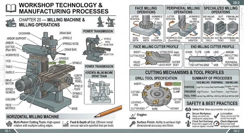
20.1 DEFINITION OF MILLING
Milling is a machining process in which material is removed from a workpiece by a rotating multi-point cutting tool called a milling cutter.
The cutting action is produced by:
Rotation of the milling cutter
Relative movement between cutter and workpiece
Key point
Milling uses a rotating multi-point cutting tool.
This distinguishes milling from conventional turning and shaping, where single-point tools are commonly used.
20.2 PRINCIPLE OF MILLING
In milling:
Rotating cutter + workpiece feed = material removal
The teeth of the cutter enter and leave the workpiece continuously.
Therefore, milling is generally an:
Interrupted cutting process.
20.3 MAIN FEATURES OF MILLING
Important characteristics include:
- Multi-point cutting tool
- Rotary cutting motion
- Intermittent cutting
- High material-removal capability
- Ability to produce complex surfaces
- Suitable for flat, angular and contoured surfaces
20.4 MILLING CUTTER
A milling cutter contains several cutting teeth.
Each tooth acts approximately like a small cutting tool.
Therefore:
Milling is a multi-point machining process.
20.5 MAIN TYPES OF MILLING MACHINES
Important types include:
- Column and knee type milling machine
- Horizontal milling machine
- Vertical milling machine
- Universal milling machine
- Bed-type milling machine
- Planer-type milling machine
- CNC milling machine
20.6 HORIZONTAL MILLING MACHINE
In a horizontal milling machine:
The spindle axis is horizontal.
The cutter is mounted on the spindle, often with an arbor.
Horizontal milling machines are suitable for:
Slab milling
Side milling
Gang milling
Certain gear-cutting operations
20.7 VERTICAL MILLING MACHINE
In a vertical milling machine:
The spindle axis is vertical.
It is commonly used for:
End milling
Face milling
Slot milling
Drilling-related operations in suitable machines
20.8 UNIVERSAL MILLING MACHINE
A universal milling machine is essentially a milling machine in which the table can be swivelled about a horizontal axis, commonly to facilitate:
Helical milling
Angular work
Various indexing operations
The universal milling machine is particularly important for:
Helical milling and gear-related work.
20.9 COLUMN AND KNEE TYPE MILLING MACHINE
Major components include:
Base
Column
Knee
Saddle
Table
Spindle
Arbor/support
Overarm in horizontal machines
20.10 BASE
The base:
Supports the machine
Provides rigidity
May contain coolant arrangements
Transfers machine loads to the foundation
20.11 COLUMN
The column is the main supporting structure.
It houses/supports:
Drive mechanism
Spindle arrangement
Internal gears/mechanisms in many machines
20.12 KNEE
The knee is mounted on the column and supports:
Saddle and table.
It can generally move vertically along the column guideways.
20.13 SADDLE
The saddle is located between:
Knee and table.
It generally provides:
Transverse movement of the table.
20.14 TABLE
The table supports:
The workpiece or work-holding device.
It generally provides longitudinal movement.
T-slots are provided for:
Clamping
Fixtures
Work holding
20.15 SPINDLE
The spindle:
Rotates the milling cutter
Transmits power to the cutter
Determines cutter rotational speed
20.16 ARBOR
An arbor is commonly used in a horizontal milling machine to:
Mount and support milling cutters.
It is supported by the spindle and, depending on design, an arbor support.
20.17 OVERARM
The overarm in a horizontal milling machine provides support for:
The arbor.
This improves rigidity during milling.
20.18 MILLING CUTTERS
Important milling cutters include:
Plain/slab cutter
Face mill
End mill
Side milling cutter
Angle cutter
Form cutter
Slitting saw
T-slot cutter
Dovetail cutter
Gear cutter
Woodruff keyseat cutter
20.19 PLAIN OR SLAB MILLING CUTTER
A plain milling cutter is mainly used for:
Machining large flat surfaces.
It is commonly associated with:
Horizontal milling.
20.20 FACE MILL
A face mill is primarily used to machine:
Flat surfaces.
The cutting edges are located on the face and often the periphery, depending on cutter design.
20.21 END MILL
An end mill can machine:
Slots
Pockets
Keyways
Contours
Vertical and horizontal features
20.22 SIDE MILLING CUTTER
A side milling cutter is mainly used for:
Slots
Grooves
Side surfaces
20.23 SLITTING SAW
A slitting saw is a thin circular milling cutter used for:
Narrow slots
Slitting
Cutting-off applications
20.24 T-SLOT CUTTER
A T-slot cutter is used to produce:
T-shaped slots.
T-slots are commonly required on machine-tool tables for work holding.
20.25 DOVETAIL CUTTER
A dovetail cutter is used to produce:
Dovetail grooves.
20.26 ANGLE CUTTER
An angle milling cutter is used for:
Angular surfaces and grooves.
20.27 GEAR CUTTER
A form gear cutter is used for:
Machining gear teeth in conventional milling operations.
20.28 UP MILLING
Up milling is also called:
Conventional milling.
In up milling:
The cutter rotation at the point of contact is generally opposite to the direction of workpiece feed.
The chip thickness generally:
Starts from zero and increases to maximum.
20.29 DOWN MILLING
Down milling is also called:
Climb milling.
In down milling:
The cutter rotation at the point of contact is generally in the same direction as the workpiece feed.
Chip thickness generally:
Starts at maximum and decreases toward zero.
20.30 UP MILLING — KEY FEATURES
Advantages may include:
Lower tendency for cutter to pull the work under suitable conditions
Commonly used on conventional machines
Cutting action begins with very small chip thickness
Disadvantage:
More rubbing may occur at the beginning of the cut.
20.31 DOWN MILLING — KEY FEATURES
Advantages may include:
Improved surface finish under suitable conditions
Reduced rubbing
Lower tendency for work hardening in some applications
Important limitation:
It can produce a tendency for the cutter to pull the workpiece into the cutter if backlash is present.
Therefore, machine rigidity and backlash control are important.
20.32 COMPARISON: UP VS DOWN MILLING
| Feature | Up Milling | Down Milling |
| Other name | Conventional | Climb |
| Feed vs cutter motion | Opposite | Same |
| Chip thickness | Zero → maximum | Maximum → zero |
| Cutter tendency | Less tendency to pull work | Greater tendency to pull work |
| Backlash sensitivity | Lower | Higher |
| Surface finish | Generally lower | Generally better under suitable conditions |
20.33 MILLING FEED
Feed can be expressed as:
mm/min
mm/tooth
mm/rev
For milling, feed per tooth is especially important.
20.34 FEED RATE
If:
= feed per tooth
= number of teeth
= cutter rpm
Then:
where is feed rate in mm/min.
20.35 CUTTING SPEED
For a milling cutter of diameter rotating at rpm:
where:
= cutting speed in m/min
= cutter diameter in mm
= rpm
20.36 EXAMPLE — CUTTING SPEED
A 100 mm diameter cutter rotates at 300 rpm.
20.37 EXAMPLE — FEED RATE
A cutter has 10 teeth, feed per tooth is 0.1 mm and speed is 500 rpm.
20.38 MILLING OPERATIONS
Important milling operations include:
- Plain milling
- Face milling
- End milling
- Side milling
- Slot milling
- Angular milling
- Form milling
- Gang milling
- Straddle milling
- Gear milling
- Helical milling
- Keyway milling
- Thread milling
20.39 PLAIN MILLING
Plain milling produces:
A flat horizontal surface.
The cutter is generally mounted on a horizontal spindle.
20.40 FACE MILLING
Face milling is used primarily to produce:
Flat surfaces perpendicular to the cutter axis.
20.41 END MILLING
End milling uses an end mill to produce:
Slots
Pockets
Keyways
Contours
20.42 STRADDLE MILLING
In straddle milling:
Two side milling cutters are mounted on the same arbor.
They machine:
Two parallel vertical surfaces simultaneously.
20.43 GANG MILLING
In gang milling:
Two or more cutters are mounted on the same arbor.
Different surfaces can be machined:
In a single pass.
20.44 FORM MILLING
Form milling uses a:
Form cutter
to produce a specially shaped surface.
20.45 HELICAL MILLING
Helical milling is used to produce:
Helical grooves or surfaces.
A universal milling machine and suitable indexing arrangement are commonly used.
20.46 INDEXING
Indexing is the process of:
Rotating the workpiece through a predetermined angle between successive machining operations.
It is particularly important in:
Gear cutting
Splines
Polygonal work
Fluting
20.47 DIVIDING HEAD
A dividing head is used to:
Hold the workpiece
Rotate it accurately
Perform indexing
It is widely used in:
Gear cutting and other equally spaced operations.
20.48 COMMON DIVIDING-HEAD RATIO
A standard dividing head commonly has a worm-and-wheel ratio of:
This means:
40 turns of the crank produce one complete revolution of the work spindle.
20.49 SIMPLE INDEXING
For a 40:1 dividing head:
where is the required number of equal divisions.
Example
For 20 divisions:
Therefore:
2 crank turns per division.
20.50 GEAR CUTTING
Conventional gear cutting can be performed by:
Form milling using a suitable gear cutter.
The dividing head is used to rotate the blank accurately between teeth.
Q1. Milling is a:
A. Single-point machining process
B. Multi-point machining process
C. Casting process
D. Welding process
Answer: B. Multi-point machining process
Explanation: A milling cutter has multiple cutting teeth.
Q2. In milling, the cutting tool:
A. Rotates
B. Always remains stationary
C. Only reciprocates
D. Melts
Answer: A. Rotates
Q3. The cutting tool used in milling is called a:
A. Milling cutter
B. Lathe tool
C. Broach only
D. Drill rod
Answer: A. Milling cutter
Q4. Milling is generally an:
A. Interrupted cutting process
B. Continuous casting process
C. Welding process
D. Forging process
Answer: A. Interrupted cutting process
Q5. In a horizontal milling machine, the spindle axis is:
A. Horizontal
B. Vertical
C. Inclined at 45° always
D. Circular
Answer: A. Horizontal
Q6. In a vertical milling machine, the spindle axis is:
A. Vertical
B. Horizontal
C. Random
D. Parallel to the floor only
Answer: A. Vertical
Q7. A universal milling machine is particularly useful for:
A. Helical milling
B. Welding
C. Casting
D. Forging
Answer: A. Helical milling
Q8. The knee of a column-and-knee milling machine supports the:
A. Saddle and table
B. Motor only
C. Cutter teeth only
D. Foundation only
Answer: A. Saddle and table
Q9. The saddle provides mainly:
A. Transverse movement of the table
B. Rotation of the cutter
C. Workpiece melting
D. Gear tooth cutting directly
Answer: A. Transverse movement of the table
Q10. The table of a milling machine is used to:
A. Support the workpiece
B. Rotate the cutter
C. Drive the motor
D. Support the foundation
Answer: A. Support the workpiece
Q11. The spindle of a milling machine:
A. Rotates the cutter
B. Holds the workpiece only
C. Moves the foundation
D. Produces coolant
Answer: A. Rotates the cutter
Q12. An arbor is mainly used to:
A. Mount milling cutters
B. Hold coolant
C. Measure workpiece temperature
D. Support the foundation
Answer: A. Mount milling cutters
Q13. The overarm in a horizontal milling machine supports the:
A. Arbor
B. Table
C. Workpiece
D. Knee
Answer: A. Arbor
Q14. A plain milling cutter is mainly used for:
A. Flat surface machining
B. Drilling
C. Thread tapping only
D. Grinding
Answer: A. Flat surface machining
Q15. An end mill can be used for:
A. Slots and pockets
B. Only casting
C. Only welding
D. Only forging
Answer: A. Slots and pockets
Q16. A slitting saw is used mainly for:
A. Narrow slots and cutting-off
B. Large cylindrical turning
C. Drilling deep holes
D. Thread tapping only
Answer: A. Narrow slots and cutting-off
Q17. A T-slot cutter is used to produce:
A. T-slots
B. V-belts
C. Circular holes only
D. Threads only
Answer: A. T-slots
Q18. A dovetail cutter is used to produce:
A. Dovetail grooves
B. Cylindrical holes
C. External threads
D. Flat sheets
Answer: A. Dovetail grooves
Q19. Up milling is also known as:
A. Conventional milling
B. Climb milling
C. Down milling
D. Vertical milling
Answer: A. Conventional milling
Q20. Down milling is also known as:
A. Climb milling
B. Conventional milling
C. Slab milling
D. Form milling
Answer: A. Climb milling
Q21. In up milling, chip thickness generally:
A. Starts at zero and increases
B. Starts at maximum and decreases
C. Remains exactly constant
D. Is always zero
Answer: A. Starts at zero and increases
Q22. In down milling, chip thickness generally:
A. Starts at maximum and decreases
B. Starts at zero and increases
C. Remains zero
D. Is independent of feed
Answer: A. Starts at maximum and decreases
Q23. Down milling can be problematic on machines with:
A. Backlash
B. Coolant
C. T-slots
D. Rigid tables
Answer: A. Backlash
Q24. The feed-rate equation for milling is:
A.
B.
C.
D.
Answer: A.
Q25. The standard dividing-head ratio commonly used is:
A. 10:1
B. 20:1
C. 40:1
D. 100:1
Answer: C. 40:1
A. MILLING CUTTERS & OPERATIONS — Q26–45
Q26. Which cutter is most suitable for producing a large flat surface on a horizontal milling machine?
A. Plain milling cutter
B. Slitting saw
C. Dovetail cutter
D. T-slot cutter
Answer: A. Plain milling cutter
Explanation: A plain or slab milling cutter is primarily used for machining broad flat surfaces.
Q27. Face milling is primarily used to produce:
A. Flat surfaces
B. Internal threads
C. Deep holes
D. Cylindrical shafts only
Answer: A. Flat surfaces
Q28. In face milling, the machined surface is generally:
A. Perpendicular to the cutter axis
B. Parallel to the cutter axis only
C. Circular
D. Helical
Answer: A. Perpendicular to the cutter axis
Q29. Which milling operation uses two side milling cutters simultaneously?
A. Straddle milling
B. Face milling
C. Form milling
D. End milling
Answer: A. Straddle milling
Q30. Straddle milling is used to machine:
A. Two parallel vertical surfaces
B. One circular hole
C. One internal thread
D. A spherical surface only
Answer: A. Two parallel vertical surfaces
Q31. Gang milling involves:
A. Several cutters mounted on the same arbor
B. One cutter used repeatedly
C. A drill and reamer
D. A grinding wheel
Answer: A. Several cutters mounted on the same arbor
Q32. The main advantage of gang milling is:
A. Several surfaces can be machined in one pass
B. No cutting tool is required
C. It eliminates feed
D. It eliminates spindle rotation
Answer: A. Several surfaces can be machined in one pass
Q33. Form milling is used to produce:
A. Irregular or specially shaped surfaces
B. Only flat surfaces
C. Only holes
D. Only external threads
Answer: A. Irregular or specially shaped surfaces
Q34. Which cutter is normally used for machining a keyway?
A. End mill or suitable keyway cutter
B. Faceplate
C. Lathe centre
D. Drill chuck only
Answer: A. End mill or suitable keyway cutter
Q35. A Woodruff keyseat cutter is used for:
A. Producing a Woodruff keyseat
B. Cutting external threads
C. Drilling holes
D. Facing shafts
Answer: A. Producing a Woodruff keyseat
Q36. A side milling cutter is mainly used for:
A. Slots and grooves
B. Deep cylindrical holes
C. Welding
D. Casting
Answer: A. Slots and grooves
Q37. A form cutter has:
A. A cutting profile corresponding to the required shape
B. No cutting edges
C. Only one straight cutting edge
D. A grinding surface only
Answer: A. A cutting profile corresponding to the required shape
Q38. A gear milling cutter is used to:
A. Cut gear teeth
B. Drill shafts
C. Grind gears only
D. Produce castings
Answer: A. Cut gear teeth
Q39. Thread milling is used to produce:
A. Threads using a milling cutter
B. Flat surfaces only
C. Holes only
D. Keyways only
Answer: A. Threads using a milling cutter
Q40. Helical milling is used to produce:
A. Helical grooves or surfaces
B. Only flat surfaces
C. Circular holes only
D. T-slots only
Answer: A. Helical grooves or surfaces
Q41. Which operation is most appropriate for producing a T-slot?
A. T-slot milling
B. Face milling only
C. Plain turning
D. Boring
Answer: A. T-slot milling
Q42. Which operation is used to produce a dovetail groove?
A. Dovetail milling
B. Slab milling
C. Face turning
D. Drilling
Answer: A. Dovetail milling
Q43. Milling is especially advantageous for producing:
A. Complex profiles
B. Only simple cylindrical shafts
C. Only holes
D. Only welded joints
Answer: A. Complex profiles
Q44. A milling cutter with teeth on its circumference and sides is generally called a:
A. Side milling cutter
B. Drill
C. Reamer
D. Tap
Answer: A. Side milling cutter
Q45. Which operation is best for machining several different surfaces in one setup?
A. Gang milling
B. Facing
C. Turning
D. Boring
Answer: A. Gang milling
B. CUTTING SPEED & FEED CALCULATIONS — Q46–60
Q46. The cutting-speed formula for milling is:
A.
B.
C.
D.
Answer: A.
Q47. A milling cutter of diameter 100 mm rotates at 300 rpm. Cutting speed is approximately:
A. 47.1 m/min
B. 94.2 m/min
C. 150 m/min
D. 300 m/min
Answer: B. 94.2 m/min
Q48. A 50 mm cutter rotates at 600 rpm. Cutting speed is:
A. 47.1 m/min
B. 94.2 m/min
C. 120 m/min
D. 188.4 m/min
Answer: B. 94.2 m/min
Q49. If cutter diameter remains constant and rpm is doubled, cutting speed:
A. Doubles
B. Halves
C. Remains unchanged
D. Becomes one-fourth
Answer: A. Doubles
Q50. If cutting speed is fixed and cutter diameter is increased, spindle speed should:
A. Decrease
B. Increase
C. Remain constant
D. Become zero
Answer: A. Decrease
Q51. The milling feed-rate formula is:
A.
B.
C.
D.
Answer: A.
Q52. A cutter has 8 teeth, feed per tooth is 0.1 mm and speed is 500 rpm. Feed rate is:
A. 200 mm/min
B. 300 mm/min
C. 400 mm/min
D. 500 mm/min
Answer: C. 400 mm/min
Q53. A 10-tooth cutter has feed per tooth of 0.15 mm and rotates at 400 rpm. Feed rate is:
A. 400 mm/min
B. 500 mm/min
C. 600 mm/min
D. 750 mm/min
Answer: C. 600 mm/min
Q54. If feed per tooth is doubled while other parameters remain constant, feed rate:
A. Doubles
B. Halves
C. Remains unchanged
D. Becomes zero
Answer: A. Doubles
Q55. A cutter has 12 teeth and feed rate is 720 mm/min at 600 rpm. Feed per tooth is:
A. 0.05 mm
B. 0.10 mm
C. 0.15 mm
D. 0.20 mm
Answer: B. 0.10 mm
Q56. A milling cutter rotates at 400 rpm and has 10 teeth. If feed per tooth is 0.2 mm, feed rate is:
A. 400 mm/min
B. 600 mm/min
C. 800 mm/min
D. 1000 mm/min
Answer: C. 800 mm/min
Q57. If a 200 mm long surface is machined at a feed rate of 100 mm/min, theoretical machining time is:
A. 1 min
B. 2 min
C. 3 min
D. 4 min
Answer: B. 2 min
Q58. If milling length is 300 mm and feed rate is 150 mm/min, machining time is:
A. 1 min
B. 2 min
C. 3 min
D. 4 min
Answer: B. 2 min
Q59. Actual machining time may be greater than the simple value because of:
A. Approach and over-travel
B. Absence of cutting
C. Zero feed
D. Zero cutter rotation
Answer: A. Approach and over-travel
Q60. Increasing feed rate generally increases:
A. Material removal rate
B. Cutter diameter
C. Workpiece hardness
D. Spindle diameter
Answer: A. Material removal rate
C. UP MILLING & DOWN MILLING — Q61–70
Q61. In up milling, the cutter rotates:
A. Opposite to work feed at the cutting point
B. In the same direction as feed
C. Without rotation
D. Vertically only
Answer: A. Opposite to work feed at the cutting point
Q62. In down milling, cutter rotation at the cutting point is:
A. In the same direction as feed
B. Opposite to feed
C. Perpendicular to feed always
D. Zero
Answer: A. In the same direction as feed
Q63. In up milling, chip thickness:
A. Increases from zero to maximum
B. Decreases from maximum to zero
C. Remains constant
D. Is always zero
Answer: A. Increases from zero to maximum
Q64. In down milling, chip thickness:
A. Starts maximum and decreases to zero
B. Starts zero and increases
C. Remains constant
D. Is always zero
Answer: A. Starts maximum and decreases to zero
Q65. Down milling is also called:
A. Climb milling
B. Conventional milling
C. Slab milling
D. Form milling
Answer: A. Climb milling
Q66. Up milling is also called:
A. Conventional milling
B. Climb milling
C. Face milling
D. Gang milling
Answer: A. Conventional milling
Q67. Which operation is more sensitive to backlash?
A. Down milling
B. Up milling
C. Both are always identical
D. Neither
Answer: A. Down milling
Q68. A major advantage of down milling under suitable machine conditions is:
A. Better surface finish
B. Zero cutting force
C. No cutter rotation
D. No work holding
Answer: A. Better surface finish
Q69. In up milling, tooth thickness at the start of cutting is:
A. Very small/approximately zero
B. Maximum
C. Infinite
D. Constant
Answer: A. Very small/approximately zero
Q70. In down milling, the cutter tends to:
A. Pull the workpiece in the feed direction
B. Push the workpiece completely backward
C. Stop rotating
D. Eliminate all cutting forces
Answer: A. Pull the workpiece in the feed direction
D. INDEXING & DIVIDING HEAD — Q71–85
Q71. Indexing is used to:
A. Rotate the workpiece through predetermined angles
B. Increase workpiece hardness
C. Sharpen the cutter automatically
D. Reduce cutter diameter
Answer: A. Rotate the workpiece through predetermined angles
Q72. A dividing head is primarily used for:
A. Accurate angular positioning of work
B. Grinding only
C. Welding
D. Casting
Answer: A. Accurate angular positioning of work
Q73. A standard dividing head commonly has a ratio of:
A. 10:1
B. 20:1
C. 40:1
D. 100:1
Answer: C. 40:1
Q74. For a 40:1 dividing head, one complete revolution of the work spindle requires:
A. 10 crank turns
B. 20 crank turns
C. 40 crank turns
D. 80 crank turns
Answer: C. 40 crank turns
Q75. For a 40:1 dividing head, crank movement for 10 divisions is:
A. 2 turns
B. 4 turns
C. 6 turns
D. 10 turns
Answer: B. 4 turns
Q76. For 20 equal divisions, crank movement is:
A. 1 turn
B. 2 turns
C. 4 turns
D. 20 turns
Answer: B. 2 turns
Q77. For 40 equal divisions, crank movement per division is:
A. 0.5 turn
B. 1 turn
C. 2 turns
D. 4 turns
Answer: B. 1 turn
Q78. For 8 equal divisions, crank movement is:
A. 2 turns
B. 4 turns
C. 5 turns
D. 8 turns
Answer: C. 5 turns
Q79. For 16 divisions, crank movement is:
A. 1 turn
B. 2 turns
C. 2.5 turns
D. 4 turns
Answer: C. 2.5 turns
Q80. If 5 crank turns rotate the workpiece through one-eighth revolution, the dividing-head ratio is:
A. 20:1
B. 30:1
C. 40:1
D. 50:1
Answer: C. 40:1
Q81. The dividing head is particularly important in:
A. Gear cutting
B. Welding
C. Forging
D. Casting
Answer: A. Gear cutting
Q82. Indexing is required when machining:
A. Equally spaced teeth
B. A single flat surface only
C. A simple hole only
D. A random surface
Answer: A. Equally spaced teeth
Q83. A dividing head can be used to produce:
A. Polygonal shapes
B. Only circular holes
C. Only flat surfaces
D. Only threads
Answer: A. Polygonal shapes
Q84. The worm and worm wheel in a dividing head provide:
A. Large reduction and accurate rotation
B. High-speed direct rotation only
C. Grinding action
D. Welding pressure
Answer: A. Large reduction and accurate rotation
Q85. Simple indexing formula for a 40:1 dividing head is:
A.
B.
C.
D.
Answer: A.
E. GEAR CUTTING & HELICAL MILLING — Q86–94
Q86. Conventional gear milling requires:
A. Gear cutter and indexing arrangement
B. Grinding wheel only
C. Drill only
D. Lathe centre only
Answer: A. Gear cutter and indexing arrangement
Q87. The dividing head is used during gear cutting to:
A. Index the gear blank
B. Rotate the cutter only
C. Sharpen the cutter
D. Increase cutting speed
Answer: A. Index the gear blank
Q88. The number of spaces between successive gear teeth is controlled by:
A. Indexing
B. Coolant
C. Cutting fluid pressure
D. Machine foundation
Answer: A. Indexing
Q89. Helical milling is used to produce:
A. Helical grooves
B. Only flat surfaces
C. Only circular holes
D. Only T-slots
Answer: A. Helical grooves
Q90. A universal milling machine is particularly suitable for:
A. Helical milling
B. Welding
C. Forging
D. Casting
Answer: A. Helical milling
Q91. A helix is a curve generated by:
A. Combined rotational and axial movement
B. Only vertical movement
C. Only horizontal movement
D. Only random movement
Answer: A. Combined rotational and axial movement
Q92. A helical gear tooth is:
A. Inclined relative to the gear axis
B. Always exactly parallel to the axis
C. Always perpendicular to the axis
D. Circular only
Answer: A. Inclined relative to the gear axis
Q93. In gear milling, a suitable cutter is selected according to:
A. Gear tooth form and module/DP system
B. Workpiece colour
C. Machine paint
D. Coolant colour
Answer: A. Gear tooth form and module/DP system
Q94. Indexing accuracy is important in gear cutting because:
A. Teeth must be equally spaced
B. Gear must be melted
C. Cutter must remain stationary
D. No rotation is required
Answer: A. Teeth must be equally spaced
F. ADVANCED EXAM-ORIENTED QUESTIONS — Q95–100
Q95. A 120 mm diameter cutter rotates at 250 rpm. Cutting speed is approximately:
A. 47.1 m/min
B. 78.5 m/min
C. 94.2 m/min
D. 120 m/min
Answer: B. 94.2 m/min
Calculation:
Correction: Since , therefore:
So the correct answer is C. 94.2 m/min.
Q96. A milling cutter has 12 teeth and rotates at 500 rpm. If feed per tooth is 0.08 mm, feed rate is:
A. 240 mm/min
B. 400 mm/min
C. 480 mm/min
D. 600 mm/min
Answer: C. 480 mm/min
Q97. A 40:1 dividing head is required to make 25 equal divisions. Crank movement per division is:
A. 1.2 turns
B. 1.6 turns
C. 2 turns
D. 2.5 turns
Answer: B. 1.6 turns
Q98. Which combination is correct?
A. Plain milling—flat surface; Straddle milling—two parallel surfaces; Gang milling—multiple cutters
B. Plain milling—threading; Straddle milling—drilling; Gang milling—turning
C. Plain milling—welding; Straddle milling—casting; Gang milling—forging
D. Plain milling—grinding; Straddle milling—broaching; Gang milling—drilling
Answer: A.
Q99. A milling cutter has 10 teeth, rotates at 600 rpm and feed per tooth is 0.2 mm. The feed rate is:
A. 600 mm/min
B. 800 mm/min
C. 1000 mm/min
D. 1200 mm/min
Answer: D. 1200 mm/min
Q100. Which statement is correct?
A. Milling uses a rotating multi-point cutter
B. Milling always uses a single-point stationary tool
C. Milling cannot produce slots
D. Milling cannot produce flat surfaces
Answer: A. Milling uses a rotating multi-point cutter
CHAPTER 20 — QUICK REVISION TABLE
| Topic | Key Point |
| Milling | Multi-point machining process |
| Cutter | Rotating multi-tooth tool |
| Horizontal milling | Horizontal spindle |
| Vertical milling | Vertical spindle |
| Universal milling | Suitable for helical work |
| Plain milling | Flat surfaces |
| Face milling | Flat faces |
| End milling | Slots, pockets, keyways |
| Side milling | Slots and grooves |
| Straddle milling | Two parallel surfaces |
| Gang milling | Several cutters |
| Form milling | Irregular profiles |
| Slitting saw | Narrow slots/cutting-off |
| T-slot cutter | T-slots |
| Dovetail cutter | Dovetail grooves |
| Up milling | Conventional milling |
| Down milling | Climb milling |
| Up milling chip | Zero → maximum |
| Down milling chip | Maximum → zero |
| Feed rate | |
| Cutting speed | |
| Indexing | Angular positioning |
| Dividing head | Accurate work rotation |
| Standard ratio | 40:1 |
| Simple indexing | |
| Gear milling | Gear cutter + indexing |
| Helical milling | Helical grooves/surfaces |
CHAPTER 21 — FULL-LENGTH MOCK TESTS
MOCK TEST 1 — QUESTIONS 1–100
Mechanical & Manufacturing Engineering — Complete Exam Practice
Instructions: Each question has four options. Select the most appropriate answer. The correct answer and a concise explanation are provided after each question.
SECTION A — ENGINEERING MATERIALS & MECHANICAL PROPERTIES
Q1. Which of the following is a mechanical property of a material?
A. Thermal conductivity
B. Hardness
C. Electrical resistivity
D. Density
Answer: B. Hardness
Explanation: Hardness is the resistance of a material to indentation, scratching, penetration, or wear.
Q2. Which test is commonly used to determine the hardness of a material using a spherical indenter?
A. Brinell test
B. Charpy test
C. Izod test
D. Fatigue test
Answer: A. Brinell test
Explanation: The Brinell hardness test uses a hardened steel or tungsten-carbide ball as the indenter.
Q3. According to Hooke’s law, within the elastic limit:
A. Stress is proportional to strain
B. Stress is inversely proportional to strain
C. Stress is proportional to the square of strain
D. Stress is independent of strain
Answer: A. Stress is proportional to strain
Explanation: Within the elastic limit, stress is directly proportional to strain:
where is Young’s modulus.
Q4. What is the SI unit of Young’s modulus?
A. N
B. N/m
C. Pa
D. m/N
Answer: C. Pa
Explanation: Young’s modulus is stress divided by strain. Since strain is dimensionless, its unit is Pascal (Pa).
Q5. A bar has an original length of 2 m and elongates by 1 mm. What is the strain?
A. 0.0005
B. 0.005
C. 0.05
D. 0.5
Answer: A. 0.0005
Explanation:
Q6. Cast iron is generally classified as:
A. Highly ductile
B. Brittle
C. Elastomeric
D. Fibrous
Answer: B. Brittle
Explanation: Cast iron generally has high compressive strength but relatively low tensile ductility, making it a brittle material.
Q7. Mild steel is generally characterized by:
A. Low carbon content
B. Extremely high carbon content
C. Zero carbon content
D. More than 5% carbon content
Answer: A. Low carbon content
Explanation: Mild steel is a low-carbon steel known for good ductility, machinability, and weldability.
Q8. The corrosion resistance of stainless steel is mainly due to the presence of:
A. Chromium
B. Lead
C. Sulphur
D. Phosphorus
Answer: A. Chromium
Explanation: Chromium forms a thin, protective passive oxide layer on the surface of stainless steel.
Q9. Brass is primarily an alloy of:
A. Copper and zinc
B. Copper and tin
C. Iron and carbon
D. Aluminium and silicon
Answer: A. Copper and zinc
Explanation: Brass is mainly composed of copper and zinc.
Q10. Bronze is traditionally an alloy of:
A. Copper and tin
B. Copper and zinc
C. Iron and nickel
D. Aluminium and zinc
Answer: A. Copper and tin
Explanation: Traditional bronze consists primarily of copper and tin.
SECTION B — MACHINE TOOLS & MACHINING
Q11. What is the principal function of a lathe?
A. Machining a rotating workpiece
B. Performing only drilling operations
C. Performing only grinding operations
D. Performing only welding operations
Answer: A. Machining a rotating workpiece
Explanation: In a conventional lathe, the workpiece rotates while the cutting tool performs the required machining operation.
Q12. The primary purpose of a facing operation on a lathe is to produce:
A. A flat end surface
B. An internal thread
C. A gear tooth
D. A tapered hole only
Answer: A. A flat end surface
Explanation: Facing removes material from the end of a workpiece to produce a flat surface perpendicular to its axis.
Q13. During conventional turning on a lathe, the main cutting motion is provided by:
A. The workpiece
B. The tool post
C. The tailstock
D. The coolant system
Answer: A. The workpiece
Explanation: The workpiece rotates with the spindle, providing the primary cutting motion.
Q14. Taper turning on a lathe produces:
A. A conical surface
B. A completely flat surface
C. A gear profile
D. A spherical cavity
Answer: A. A conical surface
Explanation: Taper turning produces a surface whose diameter changes progressively along the length.
Q15. In milling, the cutting tool:
A. Rotates
B. Remains permanently stationary
C. Only moves vertically
D. Only moves manually
Answer: A. Rotates
Explanation: Milling uses a rotating multi-point cutting tool to remove material from the workpiece.
Q16. The primary purpose of drilling is to:
A. Produce a hole
B. Produce a flat surface
C. Produce an external thread
D. Harden the surface
Answer: A. Produce a hole
Explanation: A drill is a rotary cutting tool primarily used to produce cylindrical holes.
Q17. Reaming is primarily used to:
A. Accurately finish an existing hole
B. Produce a casting
C. Join two components
D. Forge a component
Answer: A. Accurately finish an existing hole
Explanation: Reaming improves the dimensional accuracy and surface finish of a previously drilled or bored hole.
Q18. Tapping is used to produce:
A. Internal threads
B. External threads
C. Flat surfaces
D. Keyways only
Answer: A. Internal threads
Explanation: A tap is a cutting tool used to produce internal screw threads.
Q19. A broach generally consists of:
A. Multiple cutting teeth arranged progressively
B. A single blunt cutting edge
C. Only abrasive grains
D. A smooth cylindrical surface without teeth
Answer: A. Multiple cutting teeth arranged progressively
Explanation: A broach contains a series of cutting teeth that progressively remove material as the tool moves through the workpiece.
Q20. The cutting action in grinding is mainly performed by:
A. Abrasive grains
B. Rubber particles
C. Wooden teeth
D. Plastic inserts
Answer: A. Abrasive grains
Explanation: Grinding wheels contain abrasive grains that act as numerous small cutting edges.
SECTION C — CASTING & FOUNDRY
Q21. In casting, molten metal is:
A. Poured into a mould cavity
B. Rolled between rollers
C. Forced through a cutting tool
D. Welded to another component
Answer: A. Poured into a mould cavity
Explanation: The molten metal fills the mould cavity and solidifies to form the required casting.
Q22. The main purpose of a pattern in casting is to:
A. Produce the mould cavity
B. Melt the metal
C. Supply welding current
D. Grind the casting
Answer: A. Produce the mould cavity
Explanation: A pattern represents the desired shape of the casting and is used to create the mould cavity.
Q23. In sand casting, the mould is primarily made from:
A. Sand
B. Pure steel
C. Rubber
D. Glass
Answer: A. Sand
Explanation: Sand moulding is one of the most widely used casting processes because of its versatility and relatively low cost.
Q24. The primary function of a riser is to:
A. Compensate for solidification shrinkage
B. Guide a cutting tool
C. Supply welding current
D. Remove machining chips
Answer: A. Compensate for solidification shrinkage
Explanation: A riser acts as a reservoir of molten metal that feeds the casting as it contracts during solidification.
Q25. The main function of a sprue is to:
A. Carry molten metal into the gating system
B. Harden the casting
C. Grind the casting surface
D. Hold the pattern permanently
Answer: A. Carry molten metal into the gating system
Explanation: The sprue is a vertical passage through which molten metal flows from the pouring basin into the runners and gates.
Q26. A core is primarily used in casting to:
A. Produce internal cavities
B. Improve external surface colour
C. Cut the casting
D. Increase cutting speed
Answer: A. Produce internal cavities
Explanation: Cores are placed inside moulds to create holes, passages, and other internal cavities.
Q27. Blowholes in castings are primarily associated with:
A. Gas-related defects
B. Excessive tool wear
C. Incorrect thread geometry
D. Grinding wheel imbalance
Answer: A. Gas-related defects
Explanation: Blowholes can occur when gases become trapped within the molten metal during solidification.
Q28. Casting porosity refers to:
A. Voids or cavities within the casting
B. Excessive hardness
C. Perfect surface finish
D. Increased dimensional accuracy
Answer: A. Voids or cavities within the casting
Explanation: Porosity consists of unwanted voids that may arise from gas entrapment or solidification-related effects.
SECTION D — WELDING & JOINING
Q29. In arc welding, the primary source of heat is:
A. An electric arc
B. A water jet
C. Compressed air only
D. Mechanical friction only
Answer: A. An electric arc
Explanation: The electric arc produces intense heat sufficient to melt the base metal and, where applicable, the filler metal.
Q30. The primary purpose of welding is to:
A. Permanently join components
B. Measure dimensions
C. Polish surfaces
D. Produce holes
Answer: A. Permanently join components
Explanation: Welding produces a permanent joint by fusion or another welding mechanism.
Q31. Which fuel gas is commonly used in oxy-fuel welding?
A. Acetylene
B. Nitrogen
C. Carbon dioxide
D. Helium
Answer: A. Acetylene
Explanation: Oxy-acetylene welding uses oxygen and acetylene to produce a high-temperature flame.
Q32. A consumable welding electrode can:
A. Carry current and provide filler metal
B. Only measure temperature
C. Only cool the workpiece
D. Only support the welding machine
Answer: A. Carry current and provide filler metal
Explanation: In consumable electrode processes, the electrode conducts current and melts to contribute filler metal to the weld.
Q33. Weld porosity is primarily caused by:
A. Gas entrapment
B. Excessive dimensional accuracy
C. Incorrect gear ratio
D. Low spindle speed
Answer: A. Gas entrapment
Explanation: Gas trapped in the molten weld pool can produce pores after solidification.
Q34. Excessive heat input during welding can cause:
A. Distortion
B. Zero thermal expansion
C. Perfect dimensional accuracy
D. Elimination of residual stress
Answer: A. Distortion
Explanation: Uneven heating and cooling can create thermal stresses and distortion in welded components.
Q35. PPE in welding stands for:
A. Personal Protective Equipment
B. Production Process Engineering
C. Power Protection Element
D. Primary Processing Equipment
Answer: A. Personal Protective Equipment
Explanation: Welding PPE includes suitable helmets, gloves, protective clothing, safety footwear, and other protective equipment.
SECTION E — METAL FORMING
Q36. Forging primarily shapes metal using:
A. Compressive forces
B. Tensile forces only
C. Chemical dissolution
D. Electrical discharge
Answer: A. Compressive forces
Explanation: Forging plastically deforms metal under compressive forces.
Q37. In rolling, the workpiece passes:
A. Between rotating rolls
B. Through a welding electrode
C. Through a grinding wheel only
D. Through a casting core
Answer: A. Between rotating rolls
Explanation: Rolling reduces thickness or changes the cross-section by passing material between rotating rolls.
Q38. In extrusion, material is:
A. Forced through a die opening
B. Melted without a die
C. Welded to another component
D. Removed using abrasive grains only
Answer: A. Forced through a die opening
Explanation: Extrusion forces a billet through a die to produce a continuous product with the desired cross-section.
Q39. In blanking, the punched-out portion is generally:
A. The required blank or product
B. Always waste material
C. The punch
D. The die
Answer: A. The required blank or product
Explanation: In blanking, the cut-out portion is the desired product, while the remaining sheet is scrap.
Q40. The primary purpose of bending a sheet-metal component is to:
A. Change its shape
B. Change only its colour
C. Increase its melting point
D. Convert it into a casting
Answer: A. Change its shape
Explanation: Bending produces a permanent angular or curved shape without intentionally removing material.
SECTION F — HEAT TREATMENT
Q41. A common purpose of annealing is to:
A. Soften the material and improve ductility
B. Always maximize hardness
C. Melt the material
D. Increase porosity
Answer: A. Soften the material and improve ductility
Explanation: Annealing can reduce hardness, relieve internal stresses, and improve machinability and ductility.
Q42. Quenching involves:
A. Rapid cooling of heated material
B. Very slow cooling in a furnace only
C. Melting the material
D. Cold working only
Answer: A. Rapid cooling of heated material
Explanation: Quenching rapidly cools a suitably heated material to obtain desired microstructural and mechanical changes.
Q43. Tempering is mainly performed to:
A. Reduce the brittleness of quenched steel
B. Melt the steel
C. Increase porosity
D. Remove all carbon
Answer: A. Reduce the brittleness of quenched steel
Explanation: Tempering improves toughness and reduces excessive brittleness after hardening.
Q44. Normalizing generally involves heating steel above the critical temperature followed by:
A. Air cooling
B. Water quenching only
C. Oil quenching only
D. Furnace melting
Answer: A. Air cooling
Explanation: Normalizing refines the grain structure and produces a relatively uniform microstructure through air cooling.
Q45. The principal objective of case hardening is to obtain:
A. A hard surface with a relatively tough core
B. A completely brittle component
C. A completely soft surface
D. A molten core
Answer: A. A hard surface with a relatively tough core
Explanation: Case hardening improves surface wear resistance while retaining useful toughness in the core.
SECTION G — METROLOGY & INSPECTION
Q46. A vernier caliper can commonly measure:
A. External, internal, and depth dimensions
B. Temperature only
C. Weight only
D. Pressure only
Answer: A. External, internal, and depth dimensions
Explanation: A vernier caliper is a versatile dimensional measuring instrument.
Q47. A micrometer is primarily used for:
A. Precise dimensional measurement
B. Measuring temperature
C. Measuring pressure
D. Measuring electrical resistance
Answer: A. Precise dimensional measurement
Explanation: The micrometer screw mechanism allows accurate measurement of small dimensions.
Q48. A dial indicator is commonly used to detect:
A. Small dimensional deviations and runout
B. Material composition
C. Melting temperature
D. Chemical concentration
Answer: A. Small dimensional deviations and runout
Explanation: Dial indicators are widely used for checking alignment, runout, flatness, and small displacement.
Q49. Tolerance is defined as:
A. The permissible variation in a dimension
B. The exact nominal dimension
C. The material density
D. The surface colour
Answer: A. The permissible variation in a dimension
Explanation: Tolerance specifies the allowable dimensional variation from the specified size.
Q50. In a clearance fit:
A. The hole is always larger than the shaft
B. The shaft is always larger than the hole
C. Hole and shaft are always identical
D. No tolerance is allowed
Answer: A. The hole is always larger than the shaft
Explanation: A clearance fit always provides positive clearance between the mating components.
SECTION H — PRODUCTION & INDUSTRIAL ENGINEERING
Q51. Productivity is generally expressed as:
A. Output / Input
B. Input / Output
C. Output × Input
D. Output + Input
Answer: A. Output / Input
Explanation: Productivity measures how efficiently inputs are converted into outputs.
Q52. Work study mainly consists of:
A. Method study and work measurement
B. Casting and welding
C. Forging and rolling
D. Drilling and grinding
Answer: A. Method study and work measurement
Explanation: Work study aims to improve work methods and determine the time required to perform a task.
Q53. The main purpose of time study is to determine:
A. Standard time
B. Melting temperature
C. Tool material
D. Casting pattern size
Answer: A. Standard time
Explanation: Time study establishes the time required by a qualified worker to perform a task under specified conditions.
Q54. Inventory refers to:
A. Stored materials, components, work-in-process, and finished goods
B. Only machines
C. Only workers
D. Only finished products
Answer: A. Stored materials, components, work-in-process, and finished goods
Explanation: Inventory can exist at several stages of the production system.
Q55. The primary objective of EOQ is to:
A. Balance relevant ordering and holding costs
B. Maximize inventory indefinitely
C. Eliminate production
D. Increase labour requirements
Answer: A. Balance relevant ordering and holding costs
Explanation: Economic Order Quantity identifies an order size that minimizes the relevant total inventory costs under the model assumptions.
Q56. Quality control primarily aims to:
A. Ensure products meet specified requirements
B. Increase defects
C. Increase material waste
D. Eliminate inspection
Answer: A. Ensure products meet specified requirements
Explanation: Quality control uses inspection, measurement, and process controls to maintain required quality.
Q57. Six Sigma primarily focuses on:
A. Reducing process variation and defects
B. Increasing machine weight
C. Increasing inventory
D. Increasing material waste
Answer: A. Reducing process variation and defects
Explanation: Six Sigma is a data-driven methodology for improving process performance and reducing defects.
Q58. Preventive maintenance is performed:
A. Before equipment failure occurs
B. Only after complete equipment failure
C. Before purchasing equipment
D. Only when production stops unexpectedly
Answer: A. Before equipment failure occurs
Explanation: Preventive maintenance is planned and performed at predetermined intervals or conditions to reduce the likelihood of failure.
Q59. Breakdown maintenance is generally performed:
A. After equipment failure
B. Before equipment installation
C. Before every production cycle
D. Only during equipment design
Answer: A. After equipment failure
Explanation: Breakdown maintenance restores equipment after an actual failure has occurred.
Q60. In the 5S methodology, the first S represents:
A. Sort
B. Standardize
C. Sustain
D. Safety
Answer: A. Sort
Explanation: Sort involves identifying and removing unnecessary items from the workplace.
SECTION I — CNC, CAD, CAM & AUTOMATION
Q61. CNC stands for:
A. Computer Numerical Control
B. Central Numerical Control
C. Computer Network Control
D. Controlled Numerical Computer
Answer: A. Computer Numerical Control
Explanation: CNC machines operate according to programmed numerical instructions.
Q62. In standard CNC programming, G01 generally represents:
A. Linear interpolation
B. Rapid positioning
C. Program stop
D. Spindle stop
Answer: A. Linear interpolation
Explanation: G01 commands controlled straight-line movement at the programmed feed rate.
Q63. In standard CNC programming, G02 generally represents:
A. Clockwise circular interpolation
B. Counterclockwise circular interpolation
C. Rapid positioning
D. Tool change
Answer: A. Clockwise circular interpolation
Explanation: G02 is commonly used to command clockwise circular interpolation in the active machining plane.
Q64. In standard CNC programming, M03 generally commands:
A. Clockwise spindle rotation
B. Spindle stop
C. Coolant stop
D. Program end
Answer: A. Clockwise spindle rotation
Explanation: M03 commonly starts spindle rotation in the clockwise direction.
Q65. A work offset in CNC machining is used to:
A. Establish the workpiece coordinate system
B. Sharpen the cutting tool
C. Increase coolant pressure
D. Change the machine structure
Answer: A. Establish the workpiece coordinate system
Explanation: Work offsets relate programmed workpiece coordinates to the machine’s coordinate system.
Q66. ATC in a CNC machine stands for:
A. Automatic Tool Changer
B. Automatic Turning Control
C. Advanced Tool Computer
D. Automatic Transfer Circuit
Answer: A. Automatic Tool Changer
Explanation: An ATC automatically changes cutting tools according to the machining program.
Q67. CAD stands for:
A. Computer-Aided Design
B. Computer-Aided Drilling
C. Controlled Automatic Design
D. Computer Analysis Device
Answer: A. Computer-Aided Design
Explanation: CAD software is used to create, modify, analyze, and document engineering designs.
Q68. CAM stands for:
A. Computer-Aided Manufacturing
B. Computer-Aided Measurement
C. Central Automated Machine
D. Computer Analysis Method
Answer: A. Computer-Aided Manufacturing
Explanation: CAM uses computer systems to support manufacturing activities such as tool-path generation.
Q69. PLC stands for:
A. Programmable Logic Controller
B. Production Line Computer
C. Programmable Lathe Controller
D. Process Load Calculator
Answer: A. Programmable Logic Controller
Explanation: PLCs are widely used to control automated industrial processes and machinery.
Q70. The primary function of a robot end effector is to:
A. Perform the required task using a suitable tool or gripper
B. Store the robot program
C. Supply electrical power
D. Cool the robot
Answer: A. Perform the required task using a suitable tool or gripper
Explanation: The end effector interacts directly with the workpiece or environment.
SECTION J — ADVANCED MANUFACTURING & SAFETY
Q71. In Electrical Discharge Machining, the workpiece must generally be:
A. Electrically conductive
B. Electrically insulating
C. Made only of wood
D. Made only of rubber
Answer: A. Electrically conductive
Explanation: EDM removes material through controlled electrical discharges between the tool electrode and conductive workpiece.
Q72. Ultrasonic Machining is particularly suitable for:
A. Hard and brittle materials
B. Soft rubber only
C. Wood only
D. Liquid materials
Answer: A. Hard and brittle materials
Explanation: USM uses high-frequency tool vibration and abrasive slurry and is especially useful for hard, brittle, and non-conductive materials.
Q73. In Electrochemical Machining, the workpiece generally acts as the:
A. Anode
B. Cathode
C. Insulator
D. Dielectric
Answer: A. Anode
Explanation: Material is removed from the anodic workpiece by electrochemical dissolution.
Q74. Laser Beam Machining removes material primarily through:
A. Localized melting and vaporization
B. Conventional forging
C. Electrochemical dissolution
D. Mechanical rolling
Answer: A. Localized melting and vaporization
Explanation: A highly focused laser beam produces intense localized heating, causing melting and/or vaporization.
Q75. Abrasive Water Jet Machining uses:
A. High-pressure water with abrasive particles
B. Water only at atmospheric pressure
C. Electrical current through water only
D. Molten metal
Answer: A. High-pressure water with abrasive particles
Explanation: Abrasive particles significantly increase the cutting capability of the high-velocity water jet.
Q76. The principal difference between a jig and a fixture is that:
A. A jig guides the cutting tool, while a fixture primarily holds and locates the workpiece
B. A fixture guides the cutting tool, while a jig only holds the workpiece
C. Both are measuring instruments
D. Both are cutting tools
Answer: A. A jig guides the cutting tool, while a fixture primarily holds and locates the workpiece
Explanation: Tool guidance is the distinguishing feature of a jig.
Q77. The 3-2-1 principle is associated with:
A. Workpiece location
B. Welding current control
C. Heat treatment
D. Grinding wheel selection
Answer: A. Workpiece location
Explanation: The 3-2-1 principle provides a systematic method for restricting the six degrees of freedom of a workpiece.
Q78. Safety goggles are primarily used to protect:
A. The eyes
B. The feet
C. The hands
D. The ears
Answer: A. The eyes
Explanation: Safety goggles protect the eyes against flying particles, chips, sparks, and other hazards.
Q79. A machine guard is primarily intended to:
A. Protect operators from hazardous moving parts
B. Increase cutting speed
C. Increase material hardness
D. Improve surface finish directly
Answer: A. Protect operators from hazardous moving parts
Explanation: Machine guards help prevent accidental contact with moving or dangerous machine components.
Q80. Lockout/Tagout procedures are intended to:
A. Prevent unexpected energization or startup during servicing
B. Increase machine speed
C. Increase production rate
D. Reduce tool diameter
Answer: A. Prevent unexpected energization or startup during servicing
Explanation: Lockout/Tagout isolates hazardous energy sources before maintenance or servicing.
SECTION K — NUMERICAL & APPLICATION-BASED QUESTIONS
Q81. A shaft diameter is reduced from 50 mm to 45 mm during turning. What is the radial depth of cut?
A. 2.0 mm
B. 2.5 mm
C. 5.0 mm
D. 7.5 mm
Answer: B. 2.5 mm
Explanation:
Q82. A lathe has a workpiece diameter of 100 mm and spindle speed of 300 rpm. What is the cutting speed?
A. 31.4 m/min
B. 47.1 m/min
C. 94.2 m/min
D. 300 m/min
Answer: C. 94.2 m/min
Explanation:
Q83. A turning operation uses a feed of 0.2 mm/rev at a spindle speed of 500 rpm. What is the feed rate?
A. 50 mm/min
B. 75 mm/min
C. 100 mm/min
D. 250 mm/min
Answer: C. 100 mm/min
Explanation:
Q84. A rectangular plate is 200 mm long and 100 mm wide. What is its surface area?
A. 2,000 mm²
B. 10,000 mm²
C. 20,000 mm²
D. 30,000 mm²
Answer: C. 20,000 mm²
Explanation:
Q85. A force of 10,000 N acts over an area of 500 mm². What is the resulting stress?
A. 10 N/mm²
B. 20 N/mm²
C. 50 N/mm²
D. 200 N/mm²
Answer: B. 20 N/mm²
Q86. A component has a basic size of 50 mm with a tolerance of ±0.05 mm. What is the maximum permissible size?
A. 49.95 mm
B. 50.00 mm
C. 50.05 mm
D. 50.50 mm
Answer: C. 50.05 mm
Q87. For the component in Question 86, what is the minimum permissible size?
A. 49.95 mm
B. 50.00 mm
C. 50.05 mm
D. 49.50 mm
Answer: A. 49.95 mm
Q88. A hole has a diameter of 40.06 mm and the mating shaft has a diameter of 40.00 mm. What is the clearance?
A. 0.006 mm
B. 0.06 mm
C. 0.6 mm
D. 6 mm
Answer: B. 0.06 mm
Q89. A machine produces 400 components in 8 hours. What is its average production rate?
A. 25 components/hour
B. 40 components/hour
C. 50 components/hour
D. 80 components/hour
Answer: C. 50 components/hour
Q90. A machine has a cycle time of 2 minutes per component. What is its theoretical production rate?
A. 20 components/hour
B. 30 components/hour
C. 60 components/hour
D. 120 components/hour
Answer: B. 30 components/hour
SECTION L — MIXED ENGINEERING QUESTIONS
Q91. Which of the following is a thermoplastic?
A. PVC
B. Bakelite
C. Epoxy thermoset
D. Melamine formaldehyde
Answer: A. PVC
Explanation: Polyvinyl chloride (PVC) is a widely used thermoplastic polymer.
Q92. Which statement correctly describes a thermosetting plastic?
A. It cannot normally be remelted and reshaped after curing
B. It can always be repeatedly melted and reshaped
C. It is always a metal
D. It is always a liquid
Answer: A. It cannot normally be remelted and reshaped after curing
Explanation: Thermosetting polymers form a cross-linked structure during curing and cannot normally be remelted like thermoplastics.
Q93. A composite material generally contains:
A. Two or more distinct constituent materials
B. Only pure iron
C. Only one element
D. Only a liquid phase
Answer: A. Two or more distinct constituent materials
Explanation: Composites combine different materials, typically a matrix and reinforcement, to obtain improved or tailored properties.
Q94. Fatigue failure is primarily associated with:
A. Repeated or cyclic loading
B. Static loading only
C. Temperature measurement
D. Surface polishing
Answer: A. Repeated or cyclic loading
Explanation: Repeated stress cycles can initiate and propagate cracks even when the maximum stress is below the static strength.
Q95. The factor of safety is generally defined as:
A. Failure strength / allowable working stress
B. Allowable working stress / failure strength
C. Load / area
D. Strain / stress
Answer: A. Failure strength / allowable working stress
Explanation:
Q96. The primary function of a bearing is to:
A. Support relative motion while reducing friction
B. Melt metal
C. Join two components permanently
D. Cut material
Answer: A. Support relative motion while reducing friction
Explanation: Bearings support rotating or sliding components and help reduce friction and wear.
Q97. The primary purpose of gears is to:
A. Transmit motion and power
B. Store raw materials
C. Measure temperature
D. Produce castings
Answer: A. Transmit motion and power
Explanation: Gears transmit rotary motion and torque between shafts while providing a controlled speed ratio.
Q98. A belt drive transmits power primarily through:
A. Belts and pulleys
B. Gears only
C. Hydraulic cylinders only
D. Welding electrodes
Answer: A. Belts and pulleys
Explanation: Belt drives transmit rotational power between shafts using a flexible belt running over pulleys.
Q99. The primary function of a clutch is to:
A. Engage and disengage power transmission
B. Measure shaft diameter
C. Harden the shaft
D. Remove machining chips
Answer: A. Engage and disengage power transmission
Explanation: A clutch provides controlled connection and disconnection between the driving and driven members.
Q100. The overall objective of a manufacturing system is to:
A. Produce the required product with specified quality, cost, safety, and delivery requirements
B. Maximize material waste
C. Maximize setup time
D. Eliminate quality control
Answer: A. Produce the required product with specified quality, cost, safety, and delivery requirements
Explanation: Effective manufacturing balances quality, productivity, cost, delivery, safety, and efficient resource utilization.
MOCK TEST 1 — FINAL ANSWER KEY
| Q | Ans. | Q | Ans. | Q | Ans. | Q | Ans. |
| 1 | B | 26 | A | 51 | A | 76 | A |
| 2 | A | 27 | A | 52 | A | 77 | A |
| 3 | A | 28 | A | 53 | A | 78 | A |
| 4 | C | 29 | A | 54 | A | 79 | A |
| 5 | A | 30 | A | 55 | A | 80 | A |
| 6 | B | 31 | A | 56 | A | 81 | B |
| 7 | A | 32 | A | 57 | A | 82 | C |
| 8 | A | 33 | A | 58 | A | 83 | C |
| 9 | A | 34 | A | 59 | A | 84 | C |
| 10 | A | 35 | A | 60 | A | 85 | B |
| 11 | A | 36 | A | 61 | A | 86 | C |
| 12 | A | 37 | A | 62 | A | 87 | A |
| 13 | A | 38 | A | 63 | A | 88 | B |
| 14 | A | 39 | A | 64 | A | 89 | C |
| 15 | A | 40 | A | 65 | A | 90 | B |
| 16 | A | 41 | A | 66 | A | 91 | A |
| 17 | A | 42 | A | 67 | A | 92 | A |
| 18 | A | 43 | A | 68 | A | 93 | A |
| 19 | A | 44 | A | 69 | A | 94 | A |
| 20 | A | 45 | A | 70 | A | 95 | A |
| 21 | A | 46 | A | 71 | A | 96 | A |
| 22 | A | 47 | A | 72 | A | 97 | A |
| 23 | A | 48 | A | 73 | A | 98 | A |
| 24 | A | 49 | A | 74 | A | 99 | A |
| 25 | A | 50 | A | 75 | A | 100 | A |
MOCK TEST 2 — QUESTIONS 101–200
Complete Exam Practice
Instructions: Each question has four options. Select the most appropriate answer. The correct answer and explanation are provided after each question.
SECTION A — ENGINEERING MECHANICS & STRENGTH OF MATERIALS
Q101. Which type of stress is produced when a member is subjected to an axial pulling force?
A. Compressive stress
B. Tensile stress
C. Shear stress
D. Bending stress
Answer: B. Tensile stress
Explanation: An axial pulling force tends to elongate the member and produces tensile stress.
Q102. Which type of stress is produced when a member is subjected to an axial pushing force?
A. Tensile stress
B. Shear stress
C. Compressive stress
D. Torsional stress
Answer: C. Compressive stress
Explanation: An axial pushing force tends to shorten the member and produces compressive stress.
Q103. Shear stress acts:
A. Normal to the surface
B. Tangentially to the surface
C. Only along the longitudinal axis
D. Only vertically
Answer: B. Tangentially to the surface
Explanation: Shear stress acts parallel or tangential to the plane on which it acts.
Q104. What is the SI unit of force?
A. Pascal
B. Joule
C. Newton
D. Watt
Answer: C. Newton
Explanation: The SI unit of force is the Newton (N).
Q105. The unit of power is:
A. Newton
B. Joule
C. Watt
D. Pascal
Answer: C. Watt
Explanation: One watt is equal to one joule per second.
Q106. Torque is the product of:
A. Force and perpendicular distance
B. Mass and velocity
C. Pressure and volume
D. Stress and strain
Answer: A. Force and perpendicular distance
Explanation:
where is the perpendicular distance from the axis.
Q107. Which property represents resistance to elastic deformation?
A. Young’s modulus
B. Toughness
C. Hardness
D. Ductility
Answer: A. Young’s modulus
Explanation: Young’s modulus measures the stiffness of a material in tension or compression.
Q108. Poisson’s ratio is the ratio of:
A. Longitudinal strain to lateral strain
B. Lateral strain to longitudinal strain
C. Stress to strain
D. Shear stress to normal stress
Answer: B. Lateral strain to longitudinal strain
Explanation: Poisson’s ratio is the magnitude of lateral strain divided by longitudinal strain.
Q109. The ability of a material to absorb energy before fracture is related to:
A. Toughness
B. Density
C. Conductivity
D. Machinability
Answer: A. Toughness
Explanation: Toughness is the ability of a material to absorb energy and deform plastically before fracture.
Q110. The ability of a material to undergo significant plastic deformation before fracture is called:
A. Brittleness
B. Ductility
C. Hardness
D. Stiffness
Answer: B. Ductility
Explanation: Ductile materials can undergo considerable plastic deformation before failure.
SECTION B — MACHINE DESIGN
Q111. A shaft primarily transmits:
A. Torque
B. Temperature
C. Pressure only
D. Electrical resistance
Answer: A. Torque
Explanation: Shafts are rotating machine elements primarily designed to transmit torque and power.
Q112. A key in a shaft-and-hub assembly is primarily used to:
A. Prevent relative rotation
B. Increase shaft temperature
C. Lubricate the shaft
D. Measure shaft diameter
Answer: A. Prevent relative rotation
Explanation: A key transmits torque between the shaft and hub and prevents relative angular movement.
Q113. A coupling is used to:
A. Connect two shafts
B. Cut a shaft
C. Measure shaft speed
D. Harden a shaft
Answer: A. Connect two shafts
Explanation: Couplings connect shafts to transmit torque and rotary motion.
Q114. A flywheel is primarily used to:
A. Store rotational energy
B. Reduce material hardness
C. Increase friction
D. Produce electrical insulation
Answer: A. Store rotational energy
Explanation: A flywheel stores kinetic energy and helps smooth fluctuations in rotational speed.
Q115. A governor primarily regulates:
A. Mean speed of an engine
B. Shaft diameter
C. Bearing temperature only
D. Lubricant viscosity
Answer: A. Mean speed of an engine
Explanation: A governor controls the fuel or working-fluid supply to maintain approximately constant mean speed under varying load.
Q116. A spring is primarily designed to:
A. Store mechanical energy
B. Produce permanent deformation
C. Increase friction
D. Remove material
Answer: A. Store mechanical energy
Explanation: Springs store and release mechanical energy while providing force or maintaining contact.
Q117. Which bearing is generally suitable for supporting predominantly radial loads?
A. Radial ball bearing
B. Thrust bearing only
C. Magnetic compass
D. Clutch plate
Answer: A. Radial ball bearing
Explanation: Radial bearings are designed primarily to support loads acting perpendicular to the shaft axis.
Q118. A thrust bearing is primarily designed to carry:
A. Axial load
B. Radial load only
C. Thermal load
D. Electrical load
Answer: A. Axial load
Explanation: Thrust bearings are designed to support forces acting parallel to the shaft axis.
Q119. The main function of lubrication is to:
A. Reduce friction and wear
B. Increase surface roughness
C. Increase corrosion
D. Increase temperature
Answer: A. Reduce friction and wear
Explanation: Lubricants form a separating film or otherwise reduce direct surface contact, thereby reducing friction and wear.
Q120. Which lubricant property indicates resistance to flow?
A. Viscosity
B. Density
C. Hardness
D. Toughness
Answer: A. Viscosity
Explanation: Viscosity represents the internal resistance of a fluid to flow.
SECTION C — THERMAL ENGINEERING
Q121. The SI unit of temperature in the absolute scale is:
A. Celsius
B. Fahrenheit
C. Kelvin
D. Rankine only
Answer: C. Kelvin
Explanation: Kelvin is the SI base unit for thermodynamic temperature.
Q122. Heat transfer through direct molecular interaction is called:
A. Conduction
B. Convection
C. Radiation
D. Evaporation
Answer: A. Conduction
Explanation: Conduction transfers heat through molecular interactions within a material or between bodies in direct contact.
Q123. Heat transfer through the bulk movement of a fluid is called:
A. Conduction
B. Convection
C. Radiation
D. Reflection
Answer: B. Convection
Explanation: Convection involves heat transfer associated with fluid motion.
Q124. Heat transfer that does not require a material medium is:
A. Conduction
B. Convection
C. Radiation
D. Diffusion
Answer: C. Radiation
Explanation: Thermal radiation can transfer energy through electromagnetic waves and can occur through a vacuum.
Q125. The first law of thermodynamics is essentially a statement of conservation of:
A. Mass only
B. Energy
C. Momentum only
D. Entropy only
Answer: B. Energy
Explanation: The first law states that energy cannot be created or destroyed, although it can be transformed from one form to another.
Q126. The SI unit of pressure is:
A. Watt
B. Joule
C. Pascal
D. Newton
Answer: C. Pascal
Explanation: One Pascal equals one Newton per square metre.
Q127. Atmospheric pressure is approximately:
A. 1.013 bar
B. 10.13 bar
C. 0.1013 bar
D. 101.3 bar
Answer: A. 1.013 bar
Explanation: Standard atmospheric pressure is approximately 1.01325 bar or 101.325 kPa.
Q128. In an ideal gas, pressure, volume, and temperature are related by:
A.
B.
C.
D.
Answer: A.
Explanation: The ideal-gas equation is , where is mass and is the specific gas constant.
Q129. A device used to measure pressure is:
A. Thermometer
B. Manometer
C. Pyrometer only
D. Tachometer
Answer: B. Manometer
Explanation: A manometer measures pressure, often by balancing the pressure against a liquid column.
Q130. A device used to measure rotational speed is:
A. Tachometer
B. Manometer
C. Calorimeter
D. Barometer
Answer: A. Tachometer
Explanation: A tachometer measures rotational speed, commonly in revolutions per minute.
SECTION D — INTERNAL COMBUSTION ENGINES
Q131. An internal combustion engine burns fuel:
A. Inside the engine cylinder or combustion chamber
B. Only outside the engine
C. Inside the radiator
D. Inside the fuel tank
Answer: A. Inside the engine cylinder or combustion chamber
Explanation: In an internal combustion engine, combustion occurs inside the engine.
Q132. In a four-stroke engine, one complete cycle requires:
A. One crankshaft revolution
B. Two crankshaft revolutions
C. Three crankshaft revolutions
D. Four crankshaft revolutions
Answer: B. Two crankshaft revolutions
Explanation: A four-stroke cycle consists of intake, compression, power, and exhaust strokes and requires two crankshaft revolutions.
Q133. In a four-stroke engine, the power stroke occurs immediately after:
A. Compression
B. Exhaust
C. Intake
D. Cooling
Answer: A. Compression
Explanation: The compressed mixture is ignited at the beginning of the power stroke.
Q134. In a spark-ignition engine, ignition is normally initiated by:
A. Spark plug
B. Fuel injector alone
C. Radiator
D. Carburetor float
Answer: A. Spark plug
Explanation: A spark plug produces the electrical spark that initiates combustion in a conventional spark-ignition engine.
Q135. In a compression-ignition engine, ignition occurs because of:
A. High temperature of compressed air
B. Spark plug operation
C. Cooling water
D. Exhaust pressure
Answer: A. High temperature of compressed air
Explanation: Fuel injected into highly compressed, hot air ignites due to the temperature of the compressed air.
Q136. The main function of the radiator in an engine cooling system is to:
A. Reject heat from the coolant
B. Increase fuel pressure
C. Ignite the fuel
D. Lubricate the piston
Answer: A. Reject heat from the coolant
Explanation: The radiator transfers heat from the engine coolant to the surrounding air.
Q137. The function of an engine lubrication system is to:
A. Reduce friction and wear
B. Increase combustion temperature indefinitely
C. Increase mechanical friction
D. Stop fuel injection
Answer: A. Reduce friction and wear
Explanation: Lubricating oil reduces friction, removes heat, helps prevent wear, and can assist in cleaning and sealing.
Q138. The crankshaft converts:
A. Reciprocating motion into rotary motion
B. Rotary motion into only heat
C. Heat into electricity directly
D. Pressure into chemical energy
Answer: A. Reciprocating motion into rotary motion
Explanation: The crank-slider mechanism converts piston reciprocation into crankshaft rotation.
Q139. The piston is connected to the crankshaft through the:
A. Connecting rod
B. Flywheel only
C. Radiator
D. Valve spring only
Answer: A. Connecting rod
Explanation: The connecting rod transfers force and motion between the piston and crankshaft.
Q140. The flywheel of an engine helps to:
A. Smooth speed fluctuations
B. Cool the coolant
C. Inject fuel
D. Filter lubricating oil
Answer: A. Smooth speed fluctuations
Explanation: The flywheel stores energy during the power stroke and releases it during other strokes, helping maintain smoother rotation.
SECTION E — FLUID MECHANICS
Q141. The density of a fluid is defined as:
A. Mass per unit volume
B. Volume per unit mass
C. Weight per unit area
D. Force per unit length
Answer: A. Mass per unit volume
Explanation:
where is density.
Q142. Specific gravity is the ratio of:
A. Fluid density to reference fluid density
B. Pressure to velocity
C. Mass to force
D. Volume to pressure
Answer: A. Fluid density to reference fluid density
Explanation: For liquids, specific gravity is commonly expressed relative to the density of water.
Q143. Viscosity represents a fluid’s resistance to:
A. Shear deformation or flow
B. Temperature change only
C. Gravity
D. Electrical current
Answer: A. Shear deformation or flow
Explanation: Viscosity describes the internal resistance of a fluid to relative motion between its layers.
Q144. The continuity equation is based on conservation of:
A. Mass
B. Energy only
C. Momentum only
D. Temperature
Answer: A. Mass
Explanation: For steady one-dimensional incompressible flow, continuity gives:
Q145. Bernoulli’s equation is based primarily on conservation of:
A. Mechanical energy
B. Mass only
C. Electric charge
D. Chemical composition
Answer: A. Mechanical energy
Explanation: Bernoulli’s equation relates pressure, velocity, and elevation heads for idealized flow conditions.
Q146. A pump is used to:
A. Add energy to a fluid
B. Remove all pressure from a fluid
C. Measure temperature
D. Reduce fluid density to zero
Answer: A. Add energy to a fluid
Explanation: Pumps transfer mechanical energy to fluids, increasing pressure and/or velocity.
Q147. A turbine primarily converts:
A. Fluid energy into mechanical energy
B. Mechanical energy into fluid energy
C. Heat directly into mass
D. Electrical energy into pressure only
Answer: A. Fluid energy into mechanical energy
Explanation: Turbines extract energy from flowing fluids and convert it into shaft work.
Q148. Cavitation in a pump occurs when:
A. Local pressure falls below the liquid’s vapour pressure
B. Pressure becomes infinitely high
C. Fluid temperature becomes zero
D. There is no fluid flow
Answer: A. Local pressure falls below the liquid’s vapour pressure
Explanation: Vapour bubbles form and subsequently collapse when they enter regions of higher pressure, potentially causing noise, vibration, and damage.
Q149. A hydraulic press operates primarily on:
A. Pascal’s law
B. Hooke’s law
C. Fourier’s law
D. Newton’s law of cooling
Answer: A. Pascal’s law
Explanation: Pascal’s law states that pressure applied to a confined fluid is transmitted throughout the fluid.
Q150. A venturimeter is commonly used to measure:
A. Fluid flow rate
B. Temperature
C. Shaft torque
D. Surface roughness
Answer: A. Fluid flow rate
Explanation: A venturimeter determines flow rate from the pressure difference between the inlet and throat sections.
SECTION F — REFRIGERATION & AIR CONDITIONING
Q151. Refrigeration is the process of:
A. Removing heat from a low-temperature region
B. Adding heat to a low-temperature region
C. Producing cold without energy transfer
D. Eliminating all heat from the universe
Answer: A. Removing heat from a low-temperature region
Explanation: Refrigeration transfers heat from a low-temperature space to a higher-temperature environment.
Q152. The coefficient of performance of a refrigerator is:
A. Refrigerating effect / work input
B. Work input / refrigerating effect
C. Heat rejected / work output
D. Pressure / temperature
Answer: A. Refrigerating effect / work input
Explanation:
where is the heat removed from the refrigerated space.
Q153. In a vapour-compression refrigeration system, the compressor:
A. Raises refrigerant pressure
B. Always lowers refrigerant pressure
C. Condenses all refrigerant directly
D. Removes moisture from air only
Answer: A. Raises refrigerant pressure
Explanation: The compressor takes low-pressure vapour and compresses it to a high-pressure state.
Q154. The condenser rejects:
A. Heat to the surroundings
B. Heat only from the room being cooled
C. All mechanical work
D. Electrical energy directly
Answer: A. Heat to the surroundings
Explanation: The condenser removes heat from the refrigerant and rejects it to the external environment.
Q155. The evaporator absorbs:
A. Heat from the refrigerated space
B. Heat from the condenser
C. Mechanical energy
D. Electrical energy only
Answer: A. Heat from the refrigerated space
Explanation: Refrigerant evaporates in the evaporator while absorbing heat from the space or fluid being cooled.
Q156. The expansion device primarily:
A. Reduces refrigerant pressure
B. Raises compressor speed
C. Increases refrigerant pressure
D. Condenses the refrigerant
Answer: A. Reduces refrigerant pressure
Explanation: The expansion device reduces pressure and controls refrigerant flow into the evaporator.
Q157. An air conditioner generally controls:
A. Temperature and humidity, along with air movement and cleanliness as applicable
B. Engine speed
C. Shaft torque
D. Metal hardness
Answer: A. Temperature and humidity, along with air movement and cleanliness as applicable
Explanation: Air conditioning involves conditioning air to desired comfort or process requirements.
Q158. Relative humidity is the ratio of:
A. Actual water-vapour pressure to saturation vapour pressure at the same temperature
B. Dry-bulb temperature to wet-bulb temperature
C. Atmospheric pressure to vacuum pressure
D. Mass to volume
Answer: A. Actual water-vapour pressure to saturation vapour pressure at the same temperature
Explanation: Relative humidity indicates how close the air is to saturation with water vapour.
Q159. A psychrometer is used to measure:
A. Humidity-related properties of air
B. Shaft speed
C. Torque
D. Surface hardness
Answer: A. Humidity-related properties of air
Explanation: A psychrometer uses dry-bulb and wet-bulb measurements to determine humidity-related properties.
Q160. The refrigerant should ideally have:
A. Suitable thermodynamic and environmental properties
B. Extremely high toxicity
C. Extremely high flammability in all applications
D. Zero heat-transfer capability
Answer: A. Suitable thermodynamic and environmental properties
Explanation: Refrigerant selection considers thermodynamic performance, safety, chemical stability, environmental impact, and system compatibility.
SECTION G — PRODUCTION TECHNOLOGY
Q161. In a shaper, the cutting tool generally performs:
A. Reciprocating motion
B. Continuous rotary motion only
C. Circular motion only
D. No motion
Answer: A. Reciprocating motion
Explanation: A shaper removes material using the reciprocating motion of the ram carrying the cutting tool.
Q162. A planer differs from a shaper mainly because:
A. The workpiece generally reciprocates in a planer
B. The tool always rotates
C. A planer cannot machine flat surfaces
D. A planer uses only grinding wheels
Answer: A. The workpiece generally reciprocates in a planer
Explanation: In a planer, the workpiece reciprocates while the cutting tools are mounted on the tool heads.
Q163. Boring is primarily used to:
A. Enlarge or finish an existing hole
B. Produce an external thread
C. Cut sheet metal into blanks
D. Join two components
Answer: A. Enlarge or finish an existing hole
Explanation: Boring machines an existing hole to improve its size, alignment, or surface finish.
Q164. A counterbore produces:
A. A cylindrical enlargement at the mouth of a hole
B. An external thread
C. A tapered external surface
D. A keyway only
Answer: A. A cylindrical enlargement at the mouth of a hole
Explanation: Counterboring creates a cylindrical recess, often to accommodate a bolt or screw head.
Q165. Countersinking produces:
A. A conical recess at the entrance of a hole
B. A cylindrical shaft
C. An external gear
D. A rectangular slot only
Answer: A. A conical recess at the entrance of a hole
Explanation: Countersinking provides a conical seat for countersunk fasteners.
Q166. A milling cutter with teeth on its periphery is commonly used for:
A. Peripheral milling
B. Welding
C. Casting
D. Heat treatment
Answer: A. Peripheral milling
Explanation: Peripheral milling uses the cutting edges located primarily around the circumference of the cutter.
Q167. Up milling is also known as:
A. Conventional milling
B. Climb milling
C. Reverse turning
D. Face grinding
Answer: A. Conventional milling
Explanation: In up milling, the cutter rotates against the direction of feed at the point of cutting.
Q168. In climb milling, the cutter rotation at the cutting point is generally:
A. In the same direction as the feed
B. Opposite to the feed
C. Perpendicular to the feed only
D. Independent of the feed
Answer: A. In the same direction as the feed
Explanation: In climb milling, cutter rotation and workpiece feed are in the same direction at the point of engagement.
Q169. Cutting fluid is commonly used to:
A. Cool and lubricate the cutting zone
B. Increase tool temperature
C. Eliminate all cutting forces
D. Increase friction
Answer: A. Cool and lubricate the cutting zone
Explanation: Cutting fluids can reduce heat and friction, improve tool life, and assist chip removal.
Q170. Tool wear generally results in:
A. Reduced tool performance and possible loss of dimensional accuracy
B. Infinite tool life
C. Zero cutting temperature
D. Automatic sharpening
Answer: A. Reduced tool performance and possible loss of dimensional accuracy
Explanation: Excessive tool wear can increase cutting forces, temperature, surface roughness, and dimensional errors.
SECTION H — MATERIALS & METALLURGY
Q171. The main constituent of ordinary steel is:
A. Iron
B. Copper
C. Aluminium
D. Zinc
Answer: A. Iron
Explanation: Steel is primarily an iron-based alloy with carbon and other elements.
Q172. Increasing carbon content in plain carbon steel generally increases:
A. Hardness and strength
B. Electrical insulation only
C. Ductility indefinitely
D. Melting point without other effects
Answer: A. Hardness and strength
Explanation: Increasing carbon generally raises hardness and strength while reducing ductility and weldability.
Q173. Which element is commonly added to steel to improve hardenability?
A. Chromium
B. Oxygen
C. Hydrogen
D. Sulphur only
Answer: A. Chromium
Explanation: Chromium is a common alloying element that can increase hardenability and improve corrosion and wear resistance.
Q174. Nickel in steel generally improves:
A. Toughness and certain corrosion-resistant properties
B. Brittleness only
C. Electrical insulation only
D. Porosity
Answer: A. Toughness and certain corrosion-resistant properties
Explanation: Nickel can improve toughness and corrosion resistance and is important in many alloy steels.
Q175. Aluminium is characterized by:
A. Low density compared with steel
B. Extremely high density compared with lead
C. Zero thermal conductivity
D. Complete brittleness
Answer: A. Low density compared with steel
Explanation: Aluminium is a relatively lightweight engineering metal with useful strength-to-weight characteristics.
Q176. Copper is widely used for electrical conductors because of its:
A. High electrical conductivity
B. Very low electrical conductivity
C. Extremely high brittleness
D. High porosity
Answer: A. High electrical conductivity
Explanation: Copper has excellent electrical conductivity and good ductility.
Q177. Galvanizing generally means coating iron or steel with:
A. Zinc
B. Copper
C. Tin only
D. Aluminium oxide only
Answer: A. Zinc
Explanation: Zinc coating protects steel against corrosion, including through sacrificial action.
Q178. Corrosion is generally:
A. Deterioration of a material due to chemical or electrochemical interaction with its environment
B. A method of increasing hardness
C. A machining process
D. A casting process
Answer: A. Deterioration of a material due to chemical or electrochemical interaction with its environment
Explanation: Corrosion causes gradual degradation of metals and other materials through environmental reactions.
Q179. A material with high electrical resistivity is generally:
A. A poor electrical conductor
B. An excellent electrical conductor
C. A superconductor under all conditions
D. A perfect thermal conductor
Answer: A. A poor electrical conductor
Explanation: Higher electrical resistivity means greater opposition to electrical current.
Q180. Ceramic materials are generally known for:
A. High hardness and high-temperature resistance
B. Extremely high ductility
C. Very low melting temperature
D. Unlimited plastic deformation
Answer: A. High hardness and high-temperature resistance
Explanation: Engineering ceramics commonly have high hardness, wear resistance, and temperature resistance but are often brittle.
SECTION I — QUALITY, LEAN & INDUSTRIAL ENGINEERING
Q181. Pareto analysis is based on the principle that:
A. A relatively small number of causes can account for a large proportion of problems
B. All causes always contribute equally
C. Quality cannot be measured
D. Production should always be stopped
Answer: A. A relatively small number of causes can account for a large proportion of problems
Explanation: Pareto analysis helps identify the vital few causes responsible for a large share of effects.
Q182. A histogram is used to show:
A. Distribution of numerical data
B. Machine assembly only
C. A production schedule only
D. Electrical wiring only
Answer: A. Distribution of numerical data
Explanation: A histogram displays the frequency distribution of quantitative data.
Q183. A control chart is primarily used to:
A. Monitor process variation over time
B. Design a gear
C. Measure engine power directly
D. Cut a workpiece
Answer: A. Monitor process variation over time
Explanation: Control charts help distinguish common-cause variation from potentially assignable causes.
Q184. The Ishikawa diagram is also called the:
A. Fishbone diagram
B. Flow meter
C. Gantt diagram
D. Histogram
Answer: A. Fishbone diagram
Explanation: The Ishikawa or fishbone diagram organizes potential causes of a problem into categories.
Q185. Kaizen refers to:
A. Continuous improvement
B. Complete machine replacement
C. Product disposal
D. Emergency shutdown
Answer: A. Continuous improvement
Explanation: Kaizen emphasizes ongoing, incremental improvements involving people and processes.
Q186. Just-in-Time production aims to:
A. Reduce unnecessary inventory and produce as needed
B. Maximize inventory at all times
C. Increase storage requirements
D. Eliminate scheduling
Answer: A. Reduce unnecessary inventory and produce as needed
Explanation: JIT seeks to provide materials and products when required, reducing excess inventory and associated waste.
Q187. Which of the following is a common form of manufacturing waste?
A. Waiting
B. Value creation
C. Required processing
D. Customer satisfaction
Answer: A. Waiting
Explanation: Lean manufacturing identifies waiting as one of the major forms of non-value-adding waste.
Q188. A bottleneck is:
A. A process step that limits overall system capacity
B. The fastest process in a production line
C. A type of cutting tool
D. A type of bearing
Answer: A. A process step that limits overall system capacity
Explanation: The bottleneck constrains throughput because its effective capacity is lower than the demand placed on it.
Q189. Line balancing attempts to:
A. Distribute work among stations effectively
B. Increase idle time
C. Eliminate all workers
D. Increase product defects
Answer: A. Distribute work among stations effectively
Explanation: Line balancing assigns tasks to workstations to achieve efficient flow and reduce imbalance.
Q190. A Gantt chart is commonly used for:
A. Project scheduling
B. Hardness testing
C. Cutting tool sharpening
D. Measuring pressure
Answer: A. Project scheduling
Explanation: A Gantt chart represents activities against time and is widely used for planning and monitoring projects.
SECTION J — MIXED APPLICATION QUESTIONS
Q191. If a machine produces 90 acceptable parts out of 100 total parts, its yield is:
A. 90%
B. 10%
C. 9%
D. 99%
Answer: A. 90%
Explanation:
Q192. A motor operates at 1,500 rpm. How many revolutions does it make in one minute?
A. 150
B. 500
C. 1,500
D. 15,000
Answer: C. 1,500
Explanation: By definition, rpm means revolutions per minute. Therefore, 1,500 rpm means 1,500 revolutions per minute.
Q193. A machine consumes 5 kW of power for 2 hours. How much energy does it consume?
A. 2.5 kWh
B. 7 kWh
C. 10 kWh
D. 25 kWh
Answer: C. 10 kWh
Explanation:
Q194. A force of 2,000 N moves an object through 5 m in the direction of the force. The work done is:
A. 400 J
B. 1,000 J
C. 10,000 J
D. 20,000 J
Answer: C. 10,000 J
Explanation:
Q195. A machine performs 20,000 J of work in 10 seconds. Its power output is:
A. 200 W
B. 1,000 W
C. 2,000 W
D. 20,000 W
Answer: C. 2,000 W
Explanation:
Q196. If a 10 kW machine operates for 30 minutes, the energy consumed is:
A. 2 kWh
B. 5 kWh
C. 10 kWh
D. 20 kWh
Answer: B. 5 kWh
Explanation: Thirty minutes equals 0.5 hour.
Q197. A gear with 20 teeth drives a gear with 40 teeth. The speed ratio of driven to driver is:
A. 0.5
B. 1
C. 2
D. 4
Answer: A. 0.5
Explanation:
Thus, the driven gear rotates at half the speed of the driver.
Q198. If the driver gear rotates at 1,000 rpm in Question 197, the driven gear rotates at:
A. 250 rpm
B. 500 rpm
C. 1,000 rpm
D. 2,000 rpm
Answer: B. 500 rpm
Explanation:
Q199. A machine has an input power of 10 kW and output power of 8 kW. Its efficiency is:
A. 20%
B. 50%
C. 80%
D. 125%
Answer: C. 80%
Explanation:
Q200. A manufacturing process has a cycle time of 3 minutes per unit. Ignoring downtime, how many units can theoretically be produced in 1 hour?
A. 10
B. 20
C. 30
D. 60
Answer: B. 20
Explanation:
MOCK TEST 2 — ANSWER KEY
| Q | Ans. | Q | Ans. | Q | Ans. | Q | Ans. |
| 101 | B | 126 | C | 151 | A | 176 | A |
| 102 | C | 127 | A | 152 | A | 177 | A |
| 103 | B | 128 | A | 153 | A | 178 | A |
| 104 | C | 129 | B | 154 | A | 179 | A |
| 105 | C | 130 | A | 155 | A | 180 | A |
| 106 | A | 131 | A | 156 | A | 181 | A |
| 107 | A | 132 | B | 157 | A | 182 | A |
| 108 | B | 133 | A | 158 | A | 183 | A |
| 109 | A | 134 | A | 159 | A | 184 | A |
| 110 | B | 135 | A | 160 | A | 185 | A |
| 111 | A | 136 | A | 161 | A | 186 | A |
| 112 | A | 137 | A | 162 | A | 187 | A |
| 113 | A | 138 | A | 163 | A | 188 | A |
| 114 | A | 139 | A | 164 | A | 189 | A |
| 115 | A | 140 | A | 165 | A | 190 | A |
| 116 | A | 141 | A | 166 | A | 191 | A |
| 117 | A | 142 | A | 167 | A | 192 | C |
| 118 | A | 143 | A | 168 | A | 193 | C |
| 119 | A | 144 | A | 169 | A | 194 | C |
| 120 | A | 145 | A | 170 | A | 195 | C |
| 121 | C | 146 | A | 171 | A | 196 | B |
| 122 | A | 147 | A | 172 | A | 197 | A |
| 123 | B | 148 | A | 173 | A | 198 | B |
| 124 | C | 149 | A | 174 | A | 199 | C |
| 125 | B | 150 | A | 175 | A | 200 | B |
MOCK TEST 3 — QUESTIONS 201–300
Complete Exam Practice
Instructions: Each question has four options. Select the most appropriate answer. The correct answer and explanation are provided after each question.
SECTION A — ENGINEERING MECHANICS
Q201. Newton’s first law of motion is also known as the law of:
A. Acceleration
B. Inertia
C. Gravitation
D. Momentum
Answer: B. Inertia
Explanation: Newton’s first law states that a body remains at rest or in uniform straight-line motion unless acted upon by an external unbalanced force.
Q202. The momentum of a body is equal to:
A. Mass × acceleration
B. Mass × velocity
C. Force × distance
D. Mass ÷ velocity
Answer: B. Mass × velocity
Explanation:
where is momentum, is mass, and is velocity.
Q203. Impulse is equal to:
A. Change in momentum
B. Change in temperature
C. Change in mass
D. Change in volume
Answer: A. Change in momentum
Explanation: Impulse is the product of force and time and equals the change in momentum.
Q204. The centre of gravity of a uniform circular disc lies at:
A. Its circumference
B. Its centre
C. Half its radius from the centre
D. Outside the disc
Answer: B. Its centre
Explanation: Due to symmetry, the centre of gravity of a uniform circular disc is at its geometric centre.
Q205. Friction acts:
A. In the direction of relative motion
B. Opposite to relative motion or its tendency
C. Always vertically upward
D. Always vertically downward
Answer: B. Opposite to relative motion or its tendency
Explanation: Friction resists relative motion or the tendency of relative motion between contacting surfaces.
Q206. The coefficient of friction is:
A. Dimensional quantity
B. Dimensionless quantity
C. A unit of force
D. A unit of pressure
Answer: B. Dimensionless quantity
Explanation: It is the ratio of frictional force to normal reaction, so it has no dimensions.
Q207. Work done by a force is zero when the displacement is:
A. Parallel to the force
B. Opposite to the force
C. Perpendicular to the force
D. Greater than the force
Answer: C. Perpendicular to the force
Explanation:
For , work done is zero.
Q208. Kinetic energy depends on:
A. Mass and velocity
B. Pressure only
C. Temperature only
D. Volume only
Answer: A. Mass and velocity
Explanation:
Thus kinetic energy depends on mass and the square of velocity.
Q209. Potential energy due to elevation is:
A.
B.
C.
D.
Answer: A.
Explanation: Gravitational potential energy relative to a reference level is .
Q210. The SI unit of angular velocity is:
A. metre/second
B. radian/second
C. Newton
D. revolution/minute
Answer: B. radian/second
Explanation: Angular velocity in SI is measured in radians per second.
SECTION B — STRENGTH OF MATERIALS
Q211. Stress is defined as:
A. Force per unit area
B. Area per unit force
C. Force × distance
D. Mass per unit volume
Answer: A. Force per unit area
Explanation:
Stress is force divided by the area over which it acts.
Q212. Strain is:
A. Force per area
B. Deformation per original dimension
C. Mass per volume
D. Work per unit time
Answer: B. Deformation per original dimension
Explanation: Strain is a ratio of deformation to original dimension and is dimensionless.
Q213. Hooke’s law is valid within the:
A. Plastic region
B. Elastic limit
C. Fracture region
D. Necking region only
Answer: B. Elastic limit
Explanation: Within the elastic range, stress is proportional to strain.
Q214. Young’s modulus is the ratio of:
A. Shear stress to shear strain
B. Normal stress to longitudinal strain
C. Pressure to volume
D. Force to displacement
Answer: B. Normal stress to longitudinal strain
Explanation:
within the elastic range.
Q215. Shear modulus is also known as:
A. Modulus of rigidity
B. Bulk modulus
C. Young’s modulus
D. Compressibility modulus
Answer: A. Modulus of rigidity
Explanation: Shear modulus measures resistance to shear deformation.
Q216. Bulk modulus relates:
A. Volumetric stress and volumetric strain
B. Shear stress and shear strain
C. Tensile stress and lateral strain
D. Torque and angular velocity
Answer: A. Volumetric stress and volumetric strain
Explanation: Bulk modulus measures resistance to uniform compression.
Q217. A brittle material generally undergoes:
A. Large plastic deformation before fracture
B. Little plastic deformation before fracture
C. Infinite deformation
D. No stress
Answer: B. Little plastic deformation before fracture
Explanation: Brittle materials fracture with comparatively little plastic deformation.
Q218. The ability of a material to resist indentation is called:
A. Toughness
B. Hardness
C. Ductility
D. Elasticity
Answer: B. Hardness
Explanation: Hardness is the resistance of a material to indentation, scratching, or localized deformation.
Q219. Resilience is the ability of a material to:
A. Absorb energy within the elastic range
B. Resist corrosion only
C. Conduct electricity
D. Melt rapidly
Answer: A. Absorb energy within the elastic range
Explanation: Resilience refers to elastic energy absorption and recovery.
Q220. Fatigue failure is generally caused by:
A. Repeated or fluctuating loading
B. One-time static loading only
C. Zero stress
D. Constant temperature only
Answer: A. Repeated or fluctuating loading
Explanation: Fatigue occurs due to repeated or cyclic stresses, often below the material’s static strength.
SECTION C — MACHINE ELEMENTS
Q221. A bearing is used primarily to:
A. Support rotating elements and reduce friction
B. Increase friction
C. Increase shaft weight
D. Generate fuel
Answer: A. Support rotating elements and reduce friction
Explanation: Bearings support shafts or other moving elements while reducing friction.
Q222. A ball bearing uses:
A. Rolling elements
B. Only sliding surfaces
C. Hydraulic pistons
D. Gear teeth
Answer: A. Rolling elements
Explanation: Ball bearings use balls between races to reduce friction.
Q223. A journal bearing is a type of:
A. Sliding-contact bearing
B. Rolling-contact bearing
C. Gear
D. Coupling
Answer: A. Sliding-contact bearing
Explanation: Journal bearings support a rotating shaft through sliding contact, usually separated by a lubricant film.
Q224. A brake is used to:
A. Absorb energy and reduce or stop motion
B. Increase shaft speed indefinitely
C. Store fuel
D. Increase temperature intentionally
Answer: A. Absorb energy and reduce or stop motion
Explanation: Brakes convert mechanical energy mainly into heat through friction or other braking mechanisms.
Q225. A clutch is primarily used to:
A. Engage or disengage power transmission
B. Measure pressure
C. Store coolant
D. Increase corrosion
Answer: A. Engage or disengage power transmission
Explanation: A clutch allows power transmission between driving and driven members to be connected or interrupted.
Q226. A belt drive transmits power between:
A. Shafts
B. Pistons only
C. Bearings only
D. Springs only
Answer: A. Shafts
Explanation: Belt drives transmit rotary motion and power between shafts using flexible belts and pulleys.
Q227. Slip in a belt drive causes:
A. Reduction in velocity ratio accuracy
B. Zero friction
C. Infinite power transmission
D. Increased belt length only
Answer: A. Reduction in velocity ratio accuracy
Explanation: Slip causes the driven pulley speed to differ from the ideal speed ratio.
Q228. A chain drive is generally classified as:
A. Positive drive
B. Friction drive
C. Fluid drive
D. Electrical drive
Answer: A. Positive drive
Explanation: Chain engagement with sprocket teeth provides positive transmission with negligible slip under normal conditions.
Q229. Gears transmit motion through:
A. Direct tooth engagement
B. Fluid pressure only
C. Flexible belt only
D. Magnetic force only
Answer: A. Direct tooth engagement
Explanation: Gear teeth mesh directly to transmit rotary motion and torque.
Q230. Spur gears are generally used for:
A. Parallel shafts
B. Intersecting shafts only
C. Non-parallel non-intersecting shafts only
D. Flexible shafts
Answer: A. Parallel shafts
Explanation: Spur gears have straight teeth parallel to the shaft axis and transmit motion between parallel shafts.
SECTION D — THERMODYNAMICS
Q231. A system that can exchange both mass and energy with its surroundings is:
A. Open system
B. Closed system
C. Isolated system
D. Rigid system only
Answer: A. Open system
Explanation: An open system permits both mass and energy transfer across its boundary.
Q232. A closed system can exchange:
A. Energy but not mass
B. Mass but not energy
C. Neither mass nor energy
D. Only chemical elements
Answer: A. Energy but not mass
Explanation: In a closed system, mass remains fixed while energy can cross the system boundary.
Q233. An isolated system exchanges:
A. Neither mass nor energy with surroundings
B. Mass only
C. Energy only
D. Pressure only
Answer: A. Neither mass nor energy with surroundings
Explanation: An isolated system has no exchange of mass or energy with its surroundings.
Q234. An isothermal process occurs at constant:
A. Pressure
B. Temperature
C. Volume
D. Entropy
Answer: B. Temperature
Explanation: “Iso” means same and “thermal” relates to temperature, so isothermal means constant temperature.
Q235. An isobaric process occurs at constant:
A. Pressure
B. Temperature
C. Volume
D. Mass
Answer: A. Pressure
Explanation: Isobaric means constant pressure.
Q236. An isochoric process occurs at constant:
A. Pressure
B. Volume
C. Temperature
D. Entropy
Answer: B. Volume
Explanation: Isochoric means constant volume.
Q237. An adiabatic process involves:
A. No heat transfer
B. Constant pressure always
C. Constant temperature always
D. No work transfer
Answer: A. No heat transfer
Explanation: For an adiabatic process, heat transfer across the system boundary is zero.
Q238. Entropy is commonly associated with:
A. Energy dispersal and irreversibility
B. Mass only
C. Pressure measurement only
D. Shaft diameter
Answer: A. Energy dispersal and irreversibility
Explanation: Entropy is a thermodynamic property that increases in irreversible processes for an isolated system.
Q239. The second law of thermodynamics establishes the concept of:
A. Direction of natural processes
B. Conservation of mass only
C. Newtonian force
D. Electrical resistance
Answer: A. Direction of natural processes
Explanation: The second law determines the direction of spontaneous processes and places limits on heat-engine performance.
Q240. No heat engine can have efficiency:
A. Less than 100%
B. Equal to 50%
C. Greater than 100%
D. Between 0% and 100%
Answer: C. Greater than 100%
Explanation: A heat engine cannot convert more energy into work than the energy supplied to it.
SECTION E — HEAT TRANSFER
Q241. Fourier’s law is associated with:
A. Heat conduction
B. Fluid momentum
C. Electrical current
D. Radiation pressure
Answer: A. Heat conduction
Explanation: Fourier’s law describes heat conduction in terms of temperature gradient and thermal conductivity.
Q242. Newton’s law of cooling is associated with:
A. Convective heat transfer
B. Electrical conduction
C. Mass diffusion only
D. Mechanical vibration
Answer: A. Convective heat transfer
Explanation: Newton’s law of cooling relates convective heat transfer to the temperature difference between a surface and surrounding fluid.
Q243. Stefan-Boltzmann law relates thermal radiation to:
A. Absolute temperature
B. Shaft speed
C. Fluid viscosity
D. Pressure only
Answer: A. Absolute temperature
Explanation: Radiative heat emission from an ideal blackbody varies with the fourth power of absolute temperature.
Q244. A good thermal insulator should have:
A. Low thermal conductivity
B. High thermal conductivity
C. Zero density
D. High electrical conductivity necessarily
Answer: A. Low thermal conductivity
Explanation: Low thermal conductivity reduces heat transfer.
Q245. Thermal conductivity is a measure of:
A. Ability to conduct heat
B. Resistance to mechanical impact
C. Ability to transmit torque
D. Electrical resistance only
Answer: A. Ability to conduct heat
Explanation: Higher thermal conductivity generally means greater ability to conduct heat.
Q246. Which material is generally a good conductor of heat?
A. Copper
B. Wood
C. Rubber
D. Glass wool
Answer: A. Copper
Explanation: Copper has high thermal conductivity and is widely used for heat-transfer applications.
Q247. Heat exchangers are used to:
A. Transfer heat between fluids
B. Increase material hardness
C. Measure shaft speed
D. Produce gears
Answer: A. Transfer heat between fluids
Explanation: Heat exchangers transfer thermal energy between two or more fluids without necessarily mixing them.
Q248. In a parallel-flow heat exchanger, the two fluids move:
A. In the same general direction
B. In opposite directions
C. Perpendicular to each other only
D. Without movement
Answer: A. In the same general direction
Explanation: Parallel-flow arrangements have both fluids entering from the same end and moving in the same general direction.
Q249. In a counter-flow heat exchanger, the fluids move:
A. In opposite directions
B. In the same direction
C. Vertically only
D. Without temperature difference
Answer: A. In opposite directions
Explanation: Counter-flow heat exchangers have fluid streams moving in opposite directions.
Q250. The effectiveness of a heat exchanger compares actual heat transfer with:
A. Maximum possible heat transfer
B. Mechanical power
C. Electrical power
D. Fluid density
Answer: A. Maximum possible heat transfer
Explanation: Heat exchanger effectiveness is defined as actual heat transfer divided by the maximum possible heat transfer.
SECTION F — FLUID MACHINES
Q251. A centrifugal pump converts:
A. Mechanical energy into hydraulic energy
B. Hydraulic energy into chemical energy
C. Heat into mass
D. Electrical energy directly into heat only
Answer: A. Mechanical energy into hydraulic energy
Explanation: The pump imparts mechanical energy to the liquid, increasing its pressure and/or velocity.
Q252. The impeller is the rotating component of a:
A. Centrifugal pump
B. Boiler
C. Heat exchanger only
D. Pressure gauge
Answer: A. Centrifugal pump
Explanation: The impeller rotates and transfers energy to the fluid.
Q253. Priming of a centrifugal pump means:
A. Filling the pump and suction line with liquid before starting
B. Removing all liquid from the pump
C. Increasing motor temperature
D. Closing the discharge permanently
Answer: A. Filling the pump and suction line with liquid before starting
Explanation: Priming removes air and fills the pump casing and suction line with liquid so the pump can develop suction.
Q254. A reciprocating pump is generally a:
A. Positive-displacement pump
B. Dynamic pump only
C. Turbine
D. Compressor
Answer: A. Positive-displacement pump
Explanation: Reciprocating pumps move a definite volume of fluid during each cycle.
Q255. A hydraulic turbine extracts energy from:
A. Moving or pressurized water
B. Stationary air only
C. Fuel combustion only
D. Electrical resistance
Answer: A. Moving or pressurized water
Explanation: Hydraulic turbines convert hydraulic energy into mechanical shaft power.
Q256. Pelton turbine is generally classified as:
A. Impulse turbine
B. Reaction turbine
C. Reciprocating pump
D. Compressor
Answer: A. Impulse turbine
Explanation: Pelton turbines operate primarily by converting water pressure head into jet velocity before the jet strikes the buckets.
Q257. Francis turbine is generally a:
A. Reaction turbine
B. Pure impulse turbine
C. Reciprocating engine
D. Positive-displacement pump
Answer: A. Reaction turbine
Explanation: Francis turbines operate with pressure change through the runner as well as velocity change.
Q258. Kaplan turbine is suitable for:
A. Low-head, high-flow applications
B. Very high-head, very low-flow applications only
C. Compressed-air systems
D. Refrigeration only
Answer: A. Low-head, high-flow applications
Explanation: Kaplan turbines are axial-flow reaction turbines suited to relatively low heads and high flow rates.
Q259. A compressor is used to:
A. Increase pressure of a gas
B. Reduce gas pressure to zero
C. Measure liquid density
D. Store mechanical energy only
Answer: A. Increase pressure of a gas
Explanation: Compressors consume mechanical energy to raise the pressure of gases.
Q260. An air compressor is commonly used in:
A. Pneumatic systems
B. Hydraulic-only systems
C. Refrigeration condensers only
D. Metal casting furnaces only
Answer: A. Pneumatic systems
Explanation: Pneumatic systems use compressed air to transmit and control power.
SECTION G — MANUFACTURING PROCESSES
Q261. Casting involves:
A. Pouring molten material into a mould
B. Cutting material only with a saw
C. Joining only by bolts
D. Measuring surface roughness
Answer: A. Pouring molten material into a mould
Explanation: Casting produces components by filling a mould cavity with molten material and allowing it to solidify.
Q262. The pattern in casting is used to:
A. Form the mould cavity
B. Harden the final casting directly
C. Measure temperature
D. Cut threads
Answer: A. Form the mould cavity
Explanation: A pattern is a replica or representation of the desired casting shape used to create the mould cavity.
Q263. A riser in casting is provided primarily to:
A. Supply molten metal during solidification
B. Cool the mould instantly
C. Increase cutting speed
D. Remove machining chips
Answer: A. Supply molten metal during solidification
Explanation: Risers compensate for shrinkage by supplying additional molten metal as the casting solidifies.
Q264. Welding is a process of:
A. Joining materials, generally by coalescence
B. Measuring pressure
C. Cutting only
D. Polishing only
Answer: A. Joining materials, generally by coalescence
Explanation: Welding joins materials by localized heating, pressure, or both, with or without filler metal.
Q265. In arc welding, the heat source is primarily:
A. Electric arc
B. Hydraulic pressure
C. Mechanical spring
D. Cooling water
Answer: A. Electric arc
Explanation: An electric arc generates the heat required to melt the workpiece and/or filler material.
Q266. Soldering uses a filler metal with a melting point generally:
A. Below 450°C
B. Above 1,500°C
C. Exactly 1,000°C
D. Equal to the base metal in all cases
Answer: A. Below 450°C
Explanation: By conventional classification, soldering uses filler metal melting below 450°C.
Q267. Brazing uses a filler metal melting:
A. Above 450°C but below the melting temperature of the base metals
B. Below 100°C always
C. Above the melting temperature of the base metals
D. At exactly 0°C
Answer: A. Above 450°C but below the melting temperature of the base metals
Explanation: Brazing joins materials using a filler metal that melts above 450°C without melting the base materials.
Q268. Forging shapes metal primarily through:
A. Plastic deformation
B. Evaporation
C. Condensation
D. Dissolution
Answer: A. Plastic deformation
Explanation: Forging uses compressive forces to plastically deform metal into the desired shape.
Q269. Rolling is commonly used to:
A. Reduce thickness or change cross-section
B. Increase fluid pressure
C. Measure hardness
D. Join electrical wires
Answer: A. Reduce thickness or change cross-section
Explanation: Rolling passes material between rotating rolls to reduce thickness or produce a desired profile.
Q270. Extrusion involves forcing material through:
A. A die opening
B. A bearing
C. A furnace chimney
D. A cooling fan
Answer: A. A die opening
Explanation: Extrusion produces continuous or semi-continuous profiles by forcing material through a die.
SECTION H — METROLOGY & QUALITY
Q271. A vernier caliper can measure:
A. External, internal, and depth dimensions
B. Temperature only
C. Pressure only
D. Electrical resistance only
Answer: A. External, internal, and depth dimensions
Explanation: A vernier caliper is a versatile dimensional measuring instrument.
Q272. A micrometer generally provides:
A. Higher precision than a typical steel rule
B. Lower precision than a ruler
C. Only temperature measurement
D. Only pressure measurement
Answer: A. Higher precision than a typical steel rule
Explanation: Micrometers are designed for accurate measurement of small dimensions.
Q273. Least count refers to:
A. The smallest measurement that an instrument can reliably resolve
B. Maximum instrument capacity only
C. Instrument weight
D. Measurement error only
Answer: A. The smallest measurement that an instrument can reliably resolve
Explanation: Least count represents the smallest scale increment or resolution of an instrument.
Q274. Accuracy refers to:
A. Closeness to the true value
B. Repeatability only
C. Instrument size
D. Speed of measurement
Answer: A. Closeness to the true value
Explanation: Accuracy indicates how close a measured value is to the actual or accepted value.
Q275. Precision refers primarily to:
A. Closeness of repeated measurements to one another
B. Closeness to the true value only
C. Instrument weight
D. Measurement speed
Answer: A. Closeness of repeated measurements to one another
Explanation: Precision reflects repeatability or consistency of measurements.
Q276. A gauge is generally used to:
A. Check dimensions against specified limits
B. Produce heat
C. Increase material strength
D. Measure electrical current only
Answer: A. Check dimensions against specified limits
Explanation: Gauges are commonly used for inspection rather than direct numerical measurement.
Q277. A GO gauge should generally:
A. Pass through or fit the feature it is designed to check
B. Never enter the feature
C. Measure temperature
D. Measure pressure
Answer: A. Pass through or fit the feature it is designed to check
Explanation: In limit gauging, the GO gauge checks the maximum material condition and should generally pass.
Q278. A surface roughness tester measures:
A. Surface texture
B. Shaft speed
C. Fluid pressure
D. Electrical voltage
Answer: A. Surface texture
Explanation: Surface roughness instruments quantify characteristics of surface irregularities.
Q279. Six Sigma primarily focuses on:
A. Reducing process variation and defects
B. Increasing defects
C. Eliminating measurement
D. Increasing waste
Answer: A. Reducing process variation and defects
Explanation: Six Sigma uses statistical and process-improvement methods to reduce variation and defects.
Q280. ISO 9001 is associated with:
A. Quality management systems
B. Engine lubrication only
C. Refrigerant charging only
D. Welding temperature only
Answer: A. Quality management systems
Explanation: ISO 9001 specifies requirements for a quality management system.
SECTION I — INDUSTRIAL SAFETY
Q281. PPE stands for:
A. Personal Protective Equipment
B. Process Production Engineering
C. Power Pressure Equipment
D. Personal Processing Element
Answer: A. Personal Protective Equipment
Explanation: PPE includes equipment such as helmets, gloves, goggles, safety footwear, and protective clothing.
Q282. Safety goggles primarily protect:
A. Eyes
B. Feet
C. Ears
D. Hands
Answer: A. Eyes
Explanation: Safety goggles protect the eyes from particles, splashes, and other hazards.
Q283. Ear protection is used primarily to reduce exposure to:
A. Excessive noise
B. Dust only
C. Heat only
D. Vibration only
Answer: A. Excessive noise
Explanation: Earplugs and earmuffs help reduce harmful occupational noise exposure.
Q284. A fire extinguisher should be selected based on:
A. Type of fire
B. Colour of the building only
C. Number of workers only
D. Machine weight
Answer: A. Type of fire
Explanation: Different extinguishing agents are suitable for different classes of fire.
Q285. Good housekeeping in a workshop helps to:
A. Reduce accidents and improve workplace efficiency
B. Increase hazards
C. Increase obstruction
D. Increase material waste
Answer: A. Reduce accidents and improve workplace efficiency
Explanation: Clean and organized work areas reduce slips, trips, obstruction, and other hazards.
Q286. Lockout/tagout procedures are primarily intended to:
A. Prevent unexpected energization during maintenance
B. Increase machine speed
C. Increase electrical consumption
D. Improve surface finish
Answer: A. Prevent unexpected energization during maintenance
Explanation: Lockout/tagout isolates hazardous energy sources before servicing or maintenance.
Q287. An emergency stop device is intended to:
A. Quickly stop hazardous machine operation
B. Increase production speed
C. Improve lubrication
D. Measure temperature
Answer: A. Quickly stop hazardous machine operation
Explanation: Emergency stops are designed to rapidly bring dangerous machine motion to a safe state.
Q288. A safety guard on a machine is provided to:
A. Prevent contact with hazardous moving parts
B. Increase machine vibration
C. Increase operator exposure
D. Reduce machine strength
Answer: A. Prevent contact with hazardous moving parts
Explanation: Guards create a physical barrier between workers and dangerous machine components.
Q289. Electrical equipment should generally be handled with:
A. Appropriate electrical safety precautions
B. Wet hands
C. Damaged cables
D. Bare conductors
Answer: A. Appropriate electrical safety precautions
Explanation: Electrical hazards require proper isolation, grounding, PPE, and safe work practices.
Q290. A risk assessment is performed to:
A. Identify hazards and evaluate risks
B. Increase workplace hazards
C. Eliminate all documentation
D. Increase machine noise
Answer: A. Identify hazards and evaluate risks
Explanation: Risk assessment helps determine hazards, likelihood, severity, and appropriate control measures.
SECTION J — NUMERICAL & APPLICATION QUESTIONS
Q291. A force of 500 N acts over an area of 0.01 m². The resulting stress is:
A. 5 kPa
B. 50 kPa
C. 500 kPa
D. 5 MPa
Answer: B. 50 kPa
Explanation:
Q292. A machine operates at 20 kW for 3 hours. The energy consumed is:
A. 23 kWh
B. 40 kWh
C. 60 kWh
D. 80 kWh
Answer: C. 60 kWh
Explanation:
Q293. A 2,000 kg vehicle moves at 10 m/s. Its kinetic energy is:
A. 10 kJ
B. 50 kJ
C. 100 kJ
D. 200 kJ
Answer: C. 100 kJ
Explanation:
Q294. A pump delivers 0.02 m³/s of water through a head of 20 m. Taking and water density as , the hydraulic power is approximately:
A. 1.96 kW
B. 3.92 kW
C. 9.81 kW
D. 19.62 kW
Answer: B. 3.92 kW
Explanation:
Q295. A motor receives 25 kW input and delivers 20 kW output. Its efficiency is:
A. 60%
B. 70%
C. 80%
D. 90%
Answer: C. 80%
Explanation:
Q296. A shaft rotates at 1,200 rpm. Its rotational speed in revolutions per second is:
A. 10 rps
B. 20 rps
C. 30 rps
D. 60 rps
Answer: B. 20 rps
Explanation:
Q297. A production line operates for 8 hours and produces 480 units. The average production rate is:
A. 40 units/hour
B. 50 units/hour
C. 60 units/hour
D. 80 units/hour
Answer: C. 60 units/hour
Explanation:
Q298. If 950 components are produced and 19 are defective, the defect percentage is:
A. 1%
B. 2%
C. 5%
D. 10%
Answer: B. 2%
Explanation:
Q299. A pump has a hydraulic output of 15 kW and an input power of 20 kW. Its efficiency is:
A. 50%
B. 60%
C. 75%
D. 80%
Answer: C. 75%
Explanation:
Q300. A worker completes one operation in 2 minutes. Ignoring breaks and downtime, the theoretical output in an 8-hour shift is:
A. 120 units
B. 180 units
C. 240 units
D. 480 units
Answer: C. 240 units
Explanation:
8 hours = 480 minutes.
MOCK TEST 3 — ANSWER KEY
| Q | Ans. | Q | Ans. | Q | Ans. | Q | Ans. |
| 201 | B | 226 | A | 251 | A | 276 | A |
| 202 | B | 227 | A | 252 | A | 277 | A |
| 203 | A | 228 | A | 253 | A | 278 | A |
| 204 | B | 229 | A | 254 | A | 279 | A |
| 205 | B | 230 | A | 255 | A | 280 | A |
| 206 | B | 231 | A | 256 | A | 281 | A |
| 207 | C | 232 | A | 257 | A | 282 | A |
| 208 | A | 233 | A | 258 | A | 283 | A |
| 209 | A | 234 | B | 259 | A | 284 | A |
| 210 | B | 235 | A | 260 | A | 285 | A |
| 211 | A | 236 | B | 261 | A | 286 | A |
| 212 | B | 237 | A | 262 | A | 287 | A |
| 213 | B | 238 | A | 263 | A | 288 | A |
| 214 | B | 239 | A | 264 | A | 289 | A |
| 215 | A | 240 | C | 265 | A | 290 | A |
| 216 | A | 241 | A | 266 | A | 291 | B |
| 217 | B | 242 | A | 267 | A | 292 | C |
| 218 | B | 243 | A | 268 | A | 293 | C |
| 219 | A | 244 | A | 269 | A | 294 | B |
| 220 | A | 245 | A | 270 | A | 295 | C |
| 221 | A | 246 | A | 271 | A | 296 | B |
| 222 | A | 247 | A | 272 | A | 297 | C |
| 223 | A | 248 | A | 273 | A | 298 | B |
| 224 | A | 249 | A | 274 | A | 299 | C |
| 225 | A | 250 | A | 275 | A | 300 | C |
MOCK TEST 4 — QUESTIONS 301–400
Complete Exam Practice
Instructions: Choose the correct answer from the four options. Each question includes the answer and a concise explanation.
SECTION A — ENGINEERING MECHANICS
Q301. The SI unit of force is:
A. Joule
B. Newton
C. Pascal
D. Watt
Answer: B. Newton
Explanation: The SI unit of force is the newton (N).
Q302. One Newton is equal to:
A. kg·m/s
B. kg·m/s²
C. kg/m²
D. kg·m²/s
Answer: B. kg·m/s²
Explanation: From , one newton equals .
Q303. The resultant of two equal and opposite forces acting along the same line is:
A. Maximum
B. Zero
C. Infinite
D. Equal to one force
Answer: B. Zero
Explanation: Equal forces acting in opposite directions cancel each other.
Q304. The moment of a force about a point is equal to:
A. Force × perpendicular distance
B. Force ÷ distance
C. Mass × velocity
D. Force × time
Answer: A. Force × perpendicular distance
Explanation:
where is the perpendicular distance from the point to the line of action.
Q305. The SI unit of torque is:
A. N
B. N/m
C. N·m
D. J/s
Answer: C. N·m
Explanation: Torque is force multiplied by perpendicular distance and is measured in newton-metres.
Q306. A couple consists of:
A. Two equal and opposite parallel forces
B. Two unequal forces in the same direction
C. One force only
D. Three parallel forces
Answer: A. Two equal and opposite parallel forces
Explanation: A couple produces a pure turning effect without a net translational force.
Q307. The centre of gravity of a uniform rectangular plate is located at:
A. One corner
B. The geometric centre
C. The midpoint of one side
D. Outside the plate
Answer: B. The geometric centre
Explanation: Due to symmetry, the centre of gravity is at the geometric centre.
Q308. Mechanical advantage is defined as:
A. Effort/load
B. Load/effort
C. Load × effort
D. Load + effort
Answer: B. Load/effort
Explanation:
Q309. Velocity ratio is the ratio of:
A. Load distance to effort distance
B. Effort distance to load distance
C. Load to effort
D. Output power to input power
Answer: B. Effort distance to load distance
Explanation: Velocity ratio is the distance moved by effort divided by the distance moved by load.
Q310. Efficiency of a machine is:
A. MA × VR
B. MA/VR
C. VR/MA
D. MA + VR
Answer: B. MA/VR
Explanation:
SECTION B — ENGINEERING MATERIALS
Q311. Steel is primarily an alloy of:
A. Copper and zinc
B. Iron and carbon
C. Aluminium and copper
D. Lead and tin
Answer: B. Iron and carbon
Explanation: Steel is primarily an iron-carbon alloy, with carbon content generally lower than that of cast iron.
Q312. Brass is an alloy of:
A. Copper and zinc
B. Copper and tin
C. Iron and carbon
D. Aluminium and silicon
Answer: A. Copper and zinc
Explanation: Brass is primarily composed of copper and zinc.
Q313. Bronze is traditionally an alloy of:
A. Copper and tin
B. Copper and zinc
C. Iron and nickel
D. Aluminium and zinc
Answer: A. Copper and tin
Explanation: Traditional bronze consists mainly of copper and tin.
Q314. Cast iron generally contains:
A. Less carbon than pure iron
B. More carbon than steel
C. No carbon
D. Only aluminium
Answer: B. More carbon than steel
Explanation: Cast iron has a higher carbon content than steel, contributing to its hardness and brittleness.
Q315. Ductility is the ability of a material to:
A. Be drawn into wires
B. Resist indentation
C. Resist heat transfer
D. Resist corrosion only
Answer: A. Be drawn into wires
Explanation: Ductile materials can undergo significant plastic deformation in tension and can be drawn into wires.
Q316. Malleability is the ability of a material to:
A. Be formed into thin sheets
B. Be drawn into wires
C. Resist electrical current
D. Conduct sound
Answer: A. Be formed into thin sheets
Explanation: Malleability is the ability to undergo plastic deformation under compressive loading, such as hammering into sheets.
Q317. Toughness represents the ability to:
A. Absorb energy before fracture
B. Conduct electricity
C. Resist only elastic deformation
D. Melt at low temperature
Answer: A. Absorb energy before fracture
Explanation: Toughness is the ability to absorb energy and undergo deformation before fracture.
Q318. Elasticity is the ability of a material to:
A. Return to its original shape after removal of load
B. Break immediately under load
C. Conduct heat
D. Resist corrosion only
Answer: A. Return to its original shape after removal of load
Explanation: An elastic material recovers its original dimensions when the applied load is removed, within its elastic limit.
Q319. Annealing is generally used to:
A. Soften material and relieve internal stresses
B. Increase brittleness only
C. Increase electrical resistance
D. Produce cutting tools directly
Answer: A. Soften material and relieve internal stresses
Explanation: Annealing involves controlled heating and cooling to soften material and improve ductility and machinability.
Q320. Quenching generally involves:
A. Rapid cooling
B. Very slow cooling only
C. Heating without cooling
D. Melting the material
Answer: A. Rapid cooling
Explanation: Quenching rapidly cools heated metal, often to obtain increased hardness.
SECTION C — MACHINE DESIGN
Q321. The primary function of a shaft is to:
A. Transmit torque and rotary motion
B. Store coolant
C. Measure pressure
D. Produce compressed air
Answer: A. Transmit torque and rotary motion
Explanation: Shafts transmit mechanical power through torque and rotation.
Q322. A key is used to:
A. Connect a shaft and hub for torque transmission
B. Measure shaft diameter
C. Lubricate a bearing
D. Reduce temperature
Answer: A. Connect a shaft and hub for torque transmission
Explanation: A key fits into matching grooves in the shaft and hub to prevent relative rotation.
Q323. A coupling is used to:
A. Connect two shafts
B. Measure torque
C. Increase fluid viscosity
D. Cut threads
Answer: A. Connect two shafts
Explanation: Couplings transmit torque between connected shafts.
Q324. A flywheel is primarily used to:
A. Store rotational energy and smooth speed fluctuations
B. Increase friction
C. Measure pressure
D. Reduce shaft length
Answer: A. Store rotational energy and smooth speed fluctuations
Explanation: A flywheel stores kinetic energy and helps maintain more uniform rotational speed.
Q325. A governor is used to:
A. Control mean speed of an engine under varying load
B. Store energy
C. Increase lubrication
D. Measure temperature only
Answer: A. Control mean speed of an engine under varying load
Explanation: A governor regulates the fuel or working-fluid supply to maintain approximately constant engine speed.
Q326. A spring is commonly used to:
A. Store mechanical energy
B. Produce fuel
C. Measure temperature
D. Increase corrosion
Answer: A. Store mechanical energy
Explanation: Springs store energy when deformed and release it when the load is removed.
Q327. A helical spring subjected to axial load primarily experiences:
A. Torsional shear stress
B. Pure tensile stress only
C. Pure compressive stress only
D. No stress
Answer: A. Torsional shear stress
Explanation: The wire of a close-coiled helical spring mainly undergoes torsional shear due to the applied axial load.
Q328. A bolt is mainly used for:
A. Detachable fastening
B. Permanent casting
C. Measuring pressure
D. Heat treatment
Answer: A. Detachable fastening
Explanation: Bolted joints allow components to be assembled and disassembled.
Q329. A riveted joint is generally classified as:
A. Permanent joint
B. Temporary joint
C. Sliding joint
D. Flexible shaft
Answer: A. Permanent joint
Explanation: Riveting forms a permanent mechanical joint that normally requires destruction of the rivet for disassembly.
Q330. A screw thread converts:
A. Rotary motion into linear motion or vice versa
B. Heat into electricity
C. Pressure into mass
D. Fluid flow into temperature
Answer: A. Rotary motion into linear motion or vice versa
Explanation: Screw mechanisms convert rotational movement into controlled linear movement.
SECTION D — INTERNAL COMBUSTION ENGINES
Q331. SI engine stands for:
A. Spark Ignition engine
B. Speed Injection engine
C. Steam Ignition engine
D. Standard Injection engine
Answer: A. Spark Ignition engine
Explanation: SI engines use a spark plug to initiate combustion of the air-fuel mixture.
Q332. CI engine stands for:
A. Compression Ignition engine
B. Combustion Injection engine
C. Controlled Ignition engine
D. Continuous Ignition engine
Answer: A. Compression Ignition engine
Explanation: In a CI engine, fuel ignition occurs because of the high temperature produced by compression.
Q333. Petrol engines are generally:
A. Spark-ignition engines
B. Compression-ignition engines
C. Steam engines
D. External combustion engines
Answer: A. Spark-ignition engines
Explanation: Conventional petrol engines use spark ignition.
Q334. Diesel engines are generally:
A. Compression-ignition engines
B. Spark-ignition engines
C. Electric motors
D. Steam turbines
Answer: A. Compression-ignition engines
Explanation: Diesel engines ignite injected fuel using the high temperature of compressed air.
Q335. The four strokes of a four-stroke engine are:
A. Suction, compression, power, exhaust
B. Compression, suction, exhaust, power
C. Power, exhaust, suction, cooling
D. Exhaust, cooling, power, suction
Answer: A. Suction, compression, power, exhaust
Explanation: These four strokes complete one operating cycle.
Q336. During the compression stroke of a four-stroke engine:
A. The charge is compressed
B. Exhaust gases are expelled
C. Fresh charge enters only
D. The piston remains stationary
Answer: A. The charge is compressed
Explanation: Both valves are generally closed while the piston moves toward the cylinder head.
Q337. The power stroke produces:
A. Useful work from expanding gases
B. Only exhaust gases
C. Cooling water
D. Lubricating oil
Answer: A. Useful work from expanding gases
Explanation: Combustion raises gas pressure, which pushes the piston and produces useful work.
Q338. The crankshaft converts:
A. Reciprocating motion into rotary motion
B. Rotary motion into heat
C. Heat into pressure only
D. Fluid flow into electricity
Answer: A. Reciprocating motion into rotary motion
Explanation: The crank mechanism converts piston reciprocation into continuous crankshaft rotation.
Q339. The function of a piston ring includes:
A. Sealing combustion gases
B. Increasing fuel consumption
C. Producing electrical power
D. Cooling the radiator only
Answer: A. Sealing combustion gases
Explanation: Piston rings help seal the combustion chamber, control lubricating oil, and transfer heat to the cylinder wall.
Q340. The function of a radiator in an engine cooling system is to:
A. Reject heat from the coolant
B. Increase fuel pressure
C. Compress air
D. Increase engine friction
Answer: A. Reject heat from the coolant
Explanation: The radiator transfers heat from engine coolant to the surrounding air.
SECTION E — REFRIGERATION & AIR CONDITIONING
Q341. Refrigeration is the process of:
A. Removing heat from a low-temperature region
B. Adding heat to a low-temperature region
C. Producing cold without energy transfer
D. Destroying heat
Answer: A. Removing heat from a low-temperature region
Explanation: Refrigeration removes heat from a space or substance and rejects it to a higher-temperature sink.
Q342. COP of a refrigerator is:
A. Refrigerating effect/work input
B. Work input/refrigerating effect
C. Heat rejected/work input
D. Work output/heat input
Answer: A. Refrigerating effect/work input
Explanation:
Q343. The main function of a compressor in a vapour-compression refrigeration system is to:
A. Increase refrigerant pressure
B. Reduce refrigerant pressure
C. Condense all refrigerant directly
D. Remove oil from the system
Answer: A. Increase refrigerant pressure
Explanation: The compressor raises the pressure and temperature of the refrigerant vapour.
Q344. The condenser in a refrigeration system:
A. Rejects heat
B. Absorbs heat from the refrigerated space
C. Expands the refrigerant
D. Compresses the refrigerant
Answer: A. Rejects heat
Explanation: The condenser rejects heat to the surroundings and converts high-pressure vapour into liquid.
Q345. The evaporator:
A. Absorbs heat from the refrigerated space
B. Rejects all heat to the atmosphere
C. Compresses refrigerant
D. Increases refrigerant pressure
Answer: A. Absorbs heat from the refrigerated space
Explanation: Refrigerant evaporates in the evaporator while absorbing heat from the space or product being cooled.
Q346. The expansion valve primarily:
A. Reduces refrigerant pressure
B. Increases refrigerant pressure
C. Compresses vapour
D. Condenses vapour
Answer: A. Reduces refrigerant pressure
Explanation: The expansion device produces a pressure drop before the refrigerant enters the evaporator.
Q347. The SI unit of refrigeration capacity is commonly expressed as:
A. Watt
B. Newton
C. Pascal
D. Joule/second²
Answer: A. Watt
Explanation: Refrigeration capacity is a rate of heat removal and can be expressed in watts.
Q348. One ton of refrigeration is approximately:
A. 0.517 kW
B. 1.517 kW
C. 3.517 kW
D. 10 kW
Answer: C. 3.517 kW
Explanation: One ton of refrigeration is approximately 3.517 kW of cooling capacity.
Q349. An air conditioner primarily controls:
A. Temperature and humidity, along with air quality and circulation
B. Engine torque
C. Shaft diameter
D. Metal hardness
Answer: A. Temperature and humidity, along with air quality and circulation
Explanation: Air conditioning involves conditioning indoor air through cooling/heating, dehumidification, filtration, and circulation as required.
Q350. Relative humidity is the ratio of:
A. Actual water-vapour partial pressure to saturation pressure at the same temperature
B. Dry-bulb temperature to wet-bulb temperature
C. Pressure to volume
D. Heat to work
Answer: A. Actual water-vapour partial pressure to saturation pressure at the same temperature
Explanation: Relative humidity indicates how close air is to saturation with water vapour.
SECTION F — PRODUCTION ENGINEERING
Q351. A lathe is primarily used for:
A. Turning operations
B. Welding
C. Casting
D. Heat treatment
Answer: A. Turning operations
Explanation: Turning is the principal operation performed on a conventional lathe.
Q352. In a turning operation, the workpiece:
A. Rotates while the cutting tool feeds along it
B. Remains stationary while the tool rotates around it
C. Is melted
D. Is forged
Answer: A. Rotates while the cutting tool feeds along it
Explanation: The rotating workpiece and advancing cutting tool remove material to produce a cylindrical surface.
Q353. A drilling machine is used primarily to:
A. Produce holes
B. Produce castings
C. Weld sheets
D. Harden gears
Answer: A. Produce holes
Explanation: Drilling creates cylindrical holes using a rotating drill.
Q354. A milling machine removes material using:
A. A rotating multi-point cutting tool
B. A stationary casting mould
C. A welding electrode only
D. A grinding wheel only
Answer: A. A rotating multi-point cutting tool
Explanation: Milling cutters have multiple cutting edges and rotate while removing material.
Q355. Grinding is generally considered a:
A. Finishing process
B. Casting process
C. Joining process
D. Forming process only
Answer: A. Finishing process
Explanation: Grinding is commonly used to achieve high dimensional accuracy and good surface finish.
Q356. Cutting speed in turning refers to:
A. Surface speed of the workpiece relative to the cutting edge
B. Feed per revolution
C. Depth of cut
D. Tool life
Answer: A. Surface speed of the workpiece relative to the cutting edge
Explanation: Cutting speed is generally expressed in metres per minute.
Q357. Feed in a lathe is commonly expressed as:
A. mm/revolution
B. kg/m³
C. N/m²
D. kW/hour
Answer: A. mm/revolution
Explanation: Feed represents the distance the cutting tool advances per revolution of the workpiece.
Q358. Depth of cut is the:
A. Thickness of material removed in one cutting pass, measured normal to the machined surface
B. Tool speed
C. Workpiece weight
D. Cutting temperature only
Answer: A. Thickness of material removed in one cutting pass, measured normal to the machined surface
Explanation: Depth of cut represents the penetration of the cutting tool into the workpiece.
Q359. Tool wear generally causes:
A. Reduction in tool performance and dimensional accuracy
B. Infinite tool life
C. Zero cutting force
D. Increased tool sharpness
Answer: A. Reduction in tool performance and dimensional accuracy
Explanation: Progressive tool wear can increase cutting forces, temperature, surface roughness, and dimensional errors.
Q360. Cutting fluid is used primarily to:
A. Cool and lubricate the cutting zone
B. Increase friction
C. Harden the machine bed
D. Increase tool wear
Answer: A. Cool and lubricate the cutting zone
Explanation: Cutting fluids help control temperature, reduce friction, flush chips, and improve tool life and surface finish.
SECTION G — INDUSTRIAL ENGINEERING
Q361. Productivity is generally defined as:
A. Output/input
B. Input/output
C. Output × input
D. Input + output
Answer: A. Output/input
Explanation: Productivity measures how effectively resources are converted into output.
Q362. Work study consists primarily of:
A. Method study and work measurement
B. Casting and welding
C. Heat treatment and forging
D. Inspection and painting only
Answer: A. Method study and work measurement
Explanation: Work study seeks to improve methods and establish appropriate time standards.
Q363. Time study is used to determine:
A. Standard time for a task
B. Material chemical composition
C. Machine colour
D. Building height
Answer: A. Standard time for a task
Explanation: Time study measures task performance and develops a standard time after considering appropriate allowances.
Q364. Method study focuses on:
A. Finding a better way of performing work
B. Measuring temperature
C. Measuring hardness
D. Determining chemical composition
Answer: A. Finding a better way of performing work
Explanation: Method study systematically examines work methods to improve efficiency.
Q365. Inventory means:
A. Stock of materials, components, or finished goods
B. Only cash in hand
C. Only machinery
D. Only labour
Answer: A. Stock of materials, components, or finished goods
Explanation: Inventory includes items held for production, processing, or sale.
Q366. EOQ stands for:
A. Economic Order Quantity
B. Engineering Output Quality
C. Energy Operating Quantity
D. Equipment Order Quality
Answer: A. Economic Order Quantity
Explanation: EOQ is a traditional inventory-control model used to determine an order quantity that balances ordering and holding costs.
Q367. The primary purpose of inventory control is to:
A. Maintain required stock at minimum reasonable cost
B. Eliminate all stock regardless of need
C. Maximize storage costs
D. Increase shortages
Answer: A. Maintain required stock at minimum reasonable cost
Explanation: Inventory control balances availability against the costs of ordering, holding, and shortages.
Q368. A bottleneck is:
A. A process or resource that limits overall system capacity
B. The fastest process in a system
C. A storage building
D. A type of bearing
Answer: A. A process or resource that limits overall system capacity
Explanation: The bottleneck constrains throughput and often determines the effective capacity of the system.
Q369. Line balancing attempts to:
A. Distribute work among workstations efficiently
B. Increase idle time
C. Eliminate all workers
D. Increase machine breakdowns
Answer: A. Distribute work among workstations efficiently
Explanation: Line balancing aims to achieve an efficient allocation of tasks while reducing idle time.
Q370. Preventive maintenance is performed:
A. Before failure occurs
B. Only after catastrophic failure
C. Never
D. Only during machine disposal
Answer: A. Before failure occurs
Explanation: Preventive maintenance is planned maintenance intended to reduce the probability of failure.
SECTION H — ELECTRICAL & CONTROL BASICS
Q371. Ohm’s law is:
A.
B.
C.
D.
Answer: A.
Explanation: Ohm’s law states that voltage equals current multiplied by resistance under constant physical conditions.
Q372. The SI unit of electrical resistance is:
A. Volt
B. Ampere
C. Ohm
D. Watt
Answer: C. Ohm
Explanation: Electrical resistance is measured in ohms (Ω).
Q373. Electrical power in a DC circuit is:
A.
B.
C.
D.
Answer: A.
Explanation: Electrical power equals voltage multiplied by current.
Q374. A fuse protects an electrical circuit against:
A. Excessive current
B. Low temperature
C. Low humidity
D. Mechanical vibration only
Answer: A. Excessive current
Explanation: A fuse melts when excessive current flows, opening the circuit.
Q375. A transformer operates on:
A. Electromagnetic induction
B. Chemical reaction
C. Hydraulic pressure
D. Mechanical friction
Answer: A. Electromagnetic induction
Explanation: Transformers transfer AC electrical energy between circuits through electromagnetic induction.
Q376. A step-up transformer:
A. Increases voltage
B. Decreases voltage
C. Converts AC to DC directly
D. Produces mechanical power directly
Answer: A. Increases voltage
Explanation: A step-up transformer has a higher secondary voltage than its primary voltage under ideal conditions.
Q377. A sensor is used to:
A. Detect or measure a physical quantity
B. Increase mechanical friction
C. Store fuel
D. Join two shafts
Answer: A. Detect or measure a physical quantity
Explanation: Sensors convert physical quantities such as temperature, pressure, displacement, or speed into usable signals.
Q378. A transducer converts:
A. One form of energy or physical quantity into another usable form
B. Only heat into mechanical work
C. Only electricity into heat
D. Only pressure into mass
Answer: A. One form of energy or physical quantity into another usable form
Explanation: Transducers are used to sense and convert physical quantities into corresponding signals.
Q379. PLC stands for:
A. Programmable Logic Controller
B. Power Load Converter
C. Process Line Circuit
D. Programmable Load Capacitor
Answer: A. Programmable Logic Controller
Explanation: PLCs are industrial digital control systems used to automate machines and processes.
Q380. CNC stands for:
A. Computer Numerical Control
B. Central Numerical Circuit
C. Computer Network Control
D. Continuous Numerical Calculation
Answer: A. Computer Numerical Control
Explanation: CNC machines use computer-based numerical instructions to control machining operations.
SECTION I — FLUID MECHANICS & HYDRAULICS
Q381. The SI unit of pressure is:
A. Newton
B. Pascal
C. Joule
D. Watt
Answer: B. Pascal
Explanation: One pascal equals one newton per square metre.
Q382. Atmospheric pressure is measured using:
A. Barometer
B. Ammeter
C. Tachometer
D. Dynamometer
Answer: A. Barometer
Explanation: A barometer measures atmospheric pressure.
Q383. A manometer is commonly used to measure:
A. Pressure difference
B. Electrical current
C. Shaft speed
D. Temperature only
Answer: A. Pressure difference
Explanation: Manometers use liquid columns to measure pressure or pressure differences.
Q384. Bernoulli’s equation is based on conservation of:
A. Mechanical energy
B. Mass only
C. Electrical charge
D. Temperature
Answer: A. Mechanical energy
Explanation: For ideal steady incompressible flow along a streamline, Bernoulli’s equation expresses conservation of mechanical energy.
Q385. Continuity equation for incompressible steady flow is:
A.
B.
C.
D.
Answer: A.
Explanation: Conservation of mass gives constant volumetric flow rate for steady incompressible flow.
Q386. Reynolds number is used to characterize:
A. Flow regime
B. Material hardness
C. Electrical resistance
D. Heat capacity only
Answer: A. Flow regime
Explanation: Reynolds number helps distinguish laminar, transitional, and turbulent flow regimes.
Q387. Low Reynolds number flow is generally associated with:
A. Laminar flow
B. Highly turbulent flow
C. Supersonic flow only
D. Cavitation only
Answer: A. Laminar flow
Explanation: Lower Reynolds numbers indicate viscous forces dominate over inertial forces, favouring laminar flow.
Q388. Cavitation occurs when local liquid pressure falls:
A. Below vapour pressure
B. Above atmospheric pressure only
C. Equal to zero temperature
D. Above critical pressure always
Answer: A. Below vapour pressure
Explanation: When local pressure falls below the liquid’s vapour pressure, vapour bubbles can form and subsequently collapse.
Q389. Hydraulic systems generally use:
A. Pressurized liquid
B. Compressed gas only
C. Solid fuel
D. Electrical current only
Answer: A. Pressurized liquid
Explanation: Hydraulic power transmission uses pressurized fluids, commonly hydraulic oil.
Q390. A hydraulic cylinder converts:
A. Hydraulic energy into linear mechanical motion
B. Mechanical motion into electrical energy only
C. Heat into pressure only
D. Electrical current into fluid density
Answer: A. Hydraulic energy into linear mechanical motion
Explanation: Hydraulic pressure acting on a piston produces linear force and motion.
SECTION J — GENERAL TECHNICAL APPLICATION
Q391. A machine has an input power of 50 kW and efficiency of 80%. Its output power is:
A. 20 kW
B. 30 kW
C. 40 kW
D. 60 kW
Answer: C. 40 kW
Explanation:
Q392. A body of mass 10 kg is accelerated at 5 m/s². The force required is:
A. 2 N
B. 15 N
C. 50 N
D. 100 N
Answer: C. 50 N
Explanation:
Q393. A 100 N force moves an object through 5 m in the same direction. Work done is:
A. 20 J
B. 100 J
C. 500 J
D. 1,000 J
Answer: C. 500 J
Explanation:
Q394. A 10 kW machine operates for 30 minutes. Energy consumed is:
A. 2 kWh
B. 5 kWh
C. 10 kWh
D. 20 kWh
Answer: B. 5 kWh
Explanation:
30 minutes = 0.5 hour.
Q395. A shaft transmits 10 kW at 1,000 rpm. The approximate torque is:
A. 9.55 N·m
B. 47.75 N·m
C. 95.5 N·m
D. 955 N·m
Answer: C. 95.5 N·m
Explanation:
Q396. A rectangular plate is 2 m long and 0.5 m wide. Its area is:
A. 0.5 m²
B. 1 m²
C. 1.5 m²
D. 2.5 m²
Answer: B. 1 m²
Explanation:
Q397. A material has a mass of 20 kg and occupies 0.01 m³. Its density is:
A. 200 kg/m³
B. 500 kg/m³
C. 2,000 kg/m³
D. 20,000 kg/m³
Answer: C. 2,000 kg/m³
Explanation:
Q398. A 4 m long bar elongates by 2 mm. The longitudinal strain is:
A. 0.0005
B. 0.005
C. 0.05
D. 0.5
Answer: A. 0.0005
Explanation:
Q399. If stress is 200 MPa and strain is 0.001, Young’s modulus is:
A. 20 MPa
B. 200 MPa
C. 20 GPa
D. 200 GPa
Answer: C. 20 GPa
Explanation:
Correction: The calculated value is 200 GPa, not 20 GPa.
Therefore:
Correct Answer: D. 200 GPa
Q400. A production process produces 1,000 units, of which 20 are defective. The first-pass yield is:
A. 96%
B. 97%
C. 98%
D. 99%
Answer: C. 98%
Explanation:
Good units:
Therefore:
MOCK TEST 4 — ANSWER KEY
| Q | Ans. | Q | Ans. | Q | Ans. | Q | Ans. |
| 301 | B | 326 | A | 351 | A | 376 | A |
| 302 | B | 327 | A | 352 | A | 377 | A |
| 303 | B | 328 | A | 353 | A | 378 | A |
| 304 | A | 329 | A | 354 | A | 379 | A |
| 305 | C | 330 | A | 355 | A | 380 | A |
| 306 | A | 331 | A | 356 | A | 381 | B |
| 307 | B | 332 | A | 357 | A | 382 | A |
| 308 | B | 333 | A | 358 | A | 383 | A |
| 309 | B | 334 | A | 359 | A | 384 | A |
| 310 | B | 335 | A | 360 | A | 385 | A |
| 311 | B | 336 | A | 361 | A | 386 | A |
| 312 | A | 337 | A | 362 | A | 387 | A |
| 313 | A | 338 | A | 363 | A | 388 | A |
| 314 | B | 339 | A | 364 | A | 389 | A |
| 315 | A | 340 | A | 365 | A | 390 | A |
| 316 | A | 341 | A | 366 | A | 391 | C |
| 317 | A | 342 | A | 367 | A | 392 | C |
| 318 | A | 343 | A | 368 | A | 393 | C |
| 319 | A | 344 | A | 369 | A | 394 | B |
| 320 | A | 345 | A | 370 | A | 395 | C |
| 321 | A | 346 | A | 371 | A | 396 | B |
| 322 | A | 347 | A | 372 | C | 397 | C |
| 323 | A | 348 | C | 373 | A | 398 | A |
| 324 | A | 349 | A | 374 | A | 399 | D |
| 325 | A | 350 | A | 375 | A | 400 | C |
MOCK TEST 5 — QUESTIONS 401–500
Complete Exam Practice
Instructions: Choose the correct answer from the four options. All questions and explanations are in English. No Hindi is used.
SECTION A — ENGINEERING MECHANICS
Q401. Newton’s second law of motion relates force to:
A. Mass and acceleration
B. Mass and volume
C. Density and pressure
D. Energy and power
Answer: A. Mass and acceleration
Explanation: Newton’s second law is expressed as .
Q402. A force of 60 N acts on a body of mass 12 kg. Its acceleration is:
A. 2 m/s²
B. 5 m/s²
C. 6 m/s²
D. 12 m/s²
Answer: B. 5 m/s²
Explanation:
Q403. The weight of a body is given by:
A.
B.
C.
D.
Answer: B.
Explanation: Weight is the gravitational force acting on a mass.
Q404. The approximate acceleration due to gravity near Earth’s surface is:
A. 5.81 m/s²
B. 7.81 m/s²
C. 9.81 m/s²
D. 12.81 m/s²
Answer: C. 9.81 m/s²
Explanation: The standard approximate value of gravitational acceleration is 9.81 m/s².
Q405. Linear momentum is equal to:
A. Mass × velocity
B. Mass × acceleration
C. Force × acceleration
D. Weight × distance
Answer: A. Mass × velocity
Explanation:
Q406. The SI unit of momentum is:
A. N
B. N·m
C. kg·m/s
D. kg/m³
Answer: C. kg·m/s
Explanation: Momentum equals mass multiplied by velocity.
Q407. Kinetic energy of a body is:
A.
B.
C.
D.
Answer: C.
Explanation: Kinetic energy is the energy possessed by a body due to its motion.
Q408. Potential energy due to height is:
A.
B.
C.
D.
Answer: A.
Explanation: Gravitational potential energy is .
Q409. Power is defined as:
A. Work done per unit time
B. Force per unit area
C. Mass per unit volume
D. Energy per unit mass
Answer: A. Work done per unit time
Explanation:
Q410. The SI unit of power is:
A. Joule
B. Watt
C. Newton
D. Pascal
Answer: B. Watt
Explanation: One watt equals one joule per second.
SECTION B — STRENGTH OF MATERIALS
Q411. Stress is defined as:
A. Force per unit area
B. Area per unit force
C. Force × area
D. Force × length
Answer: A. Force per unit area
Explanation:
Q412. The SI unit of stress is:
A. Newton
B. Pascal
C. Joule
D. Watt
Answer: B. Pascal
Explanation: Stress is force divided by area and is measured in pascals.
Q413. Strain is:
A. Dimensionless
B. Measured in newtons
C. Measured in pascals
D. Measured in joules
Answer: A. Dimensionless
Explanation: Strain is the ratio of change in dimension to original dimension.
Q414. Hooke’s law is valid within the:
A. Plastic region
B. Elastic limit
C. Fracture region
D. Necking region only
Answer: B. Elastic limit
Explanation: Within the proportional or elastic range, stress is proportional to strain.
Q415. Young’s modulus is the ratio of:
A. Shear stress to shear strain
B. Normal stress to longitudinal strain
C. Load to area only
D. Strain to stress
Answer: B. Normal stress to longitudinal strain
Explanation:
Q416. Poisson’s ratio relates:
A. Lateral strain to longitudinal strain
B. Stress to force
C. Force to area
D. Energy to power
Answer: A. Lateral strain to longitudinal strain
Explanation: Poisson’s ratio is the negative ratio of lateral strain to longitudinal strain.
Q417. A tensile force tends to:
A. Shorten a body
B. Elongate a body
C. Twist a body only
D. Bend a body only
Answer: B. Elongate a body
Explanation: Tensile loading pulls a body apart and generally increases its length.
Q418. A compressive force tends to:
A. Elongate a body
B. Shorten a body
C. Increase its temperature only
D. Produce electrical current
Answer: B. Shorten a body
Explanation: Compression pushes material together and generally reduces its length.
Q419. Shear stress acts:
A. Normal to the surface
B. Tangential to the surface
C. Only vertically
D. Only horizontally
Answer: B. Tangential to the surface
Explanation: Shear stress acts parallel or tangential to the surface.
Q420. A beam primarily subjected to transverse loading develops:
A. Bending moment and shear force
B. Only axial force
C. Only temperature
D. Only pressure
Answer: A. Bending moment and shear force
Explanation: Transverse loading on beams produces internal shear forces and bending moments.
SECTION C — MACHINE ELEMENTS
Q421. Bearings are primarily used to:
A. Support rotating shafts and reduce friction
B. Increase shaft friction
C. Increase corrosion
D. Store fuel
Answer: A. Support rotating shafts and reduce friction
Explanation: Bearings support shafts while permitting relative motion with reduced friction.
Q422. Ball bearings are classified as:
A. Rolling-contact bearings
B. Sliding-contact bearings only
C. Magnetic bearings only
D. Hydraulic cylinders
Answer: A. Rolling-contact bearings
Explanation: Ball bearings use rolling elements between races.
Q423. Journal bearings are generally:
A. Sliding-contact bearings
B. Rolling-contact bearings
C. Gear drives
D. Couplings
Answer: A. Sliding-contact bearings
Explanation: Journal bearings operate with sliding motion between the shaft and bearing surface.
Q424. A gear is used to transmit:
A. Rotary motion and torque
B. Electrical current
C. Heat only
D. Hydraulic pressure only
Answer: A. Rotary motion and torque
Explanation: Gears transmit rotary power between shafts while allowing changes in speed and torque.
Q425. Spur gears have teeth that are:
A. Parallel to the gear axis
B. Inclined to the gear axis
C. Circular only
D. Perpendicular to the gear face only
Answer: A. Parallel to the gear axis
Explanation: Spur gear teeth are straight and parallel to the axis.
Q426. Helical gear teeth are:
A. Inclined to the gear axis
B. Always parallel to the axis
C. Completely circular
D. Without any angle
Answer: A. Inclined to the gear axis
Explanation: Helical gear teeth are cut at an angle to the axis.
Q427. A worm and worm wheel are commonly used when:
A. Large speed reduction is required
B. No torque is required
C. Electrical insulation is required
D. Temperature must be measured
Answer: A. Large speed reduction is required
Explanation: Worm gearing provides high speed reduction in a compact arrangement.
Q428. A belt drive generally transmits power between:
A. Parallel shafts
B. Intersecting shafts only
C. Perpendicular shafts only
D. Non-rotating members
Answer: A. Parallel shafts
Explanation: Belt drives commonly connect parallel shafts over relatively larger centre distances.
Q429. Chain drives provide:
A. Positive drive without slip under normal conditions
B. Continuous slip
C. No torque transmission
D. Only reciprocating motion
Answer: A. Positive drive without slip under normal conditions
Explanation: Chain engagement with sprocket teeth provides positive transmission.
Q430. A clutch is used to:
A. Engage or disengage power transmission
B. Measure temperature
C. Store compressed air
D. Increase bearing wear
Answer: A. Engage or disengage power transmission
Explanation: A clutch allows power flow between driving and driven members to be connected or interrupted.
SECTION D — THERMODYNAMICS
Q431. The zeroth law of thermodynamics provides the basis for:
A. Temperature measurement
B. Conservation of energy
C. Entropy generation
D. Heat engine efficiency
Answer: A. Temperature measurement
Explanation: The zeroth law establishes thermal equilibrium and provides the basis for defining temperature.
Q432. The first law of thermodynamics is based on conservation of:
A. Mass only
B. Energy
C. Momentum only
D. Temperature
Answer: B. Energy
Explanation: Energy cannot be created or destroyed, although it can change form.
Q433. The second law of thermodynamics introduces the concept of:
A. Entropy
B. Density
C. Viscosity
D. Hardness
Answer: A. Entropy
Explanation: The second law establishes the direction of spontaneous processes and introduces entropy.
Q434. The SI unit of absolute temperature is:
A. Celsius
B. Kelvin
C. Fahrenheit
D. Joule
Answer: B. Kelvin
Explanation: Kelvin is the SI base unit of thermodynamic temperature.
Q435. Absolute zero is approximately:
A. 0°C
B. −100°C
C. −273.15°C
D. 273.15°C
Answer: C. −273.15°C
Explanation: Absolute zero corresponds to 0 K, approximately −273.15°C.
Q436. An isothermal process occurs at constant:
A. Pressure
B. Temperature
C. Volume
D. Entropy
Answer: B. Temperature
Explanation: “Iso-thermal” means constant temperature.
Q437. An isobaric process occurs at constant:
A. Pressure
B. Temperature
C. Volume
D. Mass only
Answer: A. Pressure
Explanation: “Iso-baric” means constant pressure.
Q438. An isochoric process occurs at constant:
A. Pressure
B. Temperature
C. Volume
D. Entropy
Answer: C. Volume
Explanation: “Iso-choric” means constant volume.
Q439. An adiabatic process involves:
A. No heat transfer
B. Constant temperature always
C. Constant pressure always
D. No work transfer
Answer: A. No heat transfer
Explanation: For an adiabatic process, .
Q440. The efficiency of a heat engine is:
A. Work output/heat supplied
B. Heat supplied/work output
C. Heat rejected/work output
D. Work input/heat rejected
Answer: A. Work output/heat supplied
Explanation:
SECTION E — HEAT TRANSFER
Q441. Heat transfer through a solid due to molecular interaction is:
A. Conduction
B. Convection
C. Radiation
D. Evaporation
Answer: A. Conduction
Explanation: Conduction transfers heat through a material without bulk movement of the material.
Q442. Heat transfer through bulk movement of a fluid is:
A. Conduction
B. Convection
C. Radiation
D. Reflection
Answer: B. Convection
Explanation: Convection involves heat transfer associated with fluid motion.
Q443. Radiation can transfer heat through:
A. Vacuum
B. Solids only
C. Liquids only
D. Metals only
Answer: A. Vacuum
Explanation: Thermal radiation does not require a material medium.
Q444. The SI unit of thermal conductivity is:
A. W/m·K
B. W/m²
C. J/kg
D. N/m²
Answer: A. W/m·K
Explanation: Thermal conductivity measures a material’s ability to conduct heat.
Q445. A good thermal insulator has:
A. Low thermal conductivity
B. Very high thermal conductivity
C. Zero density
D. High electrical conductivity necessarily
Answer: A. Low thermal conductivity
Explanation: Low thermal conductivity reduces the rate of heat transfer.
Q446. A heat exchanger is used to:
A. Transfer heat between fluids
B. Increase electrical resistance
C. Produce mechanical cutting
D. Store solid fuel only
Answer: A. Transfer heat between fluids
Explanation: Heat exchangers transfer thermal energy between fluids at different temperatures.
Q447. In a counter-flow heat exchanger, the two fluids generally move:
A. In opposite directions
B. In the same direction
C. Perpendicular only
D. Without movement
Answer: A. In opposite directions
Explanation: Counter-flow arrangements have the fluids moving in opposite directions.
Q448. A black body is an ideal body that:
A. Absorbs all incident radiation
B. Reflects all radiation
C. Transmits all radiation
D. Emits no radiation
Answer: A. Absorbs all incident radiation
Explanation: An ideal black body absorbs all incident electromagnetic radiation and is also an ideal emitter.
Q449. Heat flux is heat transfer rate per unit:
A. Area
B. Mass
C. Volume
D. Time only
Answer: A. Area
Explanation: Heat flux is expressed as heat-transfer rate divided by area, typically W/m².
Q450. The main purpose of thermal insulation is to:
A. Reduce unwanted heat transfer
B. Increase heat loss
C. Increase fluid velocity
D. Increase electrical current
Answer: A. Reduce unwanted heat transfer
Explanation: Insulation reduces heat transfer between a system and its surroundings.
SECTION F — FLUID MACHINERY
Q451. A pump is used to:
A. Add energy to a liquid
B. Remove all liquid energy
C. Convert liquid into solid
D. Measure temperature
Answer: A. Add energy to a liquid
Explanation: Pumps increase the pressure or head of liquids by supplying mechanical energy.
Q452. A centrifugal pump uses:
A. Rotational kinetic energy to move fluid
B. Only compressed air
C. Chemical energy directly
D. Electrical resistance
Answer: A. Rotational kinetic energy to move fluid
Explanation: The rotating impeller imparts energy to the fluid.
Q453. A turbine generally converts:
A. Fluid energy into mechanical energy
B. Mechanical energy into fluid pressure only
C. Heat into electrical resistance
D. Electrical energy into mass
Answer: A. Fluid energy into mechanical energy
Explanation: Turbines extract energy from flowing fluids and convert it into shaft work.
Q454. A hydraulic turbine operates using:
A. Energy of flowing or falling water
B. Only compressed air
C. Solid fuel combustion directly
D. Electrical resistance
Answer: A. Energy of flowing or falling water
Explanation: Hydraulic turbines convert hydraulic energy into mechanical shaft power.
Q455. Pelton turbine is generally classified as:
A. Impulse turbine
B. Reaction turbine
C. Reciprocating pump
D. Centrifugal compressor
Answer: A. Impulse turbine
Explanation: Pelton turbines operate primarily from the kinetic energy of high-speed water jets.
Q456. Francis turbine is generally:
A. A reaction turbine
B. An impulse turbine
C. A positive displacement pump
D. A compressor
Answer: A. A reaction turbine
Explanation: Francis turbines operate with both pressure and velocity changes through the runner.
Q457. Kaplan turbine is generally suitable for:
A. Low-head, high-flow applications
B. Very high-head, low-flow applications only
C. Gas compression
D. Steam generation
Answer: A. Low-head, high-flow applications
Explanation: Kaplan turbines are axial-flow reaction turbines commonly used for low-head, high-discharge conditions.
Q458. A compressor is used to:
A. Increase gas pressure
B. Pump liquid only
C. Reduce solid density
D. Measure gas temperature only
Answer: A. Increase gas pressure
Explanation: Compressors supply work to gases to raise their pressure.
Q459. A reciprocating compressor uses:
A. Piston-cylinder action
B. Only a turbine runner
C. An impeller only
D. A gear train without a cylinder
Answer: A. Piston-cylinder action
Explanation: Reciprocating compressors compress gas by the motion of a piston within a cylinder.
Q460. Pump efficiency is the ratio of:
A. Useful hydraulic power to shaft/input power
B. Input power to hydraulic power
C. Heat output to work input
D. Pressure to density
Answer: A. Useful hydraulic power to shaft/input power
Explanation: Pump efficiency compares useful power delivered to the fluid with power supplied to the pump.
SECTION G — MANUFACTURING
Q461. Casting involves:
A. Pouring molten material into a mould
B. Cutting material with a drill only
C. Joining by bolts only
D. Rolling without heating
Answer: A. Pouring molten material into a mould
Explanation: Casting produces a component by filling a mould cavity with molten material and allowing it to solidify.
Q462. The pattern in casting is used to:
A. Form the mould cavity
B. Cut metal directly
C. Measure temperature
D. Lubricate the mould
Answer: A. Form the mould cavity
Explanation: A pattern is a replica or representation of the desired casting geometry used to create the mould cavity.
Q463. Forging generally involves:
A. Plastic deformation under compressive forces
B. Melting only
C. Cutting only
D. Chemical dissolution
Answer: A. Plastic deformation under compressive forces
Explanation: Forging shapes metal through localized compressive forces, often at elevated temperature.
Q464. Rolling is primarily used to:
A. Reduce thickness or change cross-section using rolls
B. Produce holes only
C. Join two plates permanently
D. Measure hardness
Answer: A. Reduce thickness or change cross-section using rolls
Explanation: Rolling passes material between rotating rolls to reduce thickness or form a desired profile.
Q465. Welding is a process of:
A. Joining materials by coalescence
B. Measuring material hardness
C. Cutting only
D. Cooling only
Answer: A. Joining materials by coalescence
Explanation: Welding joins materials by producing coalescence, with or without pressure and with or without filler metal.
Q466. Arc welding uses:
A. An electric arc as a heat source
B. Water pressure
C. Mechanical friction only
D. Compressed air only
Answer: A. An electric arc as a heat source
Explanation: An electric arc produces the heat required to melt and join the workpieces.
Q467. The heat-affected zone in welding is:
A. The region adjacent to the weld whose properties are altered by heat
B. The weld metal only
C. The untouched base metal far from the weld
D. The welding electrode only
Answer: A. The region adjacent to the weld whose properties are altered by heat
Explanation: The HAZ does not normally melt but experiences thermal cycles that can change its microstructure and properties.
Q468. Soldering uses a filler metal with melting temperature:
A. Below 450°C
B. Above 1,500°C always
C. Exactly 1,000°C
D. Below 0°C
Answer: A. Below 450°C
Explanation: By the conventional definition, soldering uses filler metal melting below 450°C.
Q469. Brazing generally uses filler metal with melting temperature:
A. Above 450°C but below the melting temperature of the base metals
B. Below 100°C
C. Equal to absolute zero
D. Higher than all base metals
Answer: A. Above 450°C but below the melting temperature of the base metals
Explanation: Brazing uses a filler metal that melts above 450°C while the base materials remain essentially solid.
Q470. Powder metallurgy begins with:
A. Metal powders
B. Molten metal only
C. Wood chips
D. Liquid fuel
Answer: A. Metal powders
Explanation: Powder metallurgy involves producing, compacting, and sintering metal powders.
SECTION H — METROLOGY & QUALITY CONTROL
Q471. Metrology is the science of:
A. Measurement
B. Welding
C. Casting
D. Lubrication
Answer: A. Measurement
Explanation: Metrology deals with measurement, units, standards, and measurement uncertainty.
Q472. A vernier caliper can measure:
A. External, internal and depth dimensions
B. Temperature only
C. Pressure only
D. Electrical current only
Answer: A. External, internal and depth dimensions
Explanation: A vernier caliper is a versatile dimensional measuring instrument.
Q473. A micrometer is generally used for:
A. Precise dimensional measurement
B. Measuring fluid pressure
C. Measuring electrical power
D. Measuring humidity only
Answer: A. Precise dimensional measurement
Explanation: Micrometers provide highly accurate measurements of small dimensions.
Q474. Least count means:
A. Smallest measurement that an instrument can resolve
B. Maximum load of a machine
C. Average measurement
D. Total measurement range only
Answer: A. Smallest measurement that an instrument can resolve
Explanation: Least count indicates the smallest readable increment of an instrument.
Q475. Accuracy refers to:
A. Closeness to the true value
B. Repeatability only
C. Instrument size
D. Measurement speed only
Answer: A. Closeness to the true value
Explanation: Accuracy indicates how close a measurement is to the accepted or true value.
Q476. Precision refers primarily to:
A. Closeness of repeated measurements to one another
B. Closeness to zero only
C. Instrument weight
D. Measurement range only
Answer: A. Closeness of repeated measurements to one another
Explanation: Precision describes the consistency or repeatability of measurements.
Q477. A limit gauge is used to determine whether a dimension:
A. Lies within specified limits
B. Has a particular temperature
C. Has a particular density
D. Has a particular colour
Answer: A. Lies within specified limits
Explanation: Limit gauges provide a quick accept/reject check against specified dimensional limits.
Q478. Surface roughness refers to:
A. Small irregularities on a surface
B. Overall component weight
C. Material density
D. Electrical resistance
Answer: A. Small irregularities on a surface
Explanation: Surface roughness describes fine-scale deviations from an ideal surface.
Q479. Quality control primarily aims to:
A. Ensure products meet specified requirements
B. Increase defects
C. Eliminate measurement
D. Increase machine breakdowns
Answer: A. Ensure products meet specified requirements
Explanation: Quality control uses inspection, testing, and process controls to maintain required quality.
Q480. Six Sigma is primarily associated with:
A. Process improvement and defect reduction
B. Increasing defects
C. Increasing machine noise
D. Reducing measurement accuracy
Answer: A. Process improvement and defect reduction
Explanation: Six Sigma is a data-driven methodology focused on reducing process variation and defects.
SECTION I — INDUSTRIAL SAFETY
Q481. PPE stands for:
A. Personal Protective Equipment
B. Production Planning Equipment
C. Power Processing Engine
D. Personal Production Energy
Answer: A. Personal Protective Equipment
Explanation: PPE includes protective equipment such as helmets, gloves, goggles, and safety footwear.
Q482. Safety goggles primarily protect:
A. Eyes
B. Feet
C. Ears
D. Hands
Answer: A. Eyes
Explanation: Safety goggles protect the eyes against particles, chemicals, and other hazards depending on their design.
Q483. A safety helmet primarily protects:
A. Head
B. Hands
C. Feet
D. Eyes only
Answer: A. Head
Explanation: Safety helmets help protect the head against impact and falling-object hazards.
Q484. Lockout/tagout procedures are intended to:
A. Prevent unexpected energization of equipment during maintenance
B. Increase machine speed
C. Increase production automatically
D. Improve paint quality
Answer: A. Prevent unexpected energization of equipment during maintenance
Explanation: Lockout/tagout isolates hazardous energy sources before servicing equipment.
Q485. A fire extinguisher should be selected based on:
A. Type of fire and extinguisher rating
B. Machine colour
C. Building height only
D. Worker age
Answer: A. Type of fire and extinguisher rating
Explanation: Different extinguishing agents are suitable for different classes of fire.
Q486. Good housekeeping helps to:
A. Reduce workplace hazards
B. Increase trip hazards
C. Increase spills
D. Increase accidents
Answer: A. Reduce workplace hazards
Explanation: Clean and organized workplaces reduce slips, trips, falls, and other hazards.
Q487. An emergency stop device is designed to:
A. Quickly stop hazardous machine operation
B. Increase machine speed
C. Increase fuel consumption
D. Measure temperature
Answer: A. Quickly stop hazardous machine operation
Explanation: Emergency stops provide rapid shutdown when an immediate hazard occurs.
Q488. Electrical equipment should be handled with:
A. Appropriate electrical safety precautions
B. Wet hands
C. Damaged insulation
D. Exposed conductors
Answer: A. Appropriate electrical safety precautions
Explanation: Proper isolation, grounding, PPE, and safe procedures help prevent electrical injuries.
Q489. A hazard is:
A. A potential source of harm
B. A guaranteed accident
C. A safety device
D. A maintenance schedule
Answer: A. A potential source of harm
Explanation: A hazard is a condition, substance, activity, or situation capable of causing harm.
Q490. Risk is generally related to:
A. Likelihood and consequence of harm
B. Machine colour
C. Product weight only
D. Temperature only
Answer: A. Likelihood and consequence of harm
Explanation: Risk assessment considers both the probability of an unwanted event and its potential severity.
SECTION J — NUMERICAL & APPLICATION QUESTIONS
Q491. A machine produces 240 units in 8 hours. Its average production rate is:
A. 20 units/hour
B. 30 units/hour
C. 40 units/hour
D. 60 units/hour
Answer: B. 30 units/hour
Explanation:
Q492. A worker completes a job in 12 hours. If efficiency improves by 20% and output requirement remains the same, the approximate new time is:
A. 8 hours
B. 9 hours
C. 10 hours
D. 14.4 hours
Answer: C. 10 hours
Explanation:
Q493. A 5 kW motor runs for 4 hours. Energy consumed is:
A. 5 kWh
B. 10 kWh
C. 20 kWh
D. 25 kWh
Answer: C. 20 kWh
Explanation:
Q494. A force of 200 N acts over an area of 0.02 m². The pressure is:
A. 1 kPa
B. 5 kPa
C. 10 kPa
D. 20 kPa
Answer: C. 10 kPa
Explanation:
Q495. A pump delivers 0.02 m³/s of water through a pressure rise of 200 kPa. Neglecting losses, hydraulic power is:
A. 2 kW
B. 4 kW
C. 6 kW
D. 10 kW
Answer: B. 4 kW
Explanation:
Q496. A gear has 20 teeth and drives a gear having 60 teeth. The speed ratio of driven gear to driver is:
A. 1:1
B. 1:2
C. 1:3
D. 3:1
Answer: C. 1:3
Explanation: Speed is inversely proportional to the number of teeth:
Q497. A machine has a load of 600 N and requires an effort of 150 N. Its mechanical advantage is:
A. 2
B. 3
C. 4
D. 5
Answer: C. 4
Explanation:
Q498. A machine has a mechanical advantage of 4 and velocity ratio of 5. Its efficiency is:
A. 20%
B. 40%
C. 80%
D. 125%
Answer: C. 80%
Explanation:
Q499. A 2 m long steel bar has an original length of 2,000 mm and elongates by 1 mm. The strain is:
A. 0.0005
B. 0.005
C. 0.05
D. 0.5
Answer: A. 0.0005
Explanation:
Q500. A factory produces 5,000 components and finds 50 defective components. The defect percentage is:
A. 0.1%
B. 0.5%
C. 1%
D. 5%
Answer: C. 1%
Explanation:
MOCK TEST 5 — ANSWER KEY
| Q | Ans. | Q | Ans. | Q | Ans. | Q | Ans. |
| 401 | A | 426 | A | 451 | A | 476 | A |
| 402 | B | 427 | A | 452 | A | 477 | A |
| 403 | B | 428 | A | 453 | A | 478 | A |
| 404 | C | 429 | A | 454 | A | 479 | A |
| 405 | A | 430 | A | 455 | A | 480 | A |
| 406 | C | 431 | A | 456 | A | 481 | A |
| 407 | C | 432 | B | 457 | A | 482 | A |
| 408 | A | 433 | A | 458 | A | 483 | A |
| 409 | A | 434 | B | 459 | A | 484 | A |
| 410 | B | 435 | C | 460 | A | 485 | A |
| 411 | A | 436 | B | 461 | A | 486 | A |
| 412 | B | 437 | A | 462 | A | 487 | A |
| 413 | A | 438 | C | 463 | A | 488 | A |
| 414 | B | 439 | A | 464 | A | 489 | A |
| 415 | B | 440 | A | 465 | A | 490 | A |
| 416 | A | 441 | A | 466 | A | 491 | B |
| 417 | B | 442 | B | 467 | A | 492 | C |
| 418 | B | 443 | A | 468 | A | 493 | C |
| 419 | B | 444 | A | 469 | A | 494 | C |
| 420 | A | 445 | A | 470 | A | 495 | B |
| 421 | A | 446 | A | 471 | A | 496 | C |
| 422 | A | 447 | A | 472 | A | 497 | C |
| 423 | A | 448 | A | 473 | A | 498 | C |
| 424 | A | 449 | A | 474 | A | 499 | A |
| 425 | A | 450 | A | 475 | A | 500 | C |
MOCK TEST 6 — QUESTIONS 501–600
Complete Exam Practice
Instructions: Choose the correct answer from the four options. All questions and explanations are in English.
SECTION A — ENGINEERING MECHANICS
Q501. The SI unit of force is:
A. Joule
B. Newton
C. Pascal
D. Watt
Answer: B. Newton
Explanation: The SI unit of force is the newton (N).
Q502. If the resultant force acting on a body is zero, the body is in:
A. Dynamic acceleration
B. Equilibrium
C. Free fall
D. Rotation only
Answer: B. Equilibrium
Explanation: A body is in equilibrium when the resultant force and, where applicable, resultant moment are zero.
Q503. The moment of a force about a point is equal to:
A. Force × perpendicular distance
B. Force ÷ distance
C. Mass × acceleration
D. Force + distance
Answer: A. Force × perpendicular distance
Explanation:
where is the perpendicular distance from the point to the line of action of the force.
Q504. The SI unit of torque is:
A. N
B. N/m
C. N·m
D. Pa
Answer: C. N·m
Explanation: Torque is force multiplied by perpendicular distance.
Q505. Friction always acts:
A. In the direction of motion
B. Opposite to relative or impending motion
C. Vertically upward
D. Toward the centre of a body
Answer: B. Opposite to relative or impending motion
Explanation: Friction resists relative motion or the tendency of relative motion.
Q506. The coefficient of friction is:
A. Dimensionless
B. Measured in newtons
C. Measured in pascals
D. Measured in joules
Answer: A. Dimensionless
Explanation: It is the ratio of friction force to normal reaction.
Q507. Work is done by a force when:
A. There is displacement having a component along the force
B. There is no displacement
C. The force is always zero
D. The object is stationary permanently
Answer: A. There is displacement having a component along the force
Explanation: Mechanical work is .
Q508. One joule is equal to:
A. One newton-metre
B. One watt per second
C. One pascal per metre
D. One kilogram per second
Answer: A. One newton-metre
Explanation: .
Q509. A body moving with constant velocity has:
A. Constant non-zero acceleration
B. Zero acceleration
C. Increasing acceleration
D. Infinite acceleration
Answer: B. Zero acceleration
Explanation: Constant velocity means both speed and direction remain unchanged, so acceleration is zero.
Q510. Centripetal acceleration is directed:
A. Away from the centre
B. Toward the centre
C. Tangentially outward
D. Vertically downward always
Answer: B. Toward the centre
Explanation: Centripetal acceleration keeps a body moving along a circular path and points toward the centre.
SECTION B — STRENGTH OF MATERIALS
Q511. Tensile stress is produced when a member is subjected to:
A. Pulling force
B. Pushing force
C. Twisting force only
D. Bending moment only
Answer: A. Pulling force
Explanation: Tensile loading tends to elongate the member.
Q512. Compressive stress is produced by:
A. Pulling
B. Pushing
C. Heating only
D. Rotation only
Answer: B. Pushing
Explanation: Compressive forces tend to shorten a member.
Q513. The modulus of rigidity is also known as:
A. Young’s modulus
B. Shear modulus
C. Bulk modulus
D. Elastic modulus only
Answer: B. Shear modulus
Explanation: Modulus of rigidity is the ratio of shear stress to shear strain.
Q514. Bulk modulus is associated with:
A. Change in volume
B. Change in length only
C. Change in angle only
D. Surface roughness
Answer: A. Change in volume
Explanation: Bulk modulus relates hydrostatic pressure to volumetric strain.
Q515. The elastic modulus of a material indicates its:
A. Stiffness
B. Colour
C. Density only
D. Melting point only
Answer: A. Stiffness
Explanation: A higher Young’s modulus generally indicates greater resistance to elastic deformation.
Q516. Ductility is the ability of a material to:
A. Undergo plastic deformation in tension before fracture
B. Resist all temperature changes
C. Conduct electricity only
D. Resist corrosion only
Answer: A. Undergo plastic deformation in tension before fracture
Explanation: Ductile materials can undergo substantial plastic deformation before failure.
Q517. Brittleness is characterized by:
A. Large plastic deformation before fracture
B. Little plastic deformation before fracture
C. Very high elongation always
D. Perfect elasticity
Answer: B. Little plastic deformation before fracture
Explanation: Brittle materials tend to fracture with relatively little plastic deformation.
Q518. Toughness is the ability of a material to:
A. Absorb energy before fracture
B. Conduct heat only
C. Resist only elastic deformation
D. Increase its density
Answer: A. Absorb energy before fracture
Explanation: Toughness represents the energy a material can absorb before failure.
Q519. Hardness is generally the resistance to:
A. Indentation or scratching
B. Elastic deformation only
C. Heat transfer
D. Fluid flow
Answer: A. Indentation or scratching
Explanation: Hardness measures resistance to localized plastic deformation such as indentation.
Q520. Fatigue failure is commonly caused by:
A. Repeated or cyclic loading
B. Constant temperature only
C. Static loading only
D. Zero stress
Answer: A. Repeated or cyclic loading
Explanation: Fatigue can cause failure under repeated stresses, often below the material’s static strength.
SECTION C — MACHINE DESIGN
Q521. A shaft is primarily designed to transmit:
A. Torque
B. Temperature
C. Pressure only
D. Heat only
Answer: A. Torque
Explanation: Shafts commonly transmit rotational power and torque.
Q522. A key in a shaft assembly is used to:
A. Transmit torque between shaft and hub
B. Reduce temperature
C. Measure speed
D. Lubricate bearings
Answer: A. Transmit torque between shaft and hub
Explanation: A key prevents relative rotation between the shaft and mounted component.
Q523. A coupling is used to:
A. Connect two shafts
B. Measure shaft diameter
C. Increase fluid pressure
D. Reduce material hardness
Answer: A. Connect two shafts
Explanation: Couplings connect shafts to transmit torque and, depending on design, accommodate misalignment.
Q524. A flywheel primarily stores:
A. Rotational kinetic energy
B. Electrical energy
C. Chemical energy
D. Hydraulic pressure
Answer: A. Rotational kinetic energy
Explanation: A flywheel stores and releases kinetic energy to smooth speed fluctuations.
Q525. A governor primarily controls:
A. Mean speed of an engine as load changes
B. Bearing temperature only
C. Fuel colour
D. Shaft diameter
Answer: A. Mean speed of an engine as load changes
Explanation: A governor regulates the energy input to maintain approximately constant mean speed under changing loads.
Q526. A brake is used to:
A. Absorb energy and reduce or stop motion
B. Increase rotational speed
C. Store fuel
D. Increase shaft length
Answer: A. Absorb energy and reduce or stop motion
Explanation: Brakes convert mechanical energy primarily into heat through friction.
Q527. A disc clutch transmits torque mainly through:
A. Friction between mating surfaces
B. Hydraulic pressure alone
C. Magnetic attraction only
D. Gravity
Answer: A. Friction between mating surfaces
Explanation: Friction between the clutch plates allows torque transmission.
Q528. The pitch circle of a gear is:
A. An imaginary circle used as a reference for gear geometry
B. The outermost diameter only
C. The bore diameter
D. The tooth-root circle only
Answer: A. An imaginary circle used as a reference for gear geometry
Explanation: The pitch circle is fundamental to defining gear speed ratios and tooth geometry.
Q529. Gear ratio is related to:
A. Number of teeth on mating gears
B. Colour of gears
C. Bearing temperature
D. Shaft material only
Answer: A. Number of teeth on mating gears
Explanation: For simple gears, speed ratio is inversely related to the number of teeth.
Q530. Lubrication primarily helps to:
A. Reduce friction and wear
B. Increase friction
C. Increase corrosion
D. Increase surface damage
Answer: A. Reduce friction and wear
Explanation: Lubricants form a separating film and reduce friction, wear, and heat generation.
SECTION D — THERMODYNAMICS
Q531. An open system allows:
A. Mass and energy transfer across its boundary
B. No mass transfer
C. No energy transfer
D. Only radiation transfer
Answer: A. Mass and energy transfer across its boundary
Explanation: Open systems permit mass and energy interactions with their surroundings.
Q532. A closed system allows:
A. Energy transfer but no mass transfer across its boundary
B. Mass transfer only
C. Neither mass nor energy transfer
D. Mass transfer only during cooling
Answer: A. Energy transfer but no mass transfer across its boundary
Explanation: A closed system has a fixed amount of matter but can exchange energy.
Q533. An isolated system allows:
A. Neither mass nor energy transfer
B. Mass transfer only
C. Energy transfer only
D. Heat transfer only
Answer: A. Neither mass nor energy transfer
Explanation: An ideal isolated system exchanges neither mass nor energy with its surroundings.
Q534. Enthalpy is defined as:
A.
B.
C.
D.
Answer: A.
Explanation: Enthalpy is the sum of internal energy and flow energy .
Q535. Internal energy is a:
A. Thermodynamic property
B. Path function only
C. Force
D. Unit of pressure
Answer: A. Thermodynamic property
Explanation: Internal energy is a state property of a thermodynamic system.
Q536. Heat and work are:
A. Path functions
B. State properties
C. Intensive properties only
D. Dimensions
Answer: A. Path functions
Explanation: Heat and work depend on the process path between two states.
Q537. Entropy of an isolated system during a real spontaneous process:
A. Tends to increase
B. Always decreases
C. Is always zero
D. Must remain negative
Answer: A. Tends to increase
Explanation: The second law states that entropy generation is non-negative.
Q538. A reversible process is an ideal process that:
A. Can be reversed without leaving net changes in system and surroundings
B. Always occurs rapidly
C. Always involves friction
D. Always has heat loss
Answer: A. Can be reversed without leaving net changes in system and surroundings
Explanation: Reversibility is an idealization involving no dissipative effects.
Q539. A heat pump is primarily used to:
A. Transfer heat from a low-temperature region to a high-temperature region
B. Convert heat directly into mass
C. Eliminate all heat
D. Produce water from air only
Answer: A. Transfer heat from a low-temperature region to a high-temperature region
Explanation: A heat pump uses external work to move heat against its natural direction.
Q540. The coefficient of performance of a refrigerator is:
A. Refrigerating effect/work input
B. Work input/refrigerating effect
C. Heat rejected/work input only
D. Work output/heat supplied
Answer: A. Refrigerating effect/work input
Explanation:
SECTION E — HEAT TRANSFER & REFRIGERATION
Q541. Fourier’s law is associated with:
A. Heat conduction
B. Fluid pressure
C. Electrical resistance
D. Radiation only
Answer: A. Heat conduction
Explanation: Fourier’s law describes heat conduction through a material.
Q542. Newton’s law of cooling is commonly associated with:
A. Convective heat transfer
B. Electrical conduction
C. Mass diffusion only
D. Radiation only
Answer: A. Convective heat transfer
Explanation: It relates convective heat transfer to the temperature difference between a surface and surrounding fluid.
Q543. Stefan-Boltzmann law is associated with:
A. Thermal radiation
B. Conduction
C. Fluid viscosity
D. Mechanical stress
Answer: A. Thermal radiation
Explanation: It relates radiation emission to absolute temperature raised to the fourth power.
Q544. An evaporator in a refrigeration system:
A. Absorbs heat from the cooled space
B. Rejects all heat to surroundings
C. Compresses refrigerant
D. Increases electrical voltage
Answer: A. Absorbs heat from the cooled space
Explanation: Refrigerant absorbs heat while evaporating at low pressure and temperature.
Q545. A condenser in a refrigeration system:
A. Rejects heat from the refrigerant
B. Absorbs all heat from the room
C. Compresses the refrigerant
D. Measures humidity
Answer: A. Rejects heat from the refrigerant
Explanation: The refrigerant releases heat to the surroundings while condensing.
Q546. The compressor in a vapor-compression refrigeration cycle:
A. Raises refrigerant pressure
B. Reduces refrigerant pressure
C. Absorbs room heat directly
D. Condenses refrigerant without work
Answer: A. Raises refrigerant pressure
Explanation: The compressor takes low-pressure vapor and compresses it to high pressure.
Q547. The expansion valve primarily:
A. Reduces refrigerant pressure
B. Raises refrigerant pressure
C. Increases compressor power
D. Condenses all refrigerant
Answer: A. Reduces refrigerant pressure
Explanation: Expansion devices reduce refrigerant pressure before it enters the evaporator.
Q548. The unit of refrigeration capacity commonly used in practice is:
A. Ton of refrigeration
B. Newton
C. Pascal
D. Watt-hour only
Answer: A. Ton of refrigeration
Explanation: Ton of refrigeration is a conventional unit of refrigeration capacity.
Q549. One ton of refrigeration is approximately:
A. 0.517 kW
B. 1.517 kW
C. 3.517 kW
D. 5.517 kW
Answer: C. 3.517 kW
Explanation: One ton of refrigeration is approximately 3.517 kW of cooling capacity.
Q550. A refrigerator primarily removes heat from:
A. A low-temperature space
B. A high-temperature space only
C. The compressor only
D. The condenser only
Answer: A. A low-temperature space
Explanation: Refrigerators maintain a low-temperature region by continuously removing heat from it.
SECTION F — MANUFACTURING PROCESSES
Q551. In turning, the workpiece generally:
A. Rotates while a cutting tool removes material
B. Remains stationary while the tool never moves
C. Only vibrates
D. Is melted completely
Answer: A. Rotates while a cutting tool removes material
Explanation: Turning is primarily performed on a lathe, where the workpiece rotates against a cutting tool.
Q552. Drilling is primarily used to:
A. Produce circular holes
B. Produce flat surfaces only
C. Join plates
D. Heat-treat components
Answer: A. Produce circular holes
Explanation: Drilling uses a rotating drill to create or enlarge holes.
Q553. Milling uses:
A. A rotating multi-point cutting tool
B. A stationary abrasive block only
C. Molten metal
D. Welding electrodes only
Answer: A. A rotating multi-point cutting tool
Explanation: Milling removes material with a rotating cutter having multiple cutting edges.
Q554. Grinding is primarily a:
A. Finishing process using abrasive particles
B. Casting process
C. Forging process
D. Welding process
Answer: A. Finishing process using abrasive particles
Explanation: Grinding uses abrasive grains to remove small amounts of material and improve surface finish and dimensional accuracy.
Q555. A lathe is commonly called a:
A. Machine tool for producing surfaces of revolution
B. Hydraulic pump
C. Heat exchanger
D. Compressor
Answer: A. Machine tool for producing surfaces of revolution
Explanation: Lathes rotate the workpiece and are widely used for cylindrical and related operations.
Q556. The cutting speed in turning is mainly related to:
A. Workpiece rotational speed and diameter
B. Coolant colour
C. Tool weight only
D. Machine foundation
Answer: A. Workpiece rotational speed and diameter
Explanation: Cutting speed depends on the circumference of the rotating workpiece and its rotational speed.
Q557. Feed in a machining operation refers to:
A. Relative advancement of the tool or workpiece per revolution or stroke
B. Machine electrical voltage
C. Coolant pressure only
D. Tool hardness
Answer: A. Relative advancement of the tool or workpiece per revolution or stroke
Explanation: Feed describes how far the cutting tool advances relative to the work during machining.
Q558. Cutting fluid is used mainly to:
A. Cool and lubricate the cutting zone
B. Increase tool temperature
C. Increase friction
D. Reduce machine rigidity
Answer: A. Cool and lubricate the cutting zone
Explanation: Cutting fluids help control temperature, friction, tool wear, and chip evacuation.
Q559. Tool wear generally causes:
A. Reduced tool life and possible loss of dimensional accuracy
B. Infinite tool life
C. Zero cutting force
D. Increased tool sharpness permanently
Answer: A. Reduced tool life and possible loss of dimensional accuracy
Explanation: Progressive wear can affect cutting performance and product quality.
Q560. CNC stands for:
A. Computer Numerical Control
B. Central Numerical Calculation
C. Computer Network Control
D. Continuous Number Coding
Answer: A. Computer Numerical Control
Explanation: CNC machines use programmed numerical instructions to control machining operations.
SECTION G — FLUID MECHANICS
Q561. Density is defined as:
A. Mass per unit volume
B. Volume per unit mass
C. Weight per unit area
D. Force per unit volume
Answer: A. Mass per unit volume
Explanation:
Q562. The SI unit of density is:
A. kg/m³
B. N/m²
C. kg/m²
D. Pa·s
Answer: A. kg/m³
Explanation: Density is mass divided by volume.
Q563. Specific gravity is the ratio of:
A. Density of a substance to density of a reference substance
B. Pressure to volume
C. Mass to force
D. Weight to temperature
Answer: A. Density of a substance to density of a reference substance
Explanation: Specific gravity is dimensionless.
Q564. Viscosity represents a fluid’s resistance to:
A. Flow or deformation
B. Temperature change only
C. Electrical current
D. Radiation
Answer: A. Flow or deformation
Explanation: Viscosity describes internal resistance to relative motion between fluid layers.
Q565. The SI unit of dynamic viscosity is:
A. Pa·s
B. N
C. J
D. W
Answer: A. Pa·s
Explanation: Dynamic viscosity is measured in pascal-seconds.
Q566. Bernoulli’s equation is based on conservation of:
A. Mechanical energy along a streamline under specified assumptions
B. Mass only
C. Temperature only
D. Electrical energy only
Answer: A. Mechanical energy along a streamline under specified assumptions
Explanation: Bernoulli’s equation relates pressure, velocity, and elevation heads for idealized steady flow.
Q567. Reynolds number is used to characterize:
A. Flow regime
B. Material hardness
C. Thermal conductivity only
D. Gear ratio
Answer: A. Flow regime
Explanation: Reynolds number helps distinguish laminar and turbulent flow conditions.
Q568. Low Reynolds number flow is generally associated with:
A. Laminar flow
B. Turbulent flow always
C. Supersonic flow
D. Compressible flow only
Answer: A. Laminar flow
Explanation: Lower Reynolds numbers indicate that viscous effects dominate and flow tends to be laminar.
Q569. Cavitation in pumps occurs when:
A. Local pressure falls below the liquid’s vapor pressure
B. Pressure becomes infinitely high
C. Fluid temperature becomes zero
D. Pump speed becomes zero
Answer: A. Local pressure falls below the liquid’s vapor pressure
Explanation: Vapor bubbles form and subsequently collapse when pressure recovers, potentially damaging pump components.
Q570. A manometer is used to measure:
A. Pressure difference
B. Electrical current
C. Surface roughness
D. Torque only
Answer: A. Pressure difference
Explanation: Manometers use liquid columns to determine pressure or pressure difference.
SECTION H — ELECTRICAL & BASIC INDUSTRIAL ENGINEERING
Q571. The SI unit of electric current is:
A. Volt
B. Ampere
C. Ohm
D. Watt
Answer: B. Ampere
Explanation: Ampere is the SI base unit of electric current.
Q572. Ohm’s law is:
A.
B.
C.
D.
Answer: A.
Explanation: Voltage equals current multiplied by resistance.
Q573. Electrical power in a DC circuit can be expressed as:
A.
B.
C.
D.
Answer: A.
Explanation: Electrical power is voltage multiplied by current.
Q574. A transformer operates on:
A. Electromagnetic induction
B. Chemical reaction
C. Mechanical friction
D. Fluid pressure
Answer: A. Electromagnetic induction
Explanation: Transformers transfer electrical energy between circuits through electromagnetic induction.
Q575. A fuse is primarily used for:
A. Overcurrent protection
B. Increasing voltage
C. Increasing current
D. Measuring resistance
Answer: A. Overcurrent protection
Explanation: A fuse melts when excessive current flows, interrupting the circuit.
Q576. Earthing is primarily provided to:
A. Provide a safe path for fault current
B. Increase fault voltage
C. Increase electrical resistance deliberately
D. Increase motor speed
Answer: A. Provide a safe path for fault current
Explanation: Proper earthing helps reduce shock and equipment hazards during electrical faults.
Q577. A three-phase induction motor commonly operates using:
A. Three-phase AC supply
B. DC supply only
C. Hydraulic pressure
D. Compressed air
Answer: A. Three-phase AC supply
Explanation: Three-phase induction motors are widely used in industrial drives.
Q578. A generator converts:
A. Mechanical energy into electrical energy
B. Electrical energy into mechanical energy only
C. Heat directly into mass
D. Pressure into density
Answer: A. Mechanical energy into electrical energy
Explanation: Generators use electromagnetic induction to produce electrical power from mechanical input.
Q579. An electric motor converts:
A. Electrical energy into mechanical energy
B. Mechanical energy into electrical energy
C. Chemical energy into pressure only
D. Heat into mass
Answer: A. Electrical energy into mechanical energy
Explanation: Motors produce mechanical output from electrical input.
Q580. Power factor is:
A. Ratio of real power to apparent power
B. Ratio of voltage to resistance
C. Ratio of current to voltage
D. Ratio of energy to mass
Answer: A. Ratio of real power to apparent power
Explanation:
SECTION I — INDUSTRIAL ENGINEERING
Q581. Productivity is generally defined as:
A. Output divided by input
B. Input divided by output
C. Output plus input
D. Output minus input
Answer: A. Output divided by input
Explanation: Productivity measures how effectively inputs are converted into outputs.
Q582. Work study consists primarily of:
A. Method study and work measurement
B. Welding and casting
C. Painting and packaging only
D. Heat treatment and forging
Answer: A. Method study and work measurement
Explanation: Work study seeks systematic improvement in how work is performed and measured.
Q583. Time study is used to determine:
A. Standard time for performing a task
B. Material density
C. Machine colour
D. Electrical voltage
Answer: A. Standard time for performing a task
Explanation: Time study measures task performance to establish an appropriate standard time.
Q584. A standard time normally includes:
A. Normal time plus allowances
B. Only observed time
C. Only machine breakdown time
D. Only idle time
Answer: A. Normal time plus allowances
Explanation: Allowances account for personal needs, fatigue, unavoidable delays, and other relevant factors.
Q585. Line balancing aims to:
A. Distribute work among stations efficiently
B. Increase idle time
C. Increase bottlenecks
D. Eliminate production planning
Answer: A. Distribute work among stations efficiently
Explanation: Line balancing seeks to match workstation workloads with the required production rate.
Q586. A bottleneck is:
A. A process stage that limits overall system capacity
B. The fastest operation
C. An unused machine
D. A safety helmet
Answer: A. A process stage that limits overall system capacity
Explanation: The bottleneck constrains throughput of the overall process.
Q587. Inventory includes:
A. Materials, work-in-process and finished goods
B. Finished goods only
C. Cash only
D. Machines only
Answer: A. Materials, work-in-process and finished goods
Explanation: Inventory can exist at different stages of the production and supply process.
Q588. EOQ stands for:
A. Economic Order Quantity
B. Engineering Output Quality
C. Estimated Operating Quantity
D. Economic Operation Quota
Answer: A. Economic Order Quantity
Explanation: EOQ is an inventory model used to determine an economical order quantity under specified assumptions.
Q589. Preventive maintenance is performed:
A. Before equipment failure occurs
B. Only after complete failure
C. Only when equipment is discarded
D. Never during operation
Answer: A. Before equipment failure occurs
Explanation: Preventive maintenance is scheduled or condition-based maintenance intended to reduce the probability of failure.
Q590. Breakdown maintenance is performed:
A. After equipment failure
B. Before equipment is installed
C. Before every production cycle regardless of condition
D. Only during design
Answer: A. After equipment failure
Explanation: Breakdown or corrective maintenance restores equipment after a failure has occurred.
SECTION J — NUMERICAL & MIXED APPLICATIONS
Q591. A 10 kg body moves at 6 m/s. Its kinetic energy is:
A. 60 J
B. 120 J
C. 180 J
D. 360 J
Answer: C. 180 J
Explanation:
Q592. A 20 kg object is raised through a height of 5 m. Taking , its potential energy is:
A. 100 J
B. 500 J
C. 1,000 J
D. 2,000 J
Answer: C. 1,000 J
Explanation:
Q593. A 100 N force moves an object through 8 m in the direction of the force. Work done is:
A. 100 J
B. 400 J
C. 800 J
D. 1,000 J
Answer: C. 800 J
Explanation:
Q594. A machine performs 6,000 J of work in 20 seconds. Its power is:
A. 100 W
B. 200 W
C. 300 W
D. 400 W
Answer: C. 300 W
Explanation:
Q595. A 50 mm diameter shaft rotates at 1,200 rpm. The approximate surface speed is:
A. 1.14 m/s
B. 3.14 m/s
C. 5.14 m/s
D. 7.14 m/s
Answer: B. 3.14 m/s
Explanation:
Q596. A rectangular plate is 200 mm long and 100 mm wide. Its area is:
A. 0.002 m²
B. 0.02 m²
C. 0.2 m²
D. 2 m²
Answer: B. 0.02 m²
Explanation:
Q597. A tensile load of 20 kN acts on a bar having cross-sectional area 400 mm². The stress is:
A. 25 MPa
B. 50 MPa
C. 75 MPa
D. 100 MPa
Answer: B. 50 MPa
Explanation:
Q598. A material has a stress of 100 MPa and strain of 0.0005. Young’s modulus is:
A. 20 GPa
B. 50 GPa
C. 100 GPa
D. 200 GPa
Answer: A. 200 GPa
Explanation:
Correction: The correct option is D. 200 GPa.
Q599. A production line makes 720 units in 12 hours. If 5% are defective, the number of good units is:
A. 684
B. 690
C. 700
D. 708
Answer: A. 684
Explanation:
Defective units:
Good units:
Q600. A machine costs ₹500,000 and has a salvage value of ₹50,000 after 10 years. Using straight-line depreciation, annual depreciation is:
A. ₹35,000
B. ₹40,000
C. ₹45,000
D. ₹50,000
Answer: C. ₹45,000
Explanation:
MOCK TEST 6 — ANSWER KEY
| Q | Ans. | Q | Ans. | Q | Ans. | Q | Ans. |
| 501 | B | 526 | A | 551 | A | 576 | A |
| 502 | B | 527 | A | 552 | A | 577 | A |
| 503 | A | 528 | A | 553 | A | 578 | A |
| 504 | C | 529 | A | 554 | A | 579 | A |
| 505 | B | 530 | A | 555 | A | 580 | A |
| 506 | A | 531 | A | 556 | A | 581 | A |
| 507 | A | 532 | A | 557 | A | 582 | A |
| 508 | A | 533 | A | 558 | A | 583 | A |
| 509 | B | 534 | A | 559 | A | 584 | A |
| 510 | B | 535 | A | 560 | A | 585 | A |
| 511 | A | 536 | A | 561 | A | 586 | A |
| 512 | B | 537 | A | 562 | A | 587 | A |
| 513 | B | 538 | A | 563 | A | 588 | A |
| 514 | A | 539 | A | 564 | A | 589 | A |
| 515 | A | 540 | A | 565 | A | 590 | A |
| 516 | A | 541 | A | 566 | A | 591 | C |
| 517 | B | 542 | A | 567 | A | 592 | C |
| 518 | A | 543 | A | 568 | A | 593 | C |
| 519 | A | 544 | A | 569 | A | 594 | C |
| 520 | A | 545 | A | 570 | A | 595 | B |
| 521 | A | 546 | A | 571 | B | 596 | B |
| 522 | A | 547 | A | 572 | A | 597 | B |
| 523 | A | 548 | A | 573 | A | 598 | D |
| 524 | A | 549 | C | 574 | A | 599 | A |
| 525 | A | 550 | A | 575 | A | 600 | C |
MOCK TEST 7 — QUESTIONS 601–700
SECTION A — ENGINEERING MECHANICS
Q601. Which of the following is a scalar quantity?
A. Force
B. Velocity
C. Acceleration
D. Mass
Answer: D. Mass
Explanation: Mass has magnitude only, whereas force, velocity, and acceleration are vector quantities.
Q602. Which of the following is a vector quantity?
A. Speed
B. Distance
C. Displacement
D. Mass
Answer: C. Displacement
Explanation: Displacement has both magnitude and direction.
Q603. The resultant of two equal and opposite forces acting along the same line is:
A. Maximum
B. Zero
C. Equal to one force
D. Double the force
Answer: B. Zero
Explanation: Equal and opposite collinear forces cancel each other.
Q604. The centre of gravity of a uniform circular disc lies at:
A. Its circumference
B. Its centre
C. Half its radius from the centre
D. Outside the disc
Answer: B. Its centre
Explanation: Due to symmetry, the centre of gravity of a uniform circular disc is at its geometric centre.
Q605. The principle of transmissibility applies to:
A. A rigid body
B. A fluid only
C. A deformable body only
D. A gas only
Answer: A. A rigid body
Explanation: For a rigid body, a force can be moved anywhere along its line of action without changing its external effect.
Q606. The moment of a force is zero when its line of action:
A. Is perpendicular to the body
B. Passes through the reference point
C. Is parallel to the body
D. Is at 45°
Answer: B. Passes through the reference point
Explanation: The perpendicular distance becomes zero, so the moment is zero.
Q607. Impulse is equal to:
A. Change in momentum
B. Change in energy
C. Change in power
D. Change in mass
Answer: A. Change in momentum
Explanation:
Q608. The unit of impulse is:
A. N·s
B. N/m
C. J/s
D. Pa/s
Answer: A. N·s
Explanation: Impulse has the same dimensions and units as momentum.
Q609. When a body is projected vertically upward, its velocity at maximum height is:
A. Maximum
B. Zero
C. Equal to acceleration
D. Infinite
Answer: B. Zero
Explanation: The upward velocity becomes zero momentarily at maximum height.
Q610. In uniform circular motion, the speed is:
A. Constant
B. Always increasing
C. Always decreasing
D. Zero
Answer: A. Constant
Explanation: In uniform circular motion, speed remains constant, although velocity changes continuously due to changing direction.
SECTION B — STRENGTH OF MATERIALS
Q611. The ratio of lateral strain to longitudinal strain is called:
A. Young’s modulus
B. Poisson’s ratio
C. Bulk modulus
D. Modulus of rigidity
Answer: B. Poisson’s ratio
Explanation: Poisson’s ratio relates lateral deformation to longitudinal deformation.
Q612. A material subjected to torsion primarily experiences:
A. Shear stress
B. Tensile stress only
C. Compressive stress only
D. Thermal stress only
Answer: A. Shear stress
Explanation: Torsion produces shear stresses in shafts and similar members.
Q613. The polar moment of inertia is important in the analysis of:
A. Torsion
B. Heat conduction
C. Fluid pressure
D. Electrical circuits
Answer: A. Torsion
Explanation: Polar moment of area is used in torsion calculations for circular shafts.
Q614. A cantilever beam is fixed at:
A. Both ends
B. One end and free at the other
C. Its centre only
D. Neither end
Answer: B. One end and free at the other
Explanation: A cantilever has one fixed support and one free end.
Q615. A simply supported beam generally has:
A. One pin support and one roller support
B. Two fixed supports
C. One fixed support only
D. No supports
Answer: A. One pin support and one roller support
Explanation: This arrangement provides stability while allowing appropriate movement.
Q616. Bending stress in a beam is maximum at the:
A. Neutral axis
B. Extreme fibres
C. Centre only
D. Support only
Answer: B. Extreme fibres
Explanation: Bending stress varies linearly from zero at the neutral axis to maximum at the extreme fibres.
Q617. Bending stress at the neutral axis of a homogeneous beam is:
A. Maximum
B. Zero
C. Infinite
D. Equal to shear stress
Answer: B. Zero
Explanation: The distance from the neutral axis is zero, so bending stress is zero.
Q618. The neutral axis of a symmetric homogeneous beam section generally passes through its:
A. Centroid
B. Outer surface
C. Top fibre
D. Bottom fibre
Answer: A. Centroid
Explanation: For symmetric homogeneous sections under pure bending, the neutral axis passes through the centroid.
Q619. Buckling is primarily associated with:
A. Long slender compression members
B. Short tension members
C. Thin wires under tension only
D. Fluid pipes only
Answer: A. Long slender compression members
Explanation: Slender columns can become unstable and buckle under compressive loads.
Q620. Euler’s column theory applies primarily to:
A. Long slender columns
B. Very short columns only
C. Flexible cables
D. Pressure vessels only
Answer: A. Long slender columns
Explanation: Euler’s theory predicts elastic buckling loads for ideal slender columns.
SECTION C — MACHINE ELEMENTS
Q621. The main function of a bearing is to:
A. Support and guide moving members
B. Generate electricity
C. Increase friction
D. Store fuel
Answer: A. Support and guide moving members
Explanation: Bearings support rotating or sliding components and facilitate relative motion.
Q622. A thrust bearing is designed primarily to carry:
A. Axial load
B. Radial load only
C. Thermal load only
D. Electrical load
Answer: A. Axial load
Explanation: Thrust bearings are designed mainly for loads acting along the shaft axis.
Q623. A journal bearing primarily supports:
A. Radial loads
B. Axial loads only
C. Electrical loads
D. Thermal loads
Answer: A. Radial loads
Explanation: Journal bearings commonly support radial loads acting perpendicular to the shaft axis.
Q624. The primary purpose of a seal is to:
A. Prevent leakage or entry of contaminants
B. Increase leakage
C. Increase friction deliberately
D. Increase vibration
Answer: A. Prevent leakage or entry of contaminants
Explanation: Seals retain lubricants and prevent unwanted contaminants from entering machinery.
Q625. A screw thread converts:
A. Rotary motion into linear motion
B. Heat into electricity
C. Linear motion into heat only
D. Pressure into mass
Answer: A. Rotary motion into linear motion
Explanation: Power screws can convert rotational motion into controlled linear movement.
Q626. The lead of a single-start screw is equal to:
A. Pitch
B. Twice the pitch
C. Half the pitch
D. Four times the pitch
Answer: A. Pitch
Explanation: For a single-start thread, one revolution advances the screw by one pitch.
Q627. A spring is commonly used to:
A. Store mechanical energy
B. Eliminate all forces
C. Increase corrosion
D. Produce fuel
Answer: A. Store mechanical energy
Explanation: Springs store energy when deformed and release it when returning toward their original shape.
Q628. A helical compression spring is designed mainly to resist:
A. Compressive loading
B. Tensile loading only
C. Electrical loading
D. Thermal loading
Answer: A. Compressive loading
Explanation: Compression springs shorten under axial compressive force and store energy.
Q629. A cotter joint is generally used to connect:
A. Two rods subjected to axial loads
B. Two rotating gears
C. Two electrical wires
D. Two fluid pumps
Answer: A. Two rods subjected to axial loads
Explanation: Cotter joints connect rods carrying axial tensile or compressive loads.
Q630. A knuckle joint is commonly used for:
A. Connecting two rods subjected to tensile load
B. Connecting electrical circuits
C. Transmitting only rotational torque
D. Supporting fluid pressure
Answer: A. Connecting two rods subjected to tensile load
Explanation: Knuckle joints permit limited angular movement while transmitting tensile loads.
SECTION D — THERMODYNAMICS
Q631. A thermodynamic system is separated from its surroundings by a:
A. Boundary
B. Gear
C. Shaft only
D. Bearing
Answer: A. Boundary
Explanation: A boundary defines the system and separates it from its surroundings.
Q632. Temperature is an:
A. Intensive property
B. Extensive property
C. Path function
D. Force
Answer: A. Intensive property
Explanation: Temperature does not depend on the amount of substance.
Q633. Mass is an:
A. Intensive property
B. Extensive property
C. Path function
D. Thermal constant only
Answer: B. Extensive property
Explanation: Mass depends on the amount of matter in the system.
Q634. Pressure is an:
A. Intensive property
B. Extensive property
C. Path function
D. Energy transfer
Answer: A. Intensive property
Explanation: Pressure does not depend on the size or amount of the system.
Q635. Specific volume is:
A. Volume per unit mass
B. Mass per unit volume
C. Pressure per unit mass
D. Energy per unit volume
Answer: A. Volume per unit mass
Explanation:
Q636. The ideal gas equation is:
A.
B.
C.
D.
Answer: A.
Explanation: For an ideal gas, .
Q637. For a constant-mass ideal gas at constant temperature:
A.
B.
C.
D.
Answer: A.
Explanation: This is Boyle’s law.
Q638. Charles’s law relates volume to:
A. Absolute temperature at constant pressure
B. Pressure at constant temperature
C. Mass at constant volume
D. Density at constant pressure only
Answer: A. Absolute temperature at constant pressure
Explanation: At constant pressure, volume is directly proportional to absolute temperature.
Q639. A Carnot engine operates between:
A. Two temperature reservoirs
B. One reservoir only
C. Three pumps only
D. No heat reservoirs
Answer: A. Two temperature reservoirs
Explanation: A Carnot heat engine operates reversibly between a high-temperature and a low-temperature reservoir.
Q640. Carnot efficiency depends on:
A. Source and sink absolute temperatures
B. Engine colour
C. Fuel mass only
D. Atmospheric pressure only
Answer: A. Source and sink absolute temperatures
Explanation:
SECTION E — HEAT TRANSFER
Q641. Thermal resistance in conduction is analogous to:
A. Electrical resistance
B. Electrical capacitance only
C. Mechanical mass
D. Fluid density
Answer: A. Electrical resistance
Explanation: Thermal resistance opposes heat flow similarly to how electrical resistance opposes current flow.
Q642. Increasing wall thickness generally causes conduction resistance to:
A. Increase
B. Decrease
C. Become zero
D. Remain exactly unchanged
Answer: A. Increase
Explanation: For a plane wall, conduction resistance is proportional to thickness.
Q643. Increasing thermal conductivity of a wall generally causes heat-transfer resistance to:
A. Decrease
B. Increase
C. Become infinite
D. Remain unchanged
Answer: A. Decrease
Explanation: Higher thermal conductivity allows heat to pass more easily.
Q644. Natural convection occurs due to:
A. Buoyancy forces caused by density differences
B. Mechanical pump action only
C. Radiation only
D. Electrical current
Answer: A. Buoyancy forces caused by density differences
Explanation: Temperature differences create density variations that drive fluid motion.
Q645. Forced convection requires:
A. External fluid motion mechanism
B. Vacuum only
C. No fluid motion
D. Radiation only
Answer: A. External fluid motion mechanism
Explanation: Fans, pumps, or other devices can force fluid motion.
Q646. Emissivity of a perfect black body is:
A. 0
B. 0.5
C. 1
D. 10
Answer: C. 1
Explanation: A black body has emissivity equal to unity.
Q647. A fin is used to:
A. Increase heat-transfer area
B. Reduce surface area
C. Prevent all heat transfer
D. Increase fluid density
Answer: A. Increase heat-transfer area
Explanation: Fins extend from surfaces to increase area available for convection.
Q648. A radiator in an automobile cooling system primarily:
A. Rejects heat from the coolant
B. Produces fuel
C. Compresses air
D. Increases engine friction
Answer: A. Rejects heat from the coolant
Explanation: The radiator transfers heat from engine coolant to the surrounding air.
Q649. Thermal contact resistance occurs at:
A. The interface between two contacting surfaces
B. The centre of a vacuum only
C. A free fluid surface only
D. A gear tooth only
Answer: A. The interface between two contacting surfaces
Explanation: Imperfect contact between surfaces creates resistance to heat flow across the interface.
Q650. Heat transfer rate is measured in:
A. Watt
B. Pascal
C. Newton
D. kg/m³
Answer: A. Watt
Explanation: Heat-transfer rate is energy transferred per unit time, measured in watts.
SECTION F — FLUID MACHINERY & HYDRAULICS
Q651. Hydraulic machines use:
A. Liquid as the working fluid
B. Solid metal only
C. Vacuum only
D. Electrical current as the working fluid
Answer: A. Liquid as the working fluid
Explanation: Hydraulic systems transmit power using pressurized liquids.
Q652. Pascal’s law states that pressure applied to a confined fluid is:
A. Transmitted undiminished in all directions
B. Completely lost
C. Transmitted only downward
D. Transmitted only upward
Answer: A. Transmitted undiminished in all directions
Explanation: Pascal’s principle forms the basis of hydraulic presses and similar systems.
Q653. A hydraulic press is based primarily on:
A. Pascal’s law
B. Bernoulli’s law only
C. Hooke’s law
D. Fourier’s law
Answer: A. Pascal’s law
Explanation: Hydraulic presses multiply force by applying pressure to different piston areas.
Q654. A hydraulic accumulator is used to:
A. Store hydraulic energy
B. Measure temperature
C. Remove all fluid
D. Increase electrical voltage
Answer: A. Store hydraulic energy
Explanation: Accumulators store pressurized fluid energy for later use.
Q655. A pressure relief valve protects a hydraulic system against:
A. Excessive pressure
B. Low temperature only
C. Low density
D. High electrical resistance
Answer: A. Excessive pressure
Explanation: It opens when system pressure exceeds a set value.
Q656. A nozzle converts:
A. Pressure energy into velocity energy
B. Velocity into mass
C. Heat into density
D. Mass into pressure only
Answer: A. Pressure energy into velocity energy
Explanation: A nozzle accelerates fluid by converting pressure/head energy into kinetic energy.
Q657. A venturimeter is used to measure:
A. Fluid flow rate
B. Temperature
C. Torque
D. Electrical power
Answer: A. Fluid flow rate
Explanation: It determines flow rate from pressure differences produced by changes in flow area.
Q658. A Pitot tube measures:
A. Fluid velocity
B. Fluid density directly
C. Temperature only
D. Viscosity only
Answer: A. Fluid velocity
Explanation: A Pitot tube determines flow velocity from stagnation and static pressure.
Q659. Hydraulic head is commonly expressed in:
A. Metres of fluid
B. Newtons only
C. Watts only
D. Kilograms only
Answer: A. Metres of fluid
Explanation: Head represents energy per unit weight and is commonly expressed as a length.
Q660. The specific energy of a fluid is:
A. Energy per unit mass
B. Mass per unit volume
C. Pressure per unit area
D. Force per unit time
Answer: A. Energy per unit mass
Explanation: Specific energy is energy divided by mass.
SECTION G — MANUFACTURING & MATERIALS
Q661. Annealing is generally performed to:
A. Soften material and improve ductility
B. Increase brittleness
C. Eliminate all machining
D. Increase electrical resistance only
Answer: A. Soften material and improve ductility
Explanation: Annealing involves controlled heating and cooling to modify microstructure and generally soften the material.
Q662. Quenching generally involves:
A. Rapid cooling
B. Very slow heating only
C. Melting the component
D. Machining the component
Answer: A. Rapid cooling
Explanation: Quenching rapidly cools heated material to alter its microstructure and properties.
Q663. Tempering is usually performed after:
A. Hardening
B. Casting only
C. Welding only
D. Machining only
Answer: A. Hardening
Explanation: Tempering after hardening reduces brittleness and adjusts hardness and toughness.
Q664. Normalizing steel generally involves:
A. Heating followed by controlled air cooling
B. Freezing below zero
C. Melting completely
D. Immersion in oil without heating
Answer: A. Heating followed by controlled air cooling
Explanation: Normalizing refines grain structure and produces desired mechanical properties.
Q665. Stainless steel is known primarily for its:
A. Corrosion resistance
B. Very low melting point
C. Complete absence of iron
D. Electrical insulation only
Answer: A. Corrosion resistance
Explanation: Chromium-containing stainless steels develop a protective passive oxide layer.
Q666. Cast iron generally contains:
A. More carbon than steel
B. Less carbon than pure iron only
C. No carbon
D. No iron
Answer: A. More carbon than steel
Explanation: Cast irons generally contain higher carbon content than steels.
Q667. Aluminium is valued in engineering primarily for:
A. Low density and good corrosion resistance
B. Extremely high density
C. Zero thermal conductivity
D. Complete brittleness
Answer: A. Low density and good corrosion resistance
Explanation: Aluminium is lightweight and forms a protective oxide layer.
Q668. Copper is widely used for electrical conductors because of its:
A. High electrical conductivity
B. Very low conductivity
C. High brittleness
D. Extremely low melting point
Answer: A. High electrical conductivity
Explanation: Copper has high electrical conductivity and is readily formed into wires.
Q669. Composite materials are made by combining:
A. Two or more distinct materials to obtain desired properties
B. Only one pure metal
C. Only gases
D. Only liquids
Answer: A. Two or more distinct materials to obtain desired properties
Explanation: Composites combine a matrix and reinforcement or other constituents to achieve tailored properties.
Q670. A material that returns to its original shape after removal of load is demonstrating:
A. Elasticity
B. Plasticity
C. Brittleness
D. Creep
Answer: A. Elasticity
Explanation: Elastic deformation is recoverable after the load is removed.
SECTION H — METROLOGY & QUALITY
Q671. A micrometer screw gauge operates using:
A. Screw-and-nut principle
B. Hydraulic principle
C. Electrical induction
D. Magnetic levitation only
Answer: A. Screw-and-nut principle
Explanation: Rotation of a precision screw produces controlled linear movement of the spindle.
Q672. A dial indicator is commonly used to measure:
A. Small displacement or deviation
B. Temperature
C. Pressure only
D. Electrical current
Answer: A. Small displacement or deviation
Explanation: Dial indicators detect small dimensional variations, runout, alignment errors, and similar deviations.
Q673. A surface plate provides:
A. A precise reference plane
B. A source of heat
C. Electrical insulation only
D. Fluid pressure
Answer: A. A precise reference plane
Explanation: Surface plates are used as accurate reference surfaces for inspection and measurement.
Q674. Calibration means:
A. Comparing an instrument against a known standard
B. Increasing instrument weight
C. Changing product colour
D. Removing all measuring scales
Answer: A. Comparing an instrument against a known standard
Explanation: Calibration establishes the relationship between instrument indications and known standards.
Q675. Random error is generally:
A. Variable from one measurement to another
B. Always identical
C. Always zero
D. Always positive
Answer: A. Variable from one measurement to another
Explanation: Random errors vary unpredictably between repeated measurements.
Q676. Systematic error tends to:
A. Produce a consistent bias
B. Change randomly every second
C. Become infinite automatically
D. Have no effect
Answer: A. Produce a consistent bias
Explanation: Systematic errors often have a repeatable pattern or direction.
Q677. Statistical process control commonly uses:
A. Control charts
B. Welding rods
C. Gearboxes
D. Hydraulic pumps
Answer: A. Control charts
Explanation: Control charts monitor process variation over time.
Q678. A process is considered statistically controlled when:
A. Variation remains within expected control limits with no special causes
B. Every product is identical
C. No measurements are taken
D. Defects are intentionally increased
Answer: A. Variation remains within expected control limits with no special causes
Explanation: Statistical control means observed variation is consistent with the process’s common causes.
Q679. A histogram is used to show:
A. Distribution of numerical data
B. Machine speed only
C. Electrical voltage only
D. Product colour only
Answer: A. Distribution of numerical data
Explanation: Histograms display the frequency distribution of measured data.
Q680. The Pareto principle is often associated with:
A. Identifying the vital few causes responsible for a large proportion of problems
B. Eliminating all measurements
C. Increasing machine vibration
D. Increasing inventory without analysis
Answer: A. Identifying the vital few causes responsible for a large proportion of problems
Explanation: Pareto analysis helps prioritize the most significant contributors to a problem.
SECTION I — INDUSTRIAL SAFETY & MANAGEMENT
Q681. A near miss is:
A. An event that could have caused injury or damage but did not
B. A successful production cycle
C. A completed maintenance activity
D. A planned inspection
Answer: A. An event that could have caused injury or damage but did not
Explanation: Near misses provide valuable opportunities to identify hazards before an actual accident occurs.
Q682. Risk assessment is performed to:
A. Identify hazards and evaluate associated risks
B. Increase workplace hazards
C. Eliminate safety procedures
D. Increase accident frequency
Answer: A. Identify hazards and evaluate associated risks
Explanation: Risk assessment supports appropriate risk-control measures.
Q683. The safest approach in the hierarchy of controls is generally:
A. Elimination of the hazard
B. PPE only
C. Warning signs only
D. Administrative control only
Answer: A. Elimination of the hazard
Explanation: Eliminating the hazard removes the source of risk entirely and is preferred where feasible.
Q684. PPE is generally considered:
A. The last line of defence
B. The first and only control required
C. A replacement for machine guarding
D. Unnecessary in hazardous areas
Answer: A. The last line of defence
Explanation: PPE is important but generally used after higher-level controls have been considered.
Q685. Machine guards are intended to:
A. Prevent contact with hazardous moving parts
B. Increase access to dangerous components
C. Increase machine speed only
D. Increase noise
Answer: A. Prevent contact with hazardous moving parts
Explanation: Guards physically separate workers from hazardous machine components.
Q686. A safety data sheet provides information about:
A. Hazardous chemical properties and safe handling
B. Machine production rate only
C. Employee salary
D. Gear ratio
Answer: A. Hazardous chemical properties and safe handling
Explanation: Safety data sheets provide information about hazards, handling, storage, emergency measures, and related chemical safety.
Q687. Good ventilation is particularly important when:
A. Hazardous fumes or vapours may be generated
B. No air movement is desired
C. Only mechanical loads exist
D. Measuring gear dimensions
Answer: A. Hazardous fumes or vapours may be generated
Explanation: Adequate ventilation can reduce exposure to airborne contaminants.
Q688. An emergency evacuation plan should specify:
A. Safe exit routes and emergency procedures
B. Only production targets
C. Machine purchase prices
D. Product dimensions
Answer: A. Safe exit routes and emergency procedures
Explanation: Emergency plans help workers respond quickly and safely during emergencies.
Q689. First aid is intended to provide:
A. Immediate assistance before professional medical treatment
B. Permanent medical treatment in every case
C. Equipment maintenance
D. Production planning
Answer: A. Immediate assistance before professional medical treatment
Explanation: First aid provides immediate care to stabilize or assist an injured or ill person until further medical care is available.
Q690. Safety training should be:
A. Appropriate to the hazards and job responsibilities
B. Avoided completely
C. Given only after an accident
D. Limited to managers only
Answer: A. Appropriate to the hazards and job responsibilities
Explanation: Effective safety training helps workers understand hazards and appropriate control measures.
SECTION J — NUMERICAL & APPLICATION QUESTIONS
Q691. A force of 500 N acts on an area of 0.05 m². The resulting pressure is:
A. 1 kPa
B. 5 kPa
C. 10 kPa
D. 20 kPa
Answer: C. 10 kPa
Explanation:
Q692. A motor delivers 15 kW for 2 hours. The energy output is:
A. 15 kWh
B. 20 kWh
C. 30 kWh
D. 45 kWh
Answer: C. 30 kWh
Explanation:
Q693. A 1,000 kg machine is accelerated at 2 m/s². The required resultant force is:
A. 500 N
B. 1,000 N
C. 2,000 N
D. 4,000 N
Answer: C. 2,000 N
Explanation:
Q694. A shaft transmits 2,000 N·m torque at 100 rpm. The approximate power is:
A. 10.47 kW
B. 20.94 kW
C. 31.42 kW
D. 41.89 kW
Answer: B. 20.94 kW
Explanation:
Q695. A bar of original length 1,500 mm elongates by 0.75 mm. The strain is:
A. 0.00025
B. 0.0005
C. 0.005
D. 0.05
Answer: B. 0.0005
Explanation:
Q696. A material has a Young’s modulus of 200 GPa and experiences a strain of 0.001. The stress is:
A. 20 MPa
B. 100 MPa
C. 200 MPa
D. 400 MPa
Answer: C. 200 MPa
Explanation:
Q697. A pump has an input power of 10 kW and hydraulic output power of 8 kW. Its efficiency is:
A. 60%
B. 70%
C. 80%
D. 90%
Answer: C. 80%
Explanation:
Q698. A factory produces 2,400 units per day. If 3% are defective, the number of defective units is:
A. 48
B. 72
C. 96
D. 120
Answer: B. 72
Explanation:
Q699. A machine operates for 10 hours and consumes 50 kWh of energy. Its average power consumption is:
A. 2 kW
B. 5 kW
C. 10 kW
D. 50 kW
Answer: B. 5 kW
Explanation:
Q700. A production process has 980 good units out of 1,000 total units. Its yield percentage is:
A. 96%
B. 97%
C. 98%
D. 99%
Answer: C. 98%
Explanation:
MOCK TEST 7 — ANSWER KEY
| Q | Ans. | Q | Ans. | Q | Ans. | Q | Ans. |
| 601 | D | 626 | A | 651 | A | 676 | A |
| 602 | C | 627 | A | 652 | A | 677 | A |
| 603 | B | 628 | A | 653 | A | 678 | A |
| 604 | B | 629 | A | 654 | A | 679 | A |
| 605 | A | 630 | A | 655 | A | 680 | A |
| 606 | B | 631 | A | 656 | A | 681 | A |
| 607 | A | 632 | A | 657 | A | 682 | A |
| 608 | A | 633 | B | 658 | A | 683 | A |
| 609 | B | 634 | A | 659 | A | 684 | A |
| 610 | A | 635 | A | 660 | A | 685 | A |
| 611 | B | 636 | A | 661 | A | 686 | A |
| 612 | A | 637 | A | 662 | A | 687 | A |
| 613 | A | 638 | A | 663 | A | 688 | A |
| 614 | B | 639 | A | 664 | A | 689 | A |
| 615 | A | 640 | A | 665 | A | 690 | A |
| 616 | B | 641 | A | 666 | A | 691 | C |
| 617 | B | 642 | A | 667 | A | 692 | C |
| 618 | A | 643 | A | 668 | A | 693 | C |
| 619 | A | 644 | A | 669 | A | 694 | B |
| 620 | A | 645 | A | 670 | A | 695 | B |
| 621 | A | 646 | C | 671 | A | 696 | C |
| 622 | A | 647 | A | 672 | A | 697 | C |
| 623 | A | 648 | A | 673 | A | 698 | B |
| 624 | A | 649 | A | 674 | A | 699 | B |
| 625 | A | 650 | A | 675 | A | 700 | C |
MOCK TEST 8 — QUESTIONS 701–800.
SECTION A — ENGINEERING MECHANICS
Q701. The SI unit of momentum is:
A. N
B. N·s
C. J
D. W
Answer: B. N·s
Explanation: Momentum is , and its SI unit is kg·m/s, equivalent to N·s.
Q702. Newton’s first law of motion is also known as the law of:
A. Acceleration
B. Inertia
C. Gravitation
D. Conservation of energy
Answer: B. Inertia
Explanation: A body maintains its state of rest or uniform motion unless acted upon by an external unbalanced force.
Q703. Newton’s second law gives the relationship:
A.
B.
C.
D.
Answer: A.
Explanation: The resultant force acting on a body equals mass multiplied by acceleration.
Q704. Newton’s third law states that action and reaction:
A. Act on the same body
B. Are equal and opposite and act on different bodies
C. Are always unequal
D. Act in the same direction
Answer: B. Are equal and opposite and act on different bodies
Explanation: Every action has an equal and opposite reaction acting on the interacting body.
Q705. The acceleration due to gravity near Earth’s surface is approximately:
A. 4.9 m/s²
B. 8.81 m/s²
C. 9.81 m/s²
D. 12.81 m/s²
Answer: C. 9.81 m/s²
Explanation: The standard approximate value of gravitational acceleration is .
Q706. Friction between two surfaces depends on:
A. Nature of surfaces and normal reaction
B. Colour of surfaces only
C. Area only in all cases
D. Mass only
Answer: A. Nature of surfaces and normal reaction
Explanation: In the basic Coulomb friction model, friction is proportional to normal reaction and depends on surface conditions.
Q707. The angle between the resultant and one of two perpendicular components is determined by:
A. Their relative magnitudes
B. Their colour
C. Their masses only
D. Their temperatures
Answer: A. Their relative magnitudes
Explanation: The direction of the resultant depends on the magnitudes of its components.
Q708. A couple consists of:
A. Two equal, opposite and parallel forces separated by a distance
B. Two equal forces acting in the same direction
C. One force only
D. Two perpendicular forces through the same point
Answer: A. Two equal, opposite and parallel forces separated by a distance
Explanation: A couple produces a pure moment without a resultant force.
Q709. The work done by a force perpendicular to displacement is:
A. Maximum
B. Zero
C. Negative infinity
D. Equal to force
Answer: B. Zero
Explanation:
Q710. Mechanical advantage is defined as:
A. Effort/load
B. Load/effort
C. Distance/load
D. Load × effort
Answer: B. Load/effort
Explanation:
SECTION B — STRENGTH OF MATERIALS
Q711. Hooke’s law is valid within the:
A. Elastic limit
B. Plastic region only
C. Fracture region only
D. Creep region only
Answer: A. Elastic limit
Explanation: Within the proportional range, stress is proportional to strain.
Q712. The slope of the stress-strain curve in the elastic region represents:
A. Young’s modulus
B. Poisson’s ratio
C. Toughness
D. Hardness
Answer: A. Young’s modulus
Explanation:
Q713. The area under a complete stress-strain curve up to fracture represents:
A. Toughness
B. Stiffness only
C. Hardness
D. Density
Answer: A. Toughness
Explanation: The area represents energy absorbed per unit volume before fracture.
Q714. Resilience refers to the ability of a material to:
A. Absorb energy within the elastic range
B. Resist corrosion only
C. Conduct electricity
D. Melt rapidly
Answer: A. Absorb energy within the elastic range
Explanation: Resilience is the elastic energy storage capacity of a material.
Q715. A material with high Young’s modulus is generally:
A. Stiff
B. Very soft
C. Highly compressible
D. Liquid
Answer: A. Stiff
Explanation: Young’s modulus measures resistance to elastic deformation.
Q716. Shear strain is measured as:
A. Change in angle in radians
B. Change in mass
C. Change in temperature
D. Change in pressure
Answer: A. Change in angle in radians
Explanation: Shear strain represents angular distortion and is dimensionless.
Q717. The unit of stress is:
A. N
B. N/m
C. N/m²
D. N·m
Answer: C. N/m²
Explanation: Stress is force per unit area and is measured in pascals.
Q718. A factor of safety is generally defined as:
A. Failure strength / allowable working strength
B. Working strength / failure strength
C. Load / mass
D. Stress × strain
Answer: A. Failure strength / allowable working strength
Explanation: It provides a margin between expected working conditions and failure.
Q719. Creep is significant when a material is subjected to:
A. Sustained load, particularly at elevated temperature
B. Zero load
C. Only impact loading
D. Only electrical current
Answer: A. Sustained load, particularly at elevated temperature
Explanation: Creep is time-dependent deformation under sustained stress and is especially important at high temperatures.
Q720. Fatigue cracks generally initiate due to:
A. Repeated or fluctuating stresses
B. Zero stress
C. Constant temperature alone
D. Static pressure only
Answer: A. Repeated or fluctuating stresses
Explanation: Cyclic stress can initiate and propagate fatigue cracks.
SECTION C — MACHINE DESIGN
Q721. The main purpose of a gear train is to:
A. Transmit motion and power with a desired speed ratio
B. Store hydraulic fluid
C. Measure temperature
D. Reduce material density
Answer: A. Transmit motion and power with a desired speed ratio
Explanation: Gears transmit torque and rotational motion while controlling speed and direction.
Q722. Spur gears have teeth that are:
A. Parallel to the gear axis
B. Inclined to the gear axis
C. Circular only
D. Perpendicular to the pitch circle
Answer: A. Parallel to the gear axis
Explanation: Spur gear teeth are straight and parallel to the axis of rotation.
Q723. Helical gear teeth are:
A. Inclined to the gear axis
B. Always perpendicular to the axis
C. Completely circular
D. Without a pitch circle
Answer: A. Inclined to the gear axis
Explanation: Helical teeth are angled, providing smoother and quieter engagement than spur teeth.
Q724. Bevel gears are commonly used to transmit motion between:
A. Intersecting shafts
B. Parallel shafts only
C. Stationary members
D. Electrical circuits
Answer: A. Intersecting shafts
Explanation: Bevel gears transmit motion between shafts whose axes generally intersect.
Q725. Worm gears are commonly used when:
A. A large speed reduction is required
B. No speed reduction is required
C. Only linear motion is required
D. Electrical insulation is needed
Answer: A. A large speed reduction is required
Explanation: Worm drives can provide large reduction ratios in a compact arrangement.
Q726. A belt drive transmits power mainly through:
A. Friction between belt and pulley
B. Magnetic force
C. Hydraulic pressure
D. Gravity
Answer: A. Friction between belt and pulley
Explanation: In ordinary belt drives, friction between belt and pulley enables torque transmission.
Q727. Chain drives are generally classified as:
A. Positive drives
B. Friction drives only
C. Hydraulic drives
D. Magnetic drives
Answer: A. Positive drives
Explanation: Chains engage sprocket teeth, providing a positive drive with little or no slip under normal conditions.
Q728. A clutch is used to:
A. Engage or disengage power transmission
B. Measure pressure
C. Increase fluid density
D. Reduce electrical voltage
Answer: A. Engage or disengage power transmission
Explanation: Clutches allow controlled connection and disconnection between driving and driven members.
Q729. A brake converts mechanical energy primarily into:
A. Heat
B. Electrical energy
C. Chemical energy
D. Potential energy
Answer: A. Heat
Explanation: Friction brakes dissipate mechanical energy as heat.
Q730. The function of a flywheel is to:
A. Smooth fluctuations in rotational speed
B. Control fuel injection directly
C. Measure pressure
D. Increase friction
Answer: A. Smooth fluctuations in rotational speed
Explanation: A flywheel stores and releases kinetic energy to reduce speed fluctuations.
SECTION D — THERMODYNAMICS
Q731. The first law of thermodynamics is based on conservation of:
A. Energy
B. Mass only
C. Momentum only
D. Temperature
Answer: A. Energy
Explanation: Energy cannot be created or destroyed; it can only change form.
Q732. In a cyclic thermodynamic process, the change in internal energy is:
A. Zero
B. Maximum
C. Infinite
D. Always negative
Answer: A. Zero
Explanation: Internal energy is a state property, and the system returns to its initial state after a cycle.
Q733. For an ideal gas, internal energy is primarily a function of:
A. Temperature
B. Pressure only
C. Volume only
D. Density only
Answer: A. Temperature
Explanation: For an ideal gas, internal energy depends only on temperature.
Q734. An isothermal process occurs at constant:
A. Temperature
B. Pressure
C. Volume
D. Entropy always
Answer: A. Temperature
Explanation: “Isothermal” means constant temperature.
Q735. An isobaric process occurs at constant:
A. Pressure
B. Temperature
C. Volume
D. Mass flow rate only
Answer: A. Pressure
Explanation: “Isobaric” means constant pressure.
Q736. An isochoric process occurs at constant:
A. Volume
B. Pressure
C. Temperature
D. Entropy
Answer: A. Volume
Explanation: “Isochoric” means constant volume.
Q737. An adiabatic process involves:
A. No heat transfer across the system boundary
B. Constant pressure always
C. Constant temperature always
D. No work transfer
Answer: A. No heat transfer across the system boundary
Explanation: For an adiabatic process, .
Q738. During compression of a gas, work is generally done:
A. On the gas
B. By the gas only
C. By the surroundings on nothing
D. Without any interaction
Answer: A. On the gas
Explanation: Compression requires work input to reduce the volume.
Q739. During expansion of a gas, the gas generally:
A. Does work on its surroundings
B. Receives all work from surroundings
C. Has zero volume
D. Has no pressure
Answer: A. Does work on its surroundings
Explanation: Expansion involves the system pushing against its surroundings.
Q740. The second law of thermodynamics establishes the concept of:
A. Entropy and direction of natural processes
B. Mass conservation only
C. Force equilibrium only
D. Electrical resistance
Answer: A. Entropy and direction of natural processes
Explanation: The second law determines process direction and introduces entropy.
SECTION E — INTERNAL COMBUSTION ENGINES
Q741. SI engines generally use:
A. Spark ignition
B. Compression ignition
C. Steam ignition
D. Hydraulic ignition
Answer: A. Spark ignition
Explanation: Spark-ignition engines initiate combustion using an electrical spark.
Q742. CI engines generally use:
A. Compression ignition
B. Spark ignition
C. External electric heating only
D. Steam ignition
Answer: A. Compression ignition
Explanation: Diesel engines are compression-ignition engines.
Q743. In a four-stroke engine, one complete cycle requires:
A. One crankshaft revolution
B. Two crankshaft revolutions
C. Three crankshaft revolutions
D. Four crankshaft revolutions
Answer: B. Two crankshaft revolutions
Explanation: A four-stroke cycle consists of intake, compression, power, and exhaust strokes and requires two crankshaft revolutions.
Q744. The power stroke of an engine produces:
A. Useful work output
B. Only exhaust gases
C. Only intake air
D. Cooling water
Answer: A. Useful work output
Explanation: Combustion gases expand during the power stroke and produce useful work.
Q745. The function of a piston is to:
A. Transfer gas pressure to the connecting rod
B. Store fuel permanently
C. Cool the radiator
D. Measure engine speed
Answer: A. Transfer gas pressure to the connecting rod
Explanation: Gas pressure acts on the piston, producing force transmitted through the connecting rod.
Q746. The connecting rod connects:
A. Piston and crankshaft
B. Flywheel and radiator
C. Valve and carburettor only
D. Pump and fuel tank only
Answer: A. Piston and crankshaft
Explanation: It transmits force and motion between the piston and crankshaft.
Q747. The crankshaft converts:
A. Reciprocating motion into rotary motion
B. Rotary motion into heat
C. Electrical energy into pressure
D. Fluid pressure into temperature
Answer: A. Reciprocating motion into rotary motion
Explanation: The crank mechanism converts piston reciprocation into crankshaft rotation.
Q748. The function of a spark plug is to:
A. Ignite the air-fuel mixture in an SI engine
B. Cool the engine oil
C. Compress air
D. Pump coolant
Answer: A. Ignite the air-fuel mixture in an SI engine
Explanation: A spark plug produces an electrical spark to initiate combustion.
Q749. The function of engine lubrication is primarily to:
A. Reduce friction and wear
B. Increase friction
C. Increase component temperature
D. Prevent combustion
Answer: A. Reduce friction and wear
Explanation: Lubrication reduces friction, wear, heat generation, and corrosion between moving parts.
Q750. The radiator is part of the engine:
A. Cooling system
B. Fuel system
C. Ignition system
D. Exhaust system
Answer: A. Cooling system
Explanation: The radiator transfers heat from engine coolant to the surrounding air.
SECTION F — REFRIGERATION & AIR CONDITIONING
Q751. The main function of a refrigerator is to:
A. Remove heat from a low-temperature space
B. Produce heat only
C. Eliminate work input
D. Increase room temperature
Answer: A. Remove heat from a low-temperature space
Explanation: Refrigeration maintains a low temperature by continuously removing heat.
Q752. In a vapor-compression system, the refrigerant leaving the evaporator is ideally:
A. Low-pressure vapour
B. High-pressure liquid
C. High-pressure solid
D. Atmospheric air
Answer: A. Low-pressure vapour
Explanation: The evaporator absorbs heat and vaporizes the refrigerant.
Q753. The compressor inlet is normally connected to the:
A. Evaporator outlet
B. Condenser outlet
C. Expansion valve outlet only
D. Receiver outlet only
Answer: A. Evaporator outlet
Explanation: Low-pressure vapour from the evaporator enters the compressor.
Q754. The compressor outlet is connected to the:
A. Condenser inlet
B. Evaporator inlet
C. Expansion valve inlet only
D. Cooling tower outlet
Answer: A. Condenser inlet
Explanation: High-pressure refrigerant vapour discharged by the compressor enters the condenser.
Q755. The expansion device causes:
A. A substantial pressure drop
B. A pressure increase
C. Complete condensation without pressure change
D. No change in refrigerant state
Answer: A. A substantial pressure drop
Explanation: The expansion device reduces refrigerant pressure before evaporation.
Q756. COP of a refrigerator is generally:
A. Refrigerating effect divided by work input
B. Work input divided by refrigerating effect
C. Heat rejected divided by work input
D. Work output divided by heat supplied
Answer: A. Refrigerating effect divided by work input
Explanation:
Q757. Air conditioning controls:
A. Temperature, humidity, cleanliness and air motion as required
B. Temperature only in every case
C. Pressure only
D. Noise only
Answer: A. Temperature, humidity, cleanliness and air motion as required
Explanation: Air conditioning involves controlling several properties of indoor air.
Q758. Relative humidity is the ratio of:
A. Actual water-vapour pressure to saturation water-vapour pressure at the same temperature
B. Dry-bulb temperature to wet-bulb temperature
C. Pressure to volume
D. Mass to density
Answer: A. Actual water-vapour pressure to saturation water-vapour pressure at the same temperature
Explanation: Relative humidity indicates how close air is to saturation.
Q759. A psychrometer is used to measure:
A. Humidity-related properties of air
B. Engine torque
C. Shaft speed
D. Fluid pressure only
Answer: A. Humidity-related properties of air
Explanation: A psychrometer uses dry-bulb and wet-bulb temperatures to determine humidity properties.
Q760. The cooling load of a building represents:
A. Heat that must be removed to maintain desired indoor conditions
B. Electrical resistance of wiring
C. Weight of the building
D. Air velocity only
Answer: A. Heat that must be removed to maintain desired indoor conditions
Explanation: Cooling load includes heat gains from occupants, equipment, solar radiation, transmission, and other sources.
SECTION G — FLUID MECHANICS
Q761. Continuity equation is based on conservation of:
A. Mass
B. Energy only
C. Momentum only
D. Temperature
Answer: A. Mass
Explanation: For steady incompressible flow, .
Q762. For incompressible steady flow through a pipe, if area decreases, velocity:
A. Increases
B. Decreases
C. Becomes zero
D. Remains zero
Answer: A. Increases
Explanation: From continuity, velocity increases when flow area decreases.
Q763. The pressure exerted by a static liquid increases with:
A. Depth
B. Surface colour
C. Pipe length only
D. Fluid speed only
Answer: A. Depth
Explanation:
for hydrostatic gauge pressure.
Q764. The centre of pressure on a submerged plane surface is generally:
A. Below the centroid
B. Above the centroid
C. Always at the surface
D. Outside the liquid
Answer: A. Below the centroid
Explanation: Hydrostatic pressure increases with depth, causing the resultant force to act below the centroid for a vertical or inclined submerged plane surface.
Q765. A pump converts:
A. Mechanical energy into hydraulic energy
B. Hydraulic energy into chemical energy
C. Heat into mass
D. Electrical resistance into pressure
Answer: A. Mechanical energy into hydraulic energy
Explanation: Pumps add energy to a fluid, generally through mechanical input.
Q766. A turbine converts:
A. Hydraulic or fluid energy into mechanical energy
B. Mechanical energy into hydraulic energy
C. Heat into density
D. Electrical energy into mass
Answer: A. Hydraulic or fluid energy into mechanical energy
Explanation: Turbines extract energy from moving or pressurized fluids to produce shaft power.
Q767. Pelton turbines are generally suitable for:
A. High-head applications
B. Very low-head applications only
C. Zero-head systems
D. Hydraulic presses
Answer: A. High-head applications
Explanation: Pelton turbines are impulse turbines suited to high-head, relatively low-flow conditions.
Q768. Francis turbines are generally:
A. Reaction turbines
B. Pure impulse turbines
C. Steam turbines only
D. Gas turbines
Answer: A. Reaction turbines
Explanation: Francis turbines operate with both pressure and velocity changes through the runner.
Q769. Kaplan turbines are particularly suitable for:
A. Low-head, high-flow applications
B. High-head, low-flow applications only
C. No-flow applications
D. Compressed-air systems
Answer: A. Low-head, high-flow applications
Explanation: Kaplan turbines are axial-flow reaction turbines designed for low heads and high flow rates.
Q770. Water hammer in pipelines is caused mainly by:
A. Sudden change in fluid velocity
B. Slow heating only
C. Low density only
D. Static fluid conditions
Answer: A. Sudden change in fluid velocity
Explanation: Rapid valve closure or changes in flow can generate pressure waves known as water hammer.
SECTION H — MANUFACTURING
Q771. Casting involves:
A. Pouring molten material into a mould
B. Cutting material with a drill only
C. Joining by bolts only
D. Measuring surface roughness
Answer: A. Pouring molten material into a mould
Explanation: Casting produces components by solidifying molten material in a desired mould shape.
Q772. A pattern in casting is used to:
A. Form the mould cavity
B. Measure temperature
C. Increase electrical resistance
D. Lubricate the mould
Answer: A. Form the mould cavity
Explanation: The pattern represents the shape of the desired casting and is used to produce the mould cavity.
Q773. Forging shapes metal primarily by:
A. Plastic deformation under compressive forces
B. Melting without a mould
C. Cutting only
D. Chemical dissolution
Answer: A. Plastic deformation under compressive forces
Explanation: Forging uses dies, hammers, or presses to plastically deform metal.
Q774. Welding is primarily a process of:
A. Joining materials
B. Measuring materials
C. Cooling materials
D. Separating components
Answer: A. Joining materials
Explanation: Welding produces a permanent joint by coalescence, with or without pressure and filler material.
Q775. Arc welding uses:
A. An electric arc as a heat source
B. Hydraulic pressure only
C. Frictionless contact
D. Solar radiation only
Answer: A. An electric arc as a heat source
Explanation: An electric arc produces sufficient heat to melt the base metal and/or filler.
Q776. In welding, porosity refers to:
A. Gas holes or cavities in the weld
B. Excessive hardness only
C. Correct alignment
D. Perfect fusion
Answer: A. Gas holes or cavities in the weld
Explanation: Entrapped gas can create voids or pores in the solidified weld metal.
Q777. Brazing differs from fusion welding because:
A. The base metals are not normally melted
B. No heat is used
C. Only plastic deformation is used
D. It requires no filler material
Answer: A. The base metals are not normally melted
Explanation: In brazing, a filler metal melts and flows into the joint while the base metals remain solid.
Q778. Soldering generally uses a filler metal with melting temperature:
A. Below about 450°C
B. Above 1,500°C always
C. Equal to steel melting temperature
D. Above the base metal melting temperature
Answer: A. Below about 450°C
Explanation: Soldering is conventionally distinguished from brazing by the lower filler-metal melting temperature.
Q779. EDM stands for:
A. Electrical Discharge Machining
B. Engineering Design Method
C. Electronic Drilling Machine
D. Energy Distribution Mechanism
Answer: A. Electrical Discharge Machining
Explanation: EDM removes electrically conductive material through controlled electrical discharges.
Q780. EDM is particularly useful for machining:
A. Hard electrically conductive materials and complex shapes
B. Wood only
C. Rubber only
D. Paper only
Answer: A. Hard electrically conductive materials and complex shapes
Explanation: EDM can machine hard conductive materials without conventional cutting forces.
SECTION I — INDUSTRIAL ENGINEERING & QUALITY
Q781. The main objective of production planning is to:
A. Coordinate resources to meet production requirements
B. Increase idle time
C. Eliminate scheduling
D. Increase material waste
Answer: A. Coordinate resources to meet production requirements
Explanation: Production planning coordinates materials, machines, labour, and time.
Q782. Scheduling determines:
A. When and in what sequence activities should be performed
B. Material density
C. Product hardness
D. Machine colour
Answer: A. When and in what sequence activities should be performed
Explanation: Scheduling assigns activities to time periods and resources.
Q783. Gantt charts are commonly used for:
A. Scheduling and tracking activities
B. Measuring temperature
C. Measuring electrical current
D. Testing hardness
Answer: A. Scheduling and tracking activities
Explanation: Gantt charts visually represent activities against time.
Q784. PERT stands for:
A. Program Evaluation and Review Technique
B. Production Engineering Rate Table
C. Process Efficiency Review Test
D. Product Evaluation and Resource Tool
Answer: A. Program Evaluation and Review Technique
Explanation: PERT is a project management technique used particularly when activity times are uncertain.
Q785. CPM stands for:
A. Critical Path Method
B. Cost Production Model
C. Central Planning Method
D. Critical Product Measurement
Answer: A. Critical Path Method
Explanation: CPM identifies the sequence of activities controlling project duration.
Q786. The critical path has:
A. Zero total float under standard CPM treatment
B. Maximum float
C. No activities
D. Only optional activities
Answer: A. Zero total float under standard CPM treatment
Explanation: Delay in a critical-path activity directly affects project completion time unless corrective action is taken.
Q787. Lean manufacturing focuses on:
A. Eliminating waste
B. Increasing unnecessary inventory
C. Increasing waiting time
D. Increasing defects
Answer: A. Eliminating waste
Explanation: Lean seeks to maximize customer value while reducing non-value-adding activities.
Q788. Just-in-Time production aims to:
A. Reduce unnecessary inventory and produce as needed
B. Maximize inventory at all times
C. Eliminate quality control
D. Increase storage costs
Answer: A. Reduce unnecessary inventory and produce as needed
Explanation: JIT seeks timely production and material delivery while minimizing excess inventory.
Q789. Six Sigma primarily focuses on:
A. Reducing process variation and defects
B. Increasing defects
C. Increasing random variation
D. Eliminating measurement
Answer: A. Reducing process variation and defects
Explanation: Six Sigma uses data-driven methods to improve process performance.
Q790. ISO 9001 is associated with:
A. Quality management systems
B. Fire extinguishers only
C. Electrical generation
D. Fluid mechanics
Answer: A. Quality management systems
Explanation: ISO 9001 specifies requirements for a quality management system.
SECTION J — NUMERICAL & APPLICATION QUESTIONS
Q791. A body of mass 50 kg moves at 4 m/s. Its momentum is:
A. 100 kg·m/s
B. 150 kg·m/s
C. 200 kg·m/s
D. 250 kg·m/s
Answer: C. 200 kg·m/s
Explanation:
Q792. A 200 N force acts through a perpendicular distance of 0.5 m. The moment is:
A. 50 N·m
B. 100 N·m
C. 150 N·m
D. 200 N·m
Answer: B. 100 N·m
Explanation:
Q793. A hydraulic cylinder has a piston area of 0.01 m² and is subjected to pressure of 2 MPa. The force developed is:
A. 2,000 N
B. 10,000 N
C. 20,000 N
D. 200,000 N
Answer: C. 20,000 N
Explanation:
Q794. A pump delivers 0.05 m³/s of water through a head of 20 m. Taking and , the hydraulic power is approximately:
A. 4.905 kW
B. 9.81 kW
C. 19.62 kW
D. 29.43 kW
Answer: C. 9.81 kW
Explanation:
Correction: The correct option is B. 9.81 kW.
Q795. A machine has an input of 25 kW and an output of 20 kW. Its efficiency is:
A. 70%
B. 75%
C. 80%
D. 90%
Answer: C. 80%
Explanation:
Q796. A steel rod of cross-sectional area 500 mm² carries a tensile load of 25 kN. The tensile stress is:
A. 25 MPa
B. 50 MPa
C. 75 MPa
D. 100 MPa
Answer: B. 50 MPa
Explanation:
Q797. A factory produces 1,500 units per day. If productivity improves by 10%, the new output for the same input is:
A. 1,550 units
B. 1,600 units
C. 1,650 units
D. 1,750 units
Answer: C. 1,650 units
Explanation:
Q798. A motor rotates at 1,500 rpm. Its angular velocity is approximately:
A. 78.5 rad/s
B. 125.7 rad/s
C. 157.1 rad/s
D. 250 rad/s
Answer: C. 157.1 rad/s
Explanation:
Q799. A tank contains 2 m³ of water. Taking water density as 1,000 kg/m³, its mass is:
A. 500 kg
B. 1,000 kg
C. 2,000 kg
D. 3,000 kg
Answer: C. 2,000 kg
Explanation:
Q800. A project has 10 activities, and the critical path duration is 25 days. If a critical activity is delayed by 3 days and no corrective action is taken, the project duration becomes:
A. 22 days
B. 25 days
C. 27 days
D. 28 days
Answer: D. 28 days
Explanation: A delay in a critical-path activity directly increases project duration when no corrective action or available float exists.
MOCK TEST 8 — ANSWER KEY
| Q | Ans. | Q | Ans. | Q | Ans. | Q | Ans. |
| 701 | B | 726 | A | 751 | A | 776 | A |
| 702 | B | 727 | A | 752 | A | 777 | A |
| 703 | A | 728 | A | 753 | A | 778 | A |
| 704 | B | 729 | A | 754 | A | 779 | A |
| 705 | C | 730 | A | 755 | A | 780 | A |
| 706 | A | 731 | A | 756 | A | 781 | A |
| 707 | A | 732 | A | 757 | A | 782 | A |
| 708 | A | 733 | A | 758 | A | 783 | A |
| 709 | B | 734 | A | 759 | A | 784 | A |
| 710 | B | 735 | A | 760 | A | 785 | A |
| 711 | A | 736 | A | 761 | A | 786 | A |
| 712 | A | 737 | A | 762 | A | 787 | A |
| 713 | A | 738 | A | 763 | A | 788 | A |
| 714 | A | 739 | A | 764 | A | 789 | A |
| 715 | A | 740 | A | 765 | A | 790 | A |
| 716 | A | 741 | A | 766 | A | 791 | C |
| 717 | C | 742 | A | 767 | A | 792 | B |
| 718 | A | 743 | B | 768 | A | 793 | C |
| 719 | A | 744 | A | 769 | A | 794 | B |
| 720 | A | 745 | A | 770 | A | 795 | C |
| 721 | A | 746 | A | 771 | A | 796 | B |
| 722 | A | 747 | A | 772 | A | 797 | C |
| 723 | A | 748 | A | 773 | A | 798 | C |
| 724 | A | 749 | A | 774 | A | 799 | C |
| 725 | A | 750 | A | 775 | A | 800 | D |
MOCK TEST 9 — QUESTIONS 801–900.
SECTION A — ENGINEERING MECHANICS
Q801. The SI unit of force is:
A. Joule
B. Newton
C. Pascal
D. Watt
Answer: B. Newton
Explanation: Force is measured in newtons (N).
Q802. A force of 10 N acts on a body of mass 2 kg. Its acceleration is:
A. 2 m/s²
B. 5 m/s²
C. 10 m/s²
D. 20 m/s²
Answer: B. 5 m/s²
Explanation:
Q803. The principle of conservation of linear momentum applies when:
A. External resultant force is zero
B. Internal force is zero
C. Gravity is absent
D. Friction is maximum
Answer: A. External resultant force is zero
Explanation: Total linear momentum remains constant when the net external force on the system is zero.
Q804. The moment of a force about a point is equal to:
A. Force × perpendicular distance
B. Force ÷ distance
C. Force + distance
D. Distance ÷ force
Answer: A. Force × perpendicular distance
Explanation:
Q805. A body is in static equilibrium when:
A. Resultant force and resultant moment are zero
B. Velocity is maximum
C. Acceleration is maximum
D. Only the force is zero
Answer: A. Resultant force and resultant moment are zero
Explanation: Both translational and rotational equilibrium conditions must be satisfied.
Q806. The centre of gravity of a uniform circular disc is located at:
A. Its centre
B. Its circumference
C. Halfway between centre and circumference
D. Outside the disc
Answer: A. Its centre
Explanation: Due to symmetry, the centre of gravity of a uniform circular disc lies at its geometric centre.
Q807. The coefficient of friction is:
A. Dimensionless
B. Measured in newtons
C. Measured in pascals
D. Measured in joules
Answer: A. Dimensionless
Explanation: It is the ratio of frictional force to normal reaction.
Q808. Limiting friction acts when a body is:
A. Just about to move
B. Moving at maximum speed
C. Falling freely
D. Completely weightless
Answer: A. Just about to move
Explanation: Limiting friction is the maximum static friction immediately before motion begins.
Q809. The kinetic energy of a body is:
A.
B.
C.
D.
Answer: B.
Explanation: Kinetic energy is the energy possessed due to motion.
Q810. Potential energy of a body at height is:
A.
B.
C.
D.
Answer: C.
Explanation: Gravitational potential energy is .
SECTION B — STRENGTH OF MATERIALS
Q811. Strain is defined as:
A. Force per unit area
B. Deformation per unit original dimension
C. Load × area
D. Stress × area
Answer: B. Deformation per unit original dimension
Explanation: Strain is a ratio and therefore has no unit.
Q812. Young’s modulus is the ratio of:
A. Shear stress to shear strain
B. Tensile stress to tensile strain
C. Bulk stress to volume
D. Load to area
Answer: B. Tensile stress to tensile strain
Explanation:
Q813. Bulk modulus relates:
A. Volumetric stress and volumetric strain
B. Shear stress and shear strain
C. Tensile stress and longitudinal strain
D. Force and velocity
Answer: A. Volumetric stress and volumetric strain
Explanation: Bulk modulus measures resistance to uniform volumetric deformation.
Q814. Poisson’s ratio is the ratio of:
A. Longitudinal strain to lateral strain
B. Lateral strain to longitudinal strain
C. Stress to strain
D. Shear stress to tensile stress
Answer: B. Lateral strain to longitudinal strain
Explanation: Poisson’s ratio is generally taken as the negative ratio of lateral strain to longitudinal strain.
Q815. A ductile material generally undergoes:
A. Significant plastic deformation before fracture
B. No deformation before fracture
C. Immediate brittle fracture
D. Only elastic deformation
Answer: A. Significant plastic deformation before fracture
Explanation: Ductile materials can undergo considerable plastic deformation before failure.
Q816. A brittle material generally shows:
A. Very little plastic deformation before fracture
B. Very large plastic deformation
C. Infinite ductility
D. Zero strength
Answer: A. Very little plastic deformation before fracture
Explanation: Brittle materials tend to fracture with limited plastic deformation.
Q817. The neutral axis of a symmetrical homogeneous beam section under pure bending passes through the:
A. Centroid
B. Top surface
C. Bottom surface
D. Edge only
Answer: A. Centroid
Explanation: For a homogeneous symmetrical section, the neutral axis passes through the centroid.
Q818. Bending stress at the neutral axis is:
A. Maximum
B. Zero
C. Infinite
D. Equal to shear stress
Answer: B. Zero
Explanation: In simple bending, longitudinal bending stress is zero at the neutral axis.
Q819. The bending equation is:
A.
B.
C.
D.
Answer: A.
Explanation: This is the fundamental flexure equation for simple bending under its standard assumptions.
Q820. A beam fixed at one end and free at the other is called:
A. Simply supported beam
B. Cantilever beam
C. Continuous beam
D. Fixed beam
Answer: B. Cantilever beam
Explanation: A cantilever has one fixed support and one free end.
SECTION C — MACHINE ELEMENTS
Q821. A shaft is primarily designed to transmit:
A. Torque
B. Temperature
C. Pressure only
D. Heat only
Answer: A. Torque
Explanation: Shafts transmit rotational power and torque between machine elements.
Q822. A key is used between a shaft and hub to:
A. Transmit torque
B. Reduce temperature
C. Increase lubrication
D. Measure speed
Answer: A. Transmit torque
Explanation: A key prevents relative rotation between shaft and hub while transmitting torque.
Q823. Bearings are primarily used to:
A. Support rotating shafts and reduce friction
B. Increase friction
C. Store fuel
D. Produce electricity
Answer: A. Support rotating shafts and reduce friction
Explanation: Bearings support loads while allowing relative motion with reduced friction.
Q824. Ball bearings are classified as:
A. Rolling-contact bearings
B. Sliding-contact bearings only
C. Hydraulic cylinders
D. Gear drives
Answer: A. Rolling-contact bearings
Explanation: Balls roll between inner and outer races.
Q825. Journal bearings are generally:
A. Sliding-contact bearings
B. Rolling-contact bearings
C. Gear teeth
D. Chain drives
Answer: A. Sliding-contact bearings
Explanation: The shaft slides relative to the bearing surface, usually separated by a lubricant film.
Q826. A coupling is used to:
A. Connect two shafts for power transmission
B. Stop combustion
C. Increase fluid viscosity
D. Measure temperature
Answer: A. Connect two shafts for power transmission
Explanation: Couplings connect shafts and transmit torque.
Q827. A rigid coupling is suitable when shafts are:
A. Properly aligned
B. Highly misaligned
C. Not rotating
D. At different temperatures only
Answer: A. Properly aligned
Explanation: Rigid couplings do not accommodate significant shaft misalignment.
Q828. A governor controls:
A. Mean speed of an engine under varying load
B. Engine temperature only
C. Lubricant viscosity
D. Fuel density only
Answer: A. Mean speed of an engine under varying load
Explanation: A governor regulates energy input to maintain approximately constant mean speed.
Q829. A flywheel primarily controls:
A. Speed fluctuations within an engine cycle
B. Mean speed under changing load
C. Fuel pressure
D. Coolant temperature
Answer: A. Speed fluctuations within an engine cycle
Explanation: A flywheel stores and releases energy to smooth cyclic speed fluctuations.
Q830. The pitch circle of a gear is:
A. An imaginary circle used in gear geometry
B. The outside surface of the shaft
C. The root of the tooth only
D. A lubrication channel
Answer: A. An imaginary circle used in gear geometry
Explanation: The pitch circle is fundamental to determining gear ratio and pitch.
SECTION D — THERMODYNAMICS
Q831. The zeroth law of thermodynamics provides the basis for measuring:
A. Temperature
B. Pressure
C. Work
D. Entropy only
Answer: A. Temperature
Explanation: It establishes thermal equilibrium and the concept of temperature.
Q832. A closed system allows:
A. Energy transfer but no mass transfer across its boundary
B. Mass transfer only
C. Neither mass nor energy transfer
D. Mass transfer but no energy transfer
Answer: A. Energy transfer but no mass transfer across its boundary
Explanation: A closed system has fixed mass but may exchange energy.
Q833. An isolated system permits:
A. Neither mass nor energy transfer
B. Energy transfer only
C. Mass transfer only
D. Heat transfer only
Answer: A. Neither mass nor energy transfer
Explanation: An isolated system exchanges neither mass nor energy with its surroundings.
Q834. Enthalpy is defined as:
A.
B.
C.
D.
Answer: A.
Explanation: Enthalpy is internal energy plus flow work.
Q835. Entropy is a:
A. Thermodynamic state property
B. Path-only quantity
C. Force
D. Velocity
Answer: A. Thermodynamic state property
Explanation: Entropy is a property determined by the thermodynamic state.
Q836. In a reversible adiabatic process, entropy:
A. Remains constant
B. Always increases
C. Always decreases
D. Becomes zero
Answer: A. Remains constant
Explanation: A reversible adiabatic process is isentropic.
Q837. The efficiency of a heat engine is always:
A. Less than 100% for practical engines
B. Exactly 100%
C. Greater than 100%
D. Zero in every case
Answer: A. Less than 100% for practical engines
Explanation: A heat engine cannot convert all supplied heat into work.
Q838. Carnot efficiency depends on:
A. Source and sink absolute temperatures
B. Engine mass only
C. Fuel colour
D. Atmospheric pressure only
Answer: A. Source and sink absolute temperatures
Explanation:
for a Carnot engine.
Q839. The coefficient of performance of a heat pump is:
A. Greater than its corresponding refrigerator COP by 1
B. Always equal to zero
C. Always less than refrigerator COP
D. Equal to engine efficiency
Answer: A. Greater than its corresponding refrigerator COP by 1
Explanation:
Q840. The ideal gas equation is:
A.
B.
C.
D.
Answer: A.
Explanation: This is the ideal-gas equation using the specific gas constant .
SECTION E — IC ENGINES
Q841. The compression ratio of an engine is:
A. Total cylinder volume / clearance volume
B. Clearance volume / total volume
C. Swept volume / clearance volume only
D. Clearance volume / swept volume
Answer: A. Total cylinder volume / clearance volume
Explanation:
Q842. Diesel engines generally have:
A. Higher compression ratios than SI engines
B. Lower compression ratios than SI engines
C. Zero compression ratio
D. No compression stroke
Answer: A. Higher compression ratios than SI engines
Explanation: Compression ignition requires high compression to raise air temperature sufficiently for ignition.
Q843. The swept volume is the volume:
A. Displaced by the piston between TDC and BDC
B. Above the cylinder head only
C. Occupied by the valves
D. Outside the engine
Answer: A. Displaced by the piston between TDC and BDC
Explanation: Swept volume equals the piston area multiplied by stroke length.
Q844. TDC stands for:
A. Top Dead Centre
B. Total Diesel Capacity
C. Thermal Design Centre
D. Torque Drive Control
Answer: A. Top Dead Centre
Explanation: TDC is the piston position nearest the cylinder head.
Q845. BDC stands for:
A. Bottom Dead Centre
B. Brake Diesel Capacity
C. Basic Drive Control
D. Bore Diameter Calculation
Answer: A. Bottom Dead Centre
Explanation: BDC is the piston position farthest from the cylinder head.
Q846. Brake power is measured at the:
A. Engine crankshaft output
B. Fuel injector
C. Cylinder wall
D. Exhaust manifold only
Answer: A. Engine crankshaft output
Explanation: Brake power is the useful power available at the engine shaft.
Q847. Indicated power is the power developed:
A. Inside the engine cylinder
B. At the electrical grid
C. In the radiator
D. In the fuel tank
Answer: A. Inside the engine cylinder
Explanation: Indicated power is calculated from pressure-volume work within the cylinder.
Q848. Mechanical efficiency of an engine is:
A. Brake power / indicated power
B. Indicated power / brake power
C. Fuel power / brake power
D. Brake power / fuel mass
Answer: A. Brake power / indicated power
Explanation:
Q849. The carburettor in a conventional SI engine is used to:
A. Prepare the air-fuel mixture
B. Cool engine oil
C. Compress coolant
D. Remove exhaust gases
Answer: A. Prepare the air-fuel mixture
Explanation: A conventional carburettor meters and mixes fuel with incoming air.
Q850. Fuel injection in a diesel engine generally occurs:
A. Near the end of the compression stroke
B. During the exhaust stroke only
C. Before the intake stroke
D. After the exhaust valve closes only
Answer: A. Near the end of the compression stroke
Explanation: Diesel fuel is injected into highly compressed hot air near the end of compression.
SECTION F — FLUID MECHANICS
Q851. The SI unit of dynamic viscosity is:
A. Pa·s
B. N
C. J
D. W
Answer: A. Pa·s
Explanation: Dynamic viscosity is measured in pascal-seconds.
Q852. Kinematic viscosity is:
A. Dynamic viscosity / density
B. Dynamic viscosity × density
C. Density / pressure
D. Pressure × volume
Answer: A. Dynamic viscosity / density
Explanation:
Q853. Reynolds number is a:
A. Dimensionless number
B. Unit of pressure
C. Unit of viscosity
D. Unit of velocity
Answer: A. Dimensionless number
Explanation: Reynolds number compares inertial and viscous effects.
Q854. Laminar flow in a circular pipe generally occurs at low Reynolds number, typically below:
A. 2300
B. 23,000
C. 230,000
D. 2,300,000
Answer: A. 2300
Explanation: For internal pipe flow, is generally considered laminar.
Q855. Turbulent pipe flow generally occurs when Reynolds number is above approximately:
A. 400
B. 1,000
C. 4,000
D. 40,000
Answer: C. 4,000
Explanation: For pipe flow, values above approximately 4000 are generally treated as turbulent.
Q856. Bernoulli’s equation is based on conservation of:
A. Mechanical energy
B. Mass only
C. Temperature only
D. Charge
Answer: A. Mechanical energy
Explanation: Bernoulli’s equation relates pressure, kinetic, and potential energy per unit weight under idealized flow conditions.
Q857. A Venturimeter is used to measure:
A. Fluid flow rate
B. Temperature
C. Density directly
D. Viscosity directly
Answer: A. Fluid flow rate
Explanation: A Venturimeter determines discharge from pressure differences between sections.
Q858. A manometer is commonly used to measure:
A. Pressure difference
B. Shaft torque
C. Electrical resistance
D. Engine speed
Answer: A. Pressure difference
Explanation: Manometers use liquid columns to determine pressure or pressure differences.
Q859. Cavitation occurs when local liquid pressure falls:
A. Below vapour pressure
B. Above atmospheric pressure only
C. To exactly zero temperature
D. Above critical pressure
Answer: A. Below vapour pressure
Explanation: Vapour bubbles form when local pressure falls below the liquid’s vapour pressure.
Q860. Cavitation can cause:
A. Noise, vibration and material damage
B. Perfect lubrication
C. Increased efficiency always
D. Zero pressure loss
Answer: A. Noise, vibration and material damage
Explanation: Collapse of vapour bubbles can damage pump and turbine surfaces.
SECTION G — HEAT TRANSFER
Q861. Heat transfer through a stationary solid occurs primarily by:
A. Conduction
B. Convection
C. Radiation only
D. Evaporation
Answer: A. Conduction
Explanation: Conduction transfers heat through molecular interactions without bulk motion of the material.
Q862. Convection requires:
A. Fluid motion
B. Vacuum only
C. Solid material only
D. No temperature difference
Answer: A. Fluid motion
Explanation: Convection involves heat transfer between a surface and a moving or circulating fluid.
Q863. Radiation can occur through:
A. Vacuum
B. Only solids
C. Only liquids
D. Only gases
Answer: A. Vacuum
Explanation: Thermal radiation travels through electromagnetic waves and does not require a material medium.
Q864. Fourier’s law is associated with:
A. Heat conduction
B. Fluid pressure
C. Electrical resistance
D. Mass diffusion only
Answer: A. Heat conduction
Explanation: Fourier’s law relates conductive heat flux to the temperature gradient.
Q865. Newton’s law of cooling is associated with:
A. Convective heat transfer
B. Conduction through solids only
C. Radiation only
D. Fluid viscosity
Answer: A. Convective heat transfer
Explanation: It relates convective heat transfer rate to temperature difference between a surface and surrounding fluid.
Q866. Stefan-Boltzmann law relates radiation heat transfer to:
A. Absolute temperature to the fourth power
B. Temperature to the first power only
C. Pressure only
D. Velocity only
Answer: A. Absolute temperature to the fourth power
Explanation: Blackbody emissive power is proportional to .
Q867. Thermal conductivity indicates a material’s ability to:
A. Conduct heat
B. Resist mechanical stress only
C. Conduct electricity only
D. Absorb sound
Answer: A. Conduct heat
Explanation: Higher thermal conductivity means greater ability to conduct heat.
Q868. Copper is generally a:
A. Good thermal conductor
B. Thermal insulator
C. Poor electrical conductor
D. Non-metallic insulator
Answer: A. Good thermal conductor
Explanation: Copper has high thermal and electrical conductivity.
Q869. Insulation is used primarily to:
A. Reduce unwanted heat transfer
B. Increase heat loss
C. Increase friction
D. Increase fluid velocity
Answer: A. Reduce unwanted heat transfer
Explanation: Insulating materials have low thermal conductivity.
Q870. A heat exchanger transfers heat between:
A. Two fluids at different temperatures
B. Only solids
C. Only electrical circuits
D. Two vacuum chambers without radiation
Answer: A. Two fluids at different temperatures
Explanation: Heat exchangers transfer thermal energy between fluids, usually without direct mixing.
SECTION H — MANUFACTURING
Q871. Lathe is primarily used for:
A. Turning operations
B. Casting
C. Welding only
D. Forging only
Answer: A. Turning operations
Explanation: In turning, the workpiece rotates while a cutting tool removes material.
Q872. Drilling is used to:
A. Produce or enlarge circular holes
B. Produce flat surfaces only
C. Join two metals
D. Melt a workpiece
Answer: A. Produce or enlarge circular holes
Explanation: A drill produces a hole by rotating relative to the workpiece.
Q873. Milling uses:
A. A rotating multi-point cutting tool
B. A stationary workpiece with no tool
C. Only a welding electrode
D. A casting pattern
Answer: A. A rotating multi-point cutting tool
Explanation: Milling removes material using rotating cutters with multiple cutting edges.
Q874. Grinding is generally considered a:
A. Finishing process
B. Casting process
C. Welding process
D. Forging process
Answer: A. Finishing process
Explanation: Grinding provides accurate dimensions and improved surface finish.
Q875. A reamer is used to:
A. Finish and accurately size an existing hole
B. Produce a rough casting
C. Weld a joint
D. Cut external gear teeth only
Answer: A. Finish and accurately size an existing hole
Explanation: Reaming improves hole accuracy and surface finish.
Q876. A broaching operation uses:
A. A tool with progressively arranged cutting teeth
B. A welding torch
C. A casting furnace
D. A grinding wheel only
Answer: A. A tool with progressively arranged cutting teeth
Explanation: Broaching removes material through successive teeth of a broach.
Q877. Cutting fluid is used primarily to:
A. Cool and lubricate the cutting zone
B. Increase tool temperature
C. Increase friction
D. Prevent cutting completely
Answer: A. Cool and lubricate the cutting zone
Explanation: Cutting fluids reduce heat and friction and can improve tool life and surface finish.
Q878. Tool wear generally results in:
A. Reduced tool life and possible loss of accuracy
B. Infinite tool life
C. Zero cutting force
D. Perfect surface finish always
Answer: A. Reduced tool life and possible loss of accuracy
Explanation: Excessive tool wear affects dimensional accuracy, surface finish, and productivity.
Q879. CNC stands for:
A. Computer Numerical Control
B. Central Numerical Calculation
C. Computer Network Cutting
D. Controlled Number Circuit
Answer: A. Computer Numerical Control
Explanation: CNC machines are controlled using programmed numerical instructions.
Q880. CNC machines generally provide:
A. High repeatability and automated control
B. No dimensional control
C. Manual control only
D. No programming capability
Answer: A. High repeatability and automated control
Explanation: CNC technology enables precise, repeatable and programmable machining.
SECTION I — INDUSTRIAL ENGINEERING
Q881. Work study consists mainly of:
A. Method study and work measurement
B. Casting and welding
C. Marketing and sales
D. Accounting and taxation
Answer: A. Method study and work measurement
Explanation: Work study aims to improve methods and establish performance standards.
Q882. Time study is used to determine:
A. Standard time for a task
B. Material density
C. Machine temperature
D. Product colour
Answer: A. Standard time for a task
Explanation: Time study determines the time required for a qualified worker to perform a task under specified conditions.
Q883. Motion study focuses on:
A. Eliminating unnecessary motions
B. Increasing worker movement
C. Increasing waiting time
D. Increasing fatigue
Answer: A. Eliminating unnecessary motions
Explanation: Motion study analyzes work movements to improve efficiency and reduce unnecessary effort.
Q884. Productivity is generally:
A. Output/Input
B. Input/Output
C. Output × Input
D. Output + Input
Answer: A. Output/Input
Explanation: Productivity measures how efficiently inputs are converted into outputs.
Q885. If output increases while input remains constant, productivity:
A. Increases
B. Decreases
C. Becomes zero
D. Remains necessarily unchanged
Answer: A. Increases
Explanation: Greater output for the same input means higher productivity.
Q886. Inventory carrying cost includes:
A. Storage, insurance and capital-related costs
B. Only purchase price
C. Only transportation cost
D. Only labour wages
Answer: A. Storage, insurance and capital-related costs
Explanation: Holding inventory creates several ongoing costs.
Q887. EOQ stands for:
A. Economic Order Quantity
B. Estimated Output Quality
C. Engineering Order Quality
D. Economic Operating Quotient
Answer: A. Economic Order Quantity
Explanation: EOQ is the order quantity that minimizes relevant ordering and holding costs under the basic model.
Q888. The basic EOQ model assumes:
A. Constant demand and known ordering/holding costs
B. Completely random demand
C. Unlimited shortages
D. No ordering cost
Answer: A. Constant demand and known ordering/holding costs
Explanation: These are among the assumptions of the classical EOQ model.
Q889. ABC inventory analysis classifies items mainly according to:
A. Annual consumption value
B. Colour
C. Physical size only
D. Supplier location only
Answer: A. Annual consumption value
Explanation: ABC analysis prioritizes inventory control based on annual usage value.
Q890. A Pareto chart is based on the principle that:
A. A small number of causes may account for a large proportion of effects
B. All causes are equally important
C. Every process has only one cause
D. Variation is always zero
Answer: A. A small number of causes may account for a large proportion of effects
Explanation: The Pareto principle helps identify the vital few causes among the many.
SECTION J — QUALITY, SAFETY & NUMERICAL APPLICATIONS
Q891. A control chart is primarily used to:
A. Monitor process variation over time
B. Calculate engine power
C. Measure building height
D. Design gears
Answer: A. Monitor process variation over time
Explanation: Control charts distinguish common-cause variation from unusual process changes.
Q892. In statistical quality control, a process is considered out of control when:
A. Evidence indicates assignable or special causes of variation
B. Every product is perfect
C. Variation is impossible
D. Production stops permanently
Answer: A. Evidence indicates assignable or special causes of variation
Explanation: Special-cause variation indicates that the process may require investigation.
Q893. A histogram displays:
A. Frequency distribution of data
B. Project network only
C. Machine drawings
D. Fluid pressure only
Answer: A. Frequency distribution of data
Explanation: A histogram groups numerical observations into intervals and displays their frequencies.
Q894. The mean of 10, 20 and 30 is:
A. 10
B. 15
C. 20
D. 30
Answer: C. 20
Explanation:
Q895. A machine produces 800 units in 10 hours. Its average production rate is:
A. 40 units/hour
B. 60 units/hour
C. 80 units/hour
D. 100 units/hour
Answer: C. 80 units/hour
Explanation:
Q896. A machine has an availability of 90% and performance efficiency of 80%. Ignoring quality losses, its combined effectiveness is:
A. 62%
B. 72%
C. 80%
D. 90%
Answer: B. 72%
Explanation:
Q897. A load of 10 kN is lifted through a height of 5 m. The work done against the load is:
A. 5 kJ
B. 25 kJ
C. 50 kJ
D. 100 kJ
Answer: C. 50 kJ
Explanation:
Q898. A motor supplies 10 kW for 30 minutes. The energy supplied is:
A. 2 kWh
B. 5 kWh
C. 10 kWh
D. 30 kWh
Answer: B. 5 kWh
Explanation:
Q899. If a machine input is 50 kW and efficiency is 80%, the output power is:
A. 20 kW
B. 30 kW
C. 40 kW
D. 45 kW
Answer: C. 40 kW
Explanation:
Q900. A safety factor of 4 is used with a material having failure load of 80 kN. The allowable working load is:
A. 10 kN
B. 20 kN
C. 40 kN
D. 320 kN
Answer: B. 20 kN
Explanation:
MOCK TEST 9 — ANSWER KEY
| Q | Ans. | Q | Ans. | Q | Ans. | Q | Ans. |
| 801 | B | 826 | A | 851 | A | 876 | A |
| 802 | B | 827 | A | 852 | A | 877 | A |
| 803 | A | 828 | A | 853 | A | 878 | A |
| 804 | A | 829 | A | 854 | A | 879 | A |
| 805 | A | 830 | A | 855 | C | 880 | A |
| 806 | A | 831 | A | 856 | A | 881 | A |
| 807 | A | 832 | A | 857 | A | 882 | A |
| 808 | A | 833 | A | 858 | A | 883 | A |
| 809 | B | 834 | A | 859 | A | 884 | A |
| 810 | C | 835 | A | 860 | A | 885 | A |
| 811 | B | 836 | A | 861 | A | 886 | A |
| 812 | B | 837 | A | 862 | A | 887 | A |
| 813 | A | 838 | A | 863 | A | 888 | A |
| 814 | B | 839 | A | 864 | A | 889 | A |
| 815 | A | 840 | A | 865 | A | 890 | A |
| 816 | A | 841 | A | 866 | A | 891 | A |
| 817 | A | 842 | A | 867 | A | 892 | A |
| 818 | B | 843 | A | 868 | A | 893 | A |
| 819 | A | 844 | A | 869 | A | 894 | C |
| 820 | B | 845 | A | 870 | A | 895 | C |
| 821 | A | 846 | A | 871 | A | 896 | B |
| 822 | A | 847 | A | 872 | A | 897 | C |
| 823 | A | 848 | A | 873 | A | 898 | B |
| 824 | A | 849 | A | 874 | A | 899 | C |
| 825 | A | 850 | A | 875 | A | 900 | B |
MOCK TEST 10 — QUESTIONS 901–1000
SECTION A — ENGINEERING MECHANICS
Q901. The SI unit of work is:
A. Newton
B. Joule
C. Watt
D. Pascal
Answer: B. Joule
Explanation: Work is measured in joules (J).
Q902. Power is defined as:
A. Work × time
B. Work / time
C. Force / distance
D. Energy × time
Answer: B. Work / time
Explanation:
[
P=\frac{W}{t}
]
Power represents the rate of doing work.
Q903. The acceleration due to gravity near the Earth’s surface is approximately:
A. 4.9 m/s²
B. 8.9 m/s²
C. 9.81 m/s²
D. 12.5 m/s²
Answer: C. 9.81 m/s²
Explanation: The standard approximate value of gravitational acceleration is 9.81 m/s².
Q904. The momentum of a body is:
A. (mv)
B. (ma)
C. (m/v)
D. (mv^2)
Answer: A. (mv)
Explanation: Linear momentum equals mass multiplied by velocity.
Q905. Impulse is equal to:
A. Change in momentum
B. Change in mass
C. Change in distance
D. Change in temperature
Answer: A. Change in momentum
Explanation: Impulse is the product of force and time and equals the change in momentum.
Q906. The frictional force generally acts:
A. In the direction of motion
B. Opposite to relative motion or its tendency
C. Vertically upward only
D. Vertically downward only
Answer: B. Opposite to relative motion or its tendency
Explanation: Friction resists relative motion between contacting surfaces.
Q907. A free-body diagram represents:
A. All relevant forces acting on a body
B. Only the weight of a body
C. Only internal stresses
D. Only dimensions
Answer: A. All relevant forces acting on a body
Explanation: A free-body diagram isolates a body and shows the external forces and moments acting on it.
Q908. The resultant of two equal and opposite collinear forces is:
A. Zero
B. One force doubled
C. Half the force
D. Infinite
Answer: A. Zero
Explanation: Equal forces acting in opposite directions cancel each other.
Q909. A couple consists of:
A. Two equal, parallel and opposite forces separated by a distance
B. Two equal forces acting at the same point
C. One force and one mass
D. Two perpendicular forces at the same point
Answer: A. Two equal, parallel and opposite forces separated by a distance
Explanation: A couple produces a pure turning effect without a resultant force.
Q910. The moment produced by a couple is:
A. Dependent on the perpendicular distance between the forces
B. Always zero
C. Dependent only on mass
D. Independent of force magnitude
Answer: A. Dependent on the perpendicular distance between the forces
Explanation:
[
M=F\times d
]
where (d) is the perpendicular distance between the two forces.
SECTION B — STRENGTH OF MATERIALS
Q911. Stress is defined as:
A. Force per unit area
B. Area per unit force
C. Force × area
D. Deformation × length
Answer: A. Force per unit area
Explanation:
[
\sigma=\frac{F}{A}
]
Q912. The SI unit of stress is:
A. Newton
B. Pascal
C. Joule
D. Watt
Answer: B. Pascal
Explanation: One pascal equals one newton per square metre.
Q913. Elastic deformation is:
A. Recoverable after removal of load
B. Permanent in all cases
C. Independent of load
D. Possible only in fluids
Answer: A. Recoverable after removal of load
Explanation: Elastic deformation disappears when the load is removed, provided the elastic limit has not been exceeded.
Q914. Plastic deformation is:
A. Permanent deformation
B. Completely recoverable deformation
C. Zero deformation
D. Thermal expansion only
Answer: A. Permanent deformation
Explanation: Plastic deformation remains after removal of the applied load.
Q915. The modulus of rigidity is the ratio of:
A. Normal stress to normal strain
B. Shear stress to shear strain
C. Pressure to volume
D. Force to displacement
Answer: B. Shear stress to shear strain
Explanation:
[
G=\frac{\tau}{\gamma}
]
Q916. The unit of Young’s modulus is:
A. N
B. N/m
C. Pa
D. m/s
Answer: C. Pa
Explanation: Young’s modulus has the same dimensions as stress.
Q917. A material that can absorb considerable energy before fracture is described as:
A. Tough
B. Brittle
C. Rigid only
D. Perfectly plastic
Answer: A. Tough
Explanation: Toughness represents the ability to absorb energy before fracture.
Q918. Hardness is the ability of a material to resist:
A. Indentation and wear
B. Heat transfer
C. Fluid flow
D. Electrical current
Answer: A. Indentation and wear
Explanation: Hardness is commonly evaluated by resistance to indentation, scratching or wear.
Q919. Fatigue failure occurs mainly due to:
A. Repeated or fluctuating stresses
B. Constant temperature only
C. Static pressure only
D. Zero loading
Answer: A. Repeated or fluctuating stresses
Explanation: Fatigue can cause failure at stress levels below the static strength after repeated loading cycles.
Q920. Creep is significant when a component is subjected to:
A. Sustained load at elevated temperature over time
B. Zero temperature
C. One instantaneous impact only
D. No stress
Answer: A. Sustained load at elevated temperature over time
Explanation: Creep is time-dependent deformation under sustained stress, especially at elevated temperatures.
SECTION C — THEORY OF MACHINES
Q921. The primary function of a mechanism is to:
A. Transmit or transform motion
B. Store fuel
C. Measure temperature
D. Produce raw material
Answer: A. Transmit or transform motion
Explanation: Mechanisms convert one type of motion into another or transmit motion between components.
Q922. A four-bar chain contains:
A. Four links
B. Three links
C. Five links
D. Six links
Answer: A. Four links
Explanation: A four-bar mechanism consists of four rigid links connected by turning pairs.
Q923. In a simple gear pair, the velocity ratio depends primarily on:
A. Number of teeth on the gears
B. Colour of gears
C. Gear material only
D. Lubricant quantity only
Answer: A. Number of teeth on the gears
Explanation: For standard gears, speed ratio is related to the numbers of teeth.
Q924. Two external gears rotate:
A. In opposite directions
B. In the same direction
C. Without rotation
D. Randomly
Answer: A. In opposite directions
Explanation: Meshing external gears rotate in opposite directions.
Q925. A belt drive transmits power through:
A. Friction or positive engagement, depending on belt type
B. Magnetic force only
C. Hydraulic pressure only
D. Gravity only
Answer: A. Friction or positive engagement, depending on belt type
Explanation: Conventional belt drives rely mainly on friction, while toothed belts use positive engagement.
Q926. Slip in a belt drive causes:
A. Difference between theoretical and actual speed ratio
B. Zero power transmission
C. Infinite speed
D. No relative motion
Answer: A. Difference between theoretical and actual speed ratio
Explanation: Slip changes the actual velocity relationship between driver and driven pulleys.
Q927. A chain drive is generally considered:
A. A positive drive
B. A friction drive only
C. A fluid drive
D. A magnetic drive
Answer: A. A positive drive
Explanation: Chain engagement with sprocket teeth provides positive transmission with negligible slip under normal conditions.
Q928. The purpose of a brake is to:
A. Absorb energy and reduce or stop motion
B. Increase engine speed
C. Store fuel
D. Increase temperature intentionally
Answer: A. Absorb energy and reduce or stop motion
Explanation: Brakes convert kinetic energy primarily into heat through friction.
Q929. A clutch is used to:
A. Engage or disengage power transmission
B. Measure pressure
C. Cool bearings
D. Increase fluid density
Answer: A. Engage or disengage power transmission
Explanation: A clutch connects or disconnects the power flow between driving and driven members.
Q930. The main function of a cam mechanism is to:
A. Convert rotary motion into prescribed reciprocating or oscillating motion
B. Store electrical energy
C. Measure pressure
D. Produce fuel
Answer: A. Convert rotary motion into prescribed reciprocating or oscillating motion
Explanation: Cams provide controlled follower motion according to the designed cam profile.
SECTION D — THERMODYNAMICS
Q931. The first law of thermodynamics is essentially the law of:
A. Conservation of energy
B. Conservation of mass only
C. Conservation of momentum
D. Conservation of charge
Answer: A. Conservation of energy
Explanation: Energy can change form but cannot be created or destroyed.
Q932. Internal energy is a:
A. State function
B. Path function only
C. Force
D. Dimensionless constant
Answer: A. State function
Explanation: Internal energy depends only on the thermodynamic state.
Q933. Heat and work are:
A. Path functions
B. State functions
C. Material properties
D. Dimensionless numbers
Answer: A. Path functions
Explanation: Heat and work depend on the process path between two states.
Q934. An isothermal process occurs at:
A. Constant temperature
B. Constant pressure only
C. Constant volume only
D. Constant entropy only
Answer: A. Constant temperature
Explanation: “Isothermal” means constant temperature.
Q935. An isobaric process occurs at:
A. Constant pressure
B. Constant volume
C. Constant temperature
D. Constant mass flow only
Answer: A. Constant pressure
Explanation: “Isobaric” means constant pressure.
Q936. An isochoric process occurs at:
A. Constant volume
B. Constant pressure
C. Constant temperature
D. Constant entropy only
Answer: A. Constant volume
Explanation: “Isochoric” means constant volume.
Q937. During a throttling process, the specific enthalpy is approximately:
A. Constant
B. Zero
C. Infinite
D. Always increasing
Answer: A. Constant
Explanation: Throttling is approximately an isenthalpic process.
Q938. A nozzle converts:
A. Enthalpy into kinetic energy
B. Kinetic energy into pressure only
C. Heat directly into mass
D. Mass into energy only
Answer: A. Enthalpy into kinetic energy
Explanation: In an ideal nozzle, a reduction in enthalpy results primarily in increased fluid velocity.
Q939. A turbine primarily converts:
A. Fluid energy into mechanical work
B. Mechanical work into pressure
C. Heat into mass
D. Electricity into fluid flow
Answer: A. Fluid energy into mechanical work
Explanation: Turbines extract energy from flowing fluids to produce shaft work.
Q940. A compressor primarily requires:
A. Work input
B. No energy input
C. Only heat rejection
D. Only gravitational energy
Answer: A. Work input
Explanation: Compressors consume mechanical work to raise the pressure of gases.
SECTION E — FLUID MECHANICS AND HYDRAULIC MACHINES
Q941. Pressure in a static fluid increases with:
A. Depth
B. Temperature only
C. Surface area only
D. Velocity only
Answer: A. Depth
Explanation: Hydrostatic pressure increases with depth according to (p=\rho gh) for gauge pressure in a simple fluid column.
Q942. Pascal’s law is the basis of:
A. Hydraulic machines
B. Steam turbines
C. Internal combustion engines
D. Gear drives
Answer: A. Hydraulic machines
Explanation: Pressure applied to a confined fluid is transmitted throughout the fluid.
Q943. A hydraulic press is used to:
A. Multiply force
B. Reduce pressure to zero
C. Generate fuel
D. Measure temperature
Answer: A. Multiply force
Explanation: A hydraulic press uses pressure transmission and different piston areas to multiply force.
Q944. A pump converts:
A. Mechanical energy into hydraulic energy
B. Hydraulic energy into mechanical energy
C. Heat into mass
D. Electrical energy directly into heat only
Answer: A. Mechanical energy into hydraulic energy
Explanation: Pumps supply energy to fluids, generally increasing their pressure or elevation.
Q945. A turbine converts:
A. Hydraulic or fluid energy into mechanical energy
B. Mechanical energy into hydraulic energy
C. Heat directly into mass
D. Pressure into temperature only
Answer: A. Hydraulic or fluid energy into mechanical energy
Explanation: Hydraulic turbines extract energy from flowing or pressurized water.
Q946. The main purpose of a centrifugal pump impeller is to:
A. Transfer energy to the fluid
B. Reduce shaft speed to zero
C. Store fuel
D. Measure pressure
Answer: A. Transfer energy to the fluid
Explanation: The rotating impeller increases the fluid’s energy.
Q947. Priming is required in a conventional centrifugal pump to:
A. Fill the pump casing and suction line with liquid before starting
B. Remove all lubrication
C. Increase air content
D. Heat the motor
Answer: A. Fill the pump casing and suction line with liquid before starting
Explanation: A conventional centrifugal pump generally cannot pump air effectively and therefore requires priming.
Q948. Specific gravity is the ratio of:
A. Density of a substance to density of a reference substance
B. Weight to volume only
C. Pressure to density
D. Mass to velocity
Answer: A. Density of a substance to density of a reference substance
Explanation: For liquids and solids, water is commonly used as the reference.
Q949. The continuity equation for incompressible steady flow is:
A. (A_1V_1=A_2V_2)
B. (A_1+A_2=V_1V_2)
C. (A_1/V_1=A_2/V_2)
D. (A_1V_2=A_2V_1)
Answer: A. (A_1V_1=A_2V_2)
Explanation: Conservation of mass gives constant volume flow rate for incompressible steady flow.
Q950. A smaller pipe area generally results in higher velocity when:
A. Flow rate remains constant
B. Density becomes zero
C. Pressure is always constant
D. Gravity becomes zero
Answer: A. Flow rate remains constant
Explanation: From (Q=AV), reducing area increases velocity for a constant discharge.
SECTION F — HEAT TRANSFER AND REFRIGERATION
Q951. The main purpose of a refrigerator is to:
A. Remove heat from a low-temperature space
B. Produce heat only
C. Destroy energy
D. Increase room temperature only
Answer: A. Remove heat from a low-temperature space
Explanation: Refrigeration transfers heat from a colder region to a warmer region using work input.
Q952. The evaporator in a refrigeration system:
A. Absorbs heat from the refrigerated space
B. Rejects all heat to the surroundings
C. Compresses refrigerant
D. Expands air mechanically
Answer: A. Absorbs heat from the refrigerated space
Explanation: Refrigerant evaporates at low pressure and absorbs heat in the evaporator.
Q953. The condenser in a refrigeration system:
A. Rejects heat to the surroundings
B. Absorbs heat from the refrigerated space only
C. Compresses liquid refrigerant
D. Produces electricity
Answer: A. Rejects heat to the surroundings
Explanation: High-pressure refrigerant releases heat and condenses in the condenser.
Q954. The compressor in a vapour-compression refrigeration system:
A. Raises refrigerant pressure
B. Lowers refrigerant pressure directly
C. Condenses refrigerant by cooling only
D. Removes all refrigerant
Answer: A. Raises refrigerant pressure
Explanation: The compressor takes low-pressure vapour and compresses it to high pressure.
Q955. The expansion valve primarily:
A. Reduces refrigerant pressure
B. Raises refrigerant pressure
C. Produces mechanical work
D. Condenses all refrigerant
Answer: A. Reduces refrigerant pressure
Explanation: Expansion reduces pressure and temperature before refrigerant enters the evaporator.
Q956. COP of a refrigerator is defined as:
A. Refrigerating effect / work input
B. Work input / refrigerating effect
C. Heat rejected / work output
D. Work output / heat rejected
Answer: A. Refrigerating effect / work input
Explanation:
[
COP_R=\frac{Q_L}{W}
]
Q957. A higher COP indicates:
A. Greater refrigeration effect for a given work input
B. Lower efficiency always
C. Higher power consumption for the same load
D. Zero refrigeration
Answer: A. Greater refrigeration effect for a given work input
Explanation: A higher COP means more useful cooling per unit of work input.
Q958. Thermal resistance in conduction is analogous to:
A. Electrical resistance
B. Electrical capacitance only
C. Mechanical mass only
D. Fluid density
Answer: A. Electrical resistance
Explanation: Temperature difference drives heat flow similarly to how voltage difference drives electrical current.
Q959. A fin is used to:
A. Increase heat transfer area
B. Reduce surface area
C. Stop all conduction
D. Eliminate convection
Answer: A. Increase heat transfer area
Explanation: Fins increase the effective surface area available for convective heat transfer.
Q960. A blackbody is an ideal surface that:
A. Absorbs all incident radiation
B. Reflects all incident radiation
C. Transmits all radiation without absorption
D. Emits no radiation
Answer: A. Absorbs all incident radiation
Explanation: A blackbody is a perfect absorber and emitter of thermal radiation.
SECTION G — MANUFACTURING TECHNOLOGY
Q961. Casting involves:
A. Pouring molten material into a mould
B. Cutting material with a drill only
C. Joining by bolts only
D. Rolling a solid bar only
Answer: A. Pouring molten material into a mould
Explanation: Casting produces components by solidifying molten material in a mould cavity.
Q962. A pattern in casting is used to:
A. Form the mould cavity
B. Increase cutting speed
C. Measure temperature
D. Lubricate the machine
Answer: A. Form the mould cavity
Explanation: The pattern represents the desired casting shape and is used to prepare the mould.
Q963. Forging shapes metal primarily by:
A. Plastic deformation under compressive forces
B. Melting only
C. Evaporation
D. Chemical dissolution
Answer: A. Plastic deformation under compressive forces
Explanation: Forging uses controlled plastic deformation to produce the desired shape.
Q964. Rolling is primarily used to:
A. Reduce thickness or change cross-sectional shape
B. Drill holes
C. Weld plates
D. Measure hardness
Answer: A. Reduce thickness or change cross-sectional shape
Explanation: Rolling passes material between rotating rolls.
Q965. Extrusion involves forcing material:
A. Through a die opening
B. Into a furnace only
C. Against a cutting wheel only
D. Through a bearing
Answer: A. Through a die opening
Explanation: Extrusion produces continuous products with a desired cross-section.
Q966. Welding is a process used to:
A. Join materials permanently
B. Measure pressure
C. Reduce temperature only
D. Increase material density only
Answer: A. Join materials permanently
Explanation: Welding joins materials through heat, pressure, or a combination of both.
Q967. In arc welding, heat is generated primarily by:
A. An electric arc
B. Hydraulic pressure
C. Frictionless contact
D. Compressed air only
Answer: A. An electric arc
Explanation: An electric arc produces intense heat for melting and joining metals.
Q968. A welding electrode may be:
A. Consumable or non-consumable depending on the process
B. Always non-metallic
C. Always liquid
D. Used only for measuring voltage
Answer: A. Consumable or non-consumable depending on the process
Explanation: Different welding processes use different types of electrodes.
Q969. Surface roughness refers to:
A. Small-scale irregularities on a surface
B. Overall component length
C. Material density
D. Melting temperature
Answer: A. Small-scale irregularities on a surface
Explanation: Surface roughness is a measure of microscopic deviations from the ideal surface.
Q970. Tolerance means:
A. Permissible variation in a dimension
B. Exact zero variation
C. Surface colour
D. Material hardness only
Answer: A. Permissible variation in a dimension
Explanation: Manufacturing tolerance defines the acceptable dimensional range around a nominal size.
SECTION H — INDUSTRIAL ENGINEERING AND MANAGEMENT
Q971. A Gantt chart is mainly used for:
A. Scheduling and monitoring activities
B. Measuring pressure
C. Designing gears
D. Testing metals
Answer: A. Scheduling and monitoring activities
Explanation: A Gantt chart displays activities against time.
Q972. CPM stands for:
A. Critical Path Method
B. Cost Production Method
C. Central Planning Mechanism
D. Critical Production Machine
Answer: A. Critical Path Method
Explanation: CPM is a project scheduling technique used to identify critical activities and project duration.
Q973. The critical path is the path with:
A. The longest total duration
B. The shortest total duration
C. Zero activities
D. Maximum cost only
Answer: A. The longest total duration
Explanation: The critical path determines the minimum project completion time under the network assumptions.
Q974. Activities on the critical path generally have:
A. Zero total float
B. Infinite float
C. Maximum float
D. Negative duration
Answer: A. Zero total float
Explanation: Delaying a critical activity normally delays project completion.
Q975. Quality assurance primarily focuses on:
A. Preventing defects through planned processes
B. Detecting defects only after production
C. Increasing scrap
D. Eliminating documentation
Answer: A. Preventing defects through planned processes
Explanation: Quality assurance is process-oriented and aims to prevent quality problems.
Q976. Quality control primarily focuses on:
A. Monitoring and verifying product or process quality
B. Increasing defects
C. Eliminating inspection
D. Reducing all documentation
Answer: A. Monitoring and verifying product or process quality
Explanation: Quality control uses inspection, testing and monitoring to verify conformance.
Q977. Six Sigma primarily aims to:
A. Reduce process variation and defects
B. Increase process variation
C. Eliminate measurement
D. Increase waste
Answer: A. Reduce process variation and defects
Explanation: Six Sigma uses data-driven methods to improve process capability and reduce defects.
Q978. Kaizen refers to:
A. Continuous improvement
B. Complete equipment replacement
C. Mass production only
D. Financial auditing
Answer: A. Continuous improvement
Explanation: Kaizen emphasizes ongoing incremental improvements.
Q979. Just-in-Time production aims to:
A. Reduce unnecessary inventory and waste
B. Maximize inventory at all times
C. Eliminate production planning
D. Increase storage requirements
Answer: A. Reduce unnecessary inventory and waste
Explanation: JIT seeks to provide materials and products when needed, reducing excess inventory.
Q980. Lean manufacturing primarily focuses on:
A. Eliminating waste and improving customer value
B. Increasing unnecessary activities
C. Increasing inventory without reason
D. Reducing product quality
Answer: A. Eliminating waste and improving customer value
Explanation: Lean systems identify and eliminate activities that do not add value.
SECTION I — MACHINE DESIGN AND MATERIALS
Q981. The primary function of a spring is to:
A. Store and release mechanical energy
B. Produce fuel
C. Measure temperature only
D. Increase fluid density
Answer: A. Store and release mechanical energy
Explanation: Springs store elastic potential energy and release it when required.
Q982. A helical compression spring is designed mainly to resist:
A. Compressive loading
B. Fluid pressure only
C. Thermal radiation
D. Electrical current
Answer: A. Compressive loading
Explanation: Compression springs are commonly used to resist compressive forces.
Q983. A bolt is primarily used for:
A. Detachable fastening
B. Permanent casting
C. Heat transfer
D. Fluid filtration
Answer: A. Detachable fastening
Explanation: Bolted joints allow components to be assembled and disassembled.
Q984. A riveted joint is generally considered:
A. A permanent joint
B. A temporary joint
C. A sliding joint
D. A fluid joint
Answer: A. A permanent joint
Explanation: Rivets normally need to be destroyed or removed to separate the joined components.
Q985. A welded joint is generally:
A. Permanent
B. Easily detachable
C. A rolling joint
D. A temporary fastening
Answer: A. Permanent
Explanation: Welding creates a permanent material joint.
Q986. Factor of safety is generally defined as:
A. Failure strength / allowable working strength
B. Allowable strength / failure strength
C. Load / area
D. Stress × strain
Answer: A. Failure strength / allowable working strength
Explanation: The factor of safety provides a margin between expected failure and allowable operating conditions.
Q987. Stainless steel is characterized primarily by:
A. Good resistance to corrosion
B. Zero strength
C. Extremely low melting point
D. Complete absence of iron in all grades
Answer: A. Good resistance to corrosion
Explanation: Chromium-containing stainless steels develop a protective passive oxide layer.
Q988. Cast iron generally has:
A. Good compressive strength and relatively low ductility
B. Very high ductility
C. No carbon
D. No strength
Answer: A. Good compressive strength and relatively low ductility
Explanation: Many cast irons are strong in compression but relatively brittle compared with ductile steels.
Q989. Aluminium is valued in engineering applications primarily because of its:
A. Low density and good corrosion resistance
B. Extremely high density
C. Complete brittleness
D. Very low electrical conductivity
Answer: A. Low density and good corrosion resistance
Explanation: Aluminium alloys provide useful strength-to-weight ratios and corrosion resistance.
Q990. Brass is primarily an alloy of:
A. Copper and zinc
B. Copper and tin
C. Iron and carbon
D. Aluminium and magnesium
Answer: A. Copper and zinc
Explanation: Brass is mainly a copper-zinc alloy.
SECTION J — FINAL NUMERICAL AND CONCEPTUAL QUESTIONS
Q991. A force of 200 N acts through a distance of 10 m in its direction. The work done is:
A. 200 J
B. 1,000 J
C. 2,000 J
D. 20,000 J
Answer: C. 2,000 J
Explanation:
[
W=Fs=200\times10=2000J
]
Q992. A 5 kg body moves at 4 m/s. Its kinetic energy is:
A. 10 J
B. 20 J
C. 40 J
D. 80 J
Answer: C. 40 J
Explanation:
[
KE=\frac12mv^2
=\frac12(5)(4^2)
=40J
]
Q993. A body of mass 10 kg is raised by 5 m. Taking (g=10m/s^2), its potential energy is:
A. 50 J
B. 100 J
C. 500 J
D. 1,000 J
Answer: C. 500 J
Explanation:
[
PE=mgh=10\times10\times5=500J
]
Q994. A shaft transmits a torque of 100 N·m at 1,000 rpm. Its approximate power is:
A. 1.05 kW
B. 5.24 kW
C. 10.47 kW
D. 20.94 kW
Answer: C. 10.47 kW
Explanation:
[
P=\frac{2\pi NT}{60}
]
[
P=\frac{2\pi(1000)(100)}{60}
\approx10472W
]
[
P\approx10.47kW
]
Q995. A machine has an input power of 25 kW and an efficiency of 80%. Its output power is:
A. 5 kW
B. 15 kW
C. 20 kW
D. 31.25 kW
Answer: C. 20 kW
Explanation:
[
P_{out}=0.8\times25=20kW
]
Q996. Water flows through a pipe at a discharge of 0.02 m³/s. If the cross-sectional area is 0.01 m², the average velocity is:
A. 0.2 m/s
B. 1 m/s
C. 2 m/s
D. 20 m/s
Answer: C. 2 m/s
Explanation:
[
Q=AV
]
[
V=\frac{Q}{A}=\frac{0.02}{0.01}=2m/s
]
Q997. If a material has a stress of 200 MPa and a strain of 0.001, its Young’s modulus is:
A. 20 MPa
B. 200 MPa
C. 20,000 MPa
D. 200,000 MPa
Answer: C. 20,000 MPa
Explanation:
[
E=\frac{\sigma}{\epsilon}
=\frac{200}{0.001}
=200,000MPa
]
Correction: The numerical result is 200,000 MPa, so the correct option is D, not C.
Q998. A refrigerator removes 4 kW of heat while consuming 1 kW of work. Its COP is:
A. 0.25
B. 2
C. 4
D. 5
Answer: C. 4
Explanation:
[
COP_R=\frac{Q_L}{W}
=\frac{4}{1}=4
]
Q999. A pump delivers 0.1 m³/s of water through a head of 20 m. Taking (\rho=1000kg/m^3) and (g=10m/s^2), the hydraulic power is:
A. 2 kW
B. 10 kW
C. 20 kW
D. 200 kW
Answer: C. 20 kW
Explanation:
[
P=\rho gQH
]
[
P=1000\times10\times0.1\times20
=20,000W
=20kW
]
Q1000. A component has a failure load of 120 kN and a factor of safety of 3. The allowable load is:
A. 20 kN
B. 30 kN
C. 40 kN
D. 360 kN
Answer: C. 40 kN
Explanation:
[
\text{Allowable load}=
\frac{120}{3}
=40kN
]
MOCK TEST 10 — ANSWER KEY
| Q | Ans. | Q | Ans. | Q | Ans. | Q | Ans. |
| 901 | B | 926 | A | 951 | A | 976 | A |
| 902 | B | 927 | A | 952 | A | 977 | A |
| 903 | C | 928 | A | 953 | A | 978 | A |
| 904 | A | 929 | A | 954 | A | 979 | A |
| 905 | A | 930 | A | 955 | A | 980 | A |
| 906 | B | 931 | A | 956 | A | 981 | A |
| 907 | A | 932 | A | 957 | A | 982 | A |
| 908 | A | 933 | A | 958 | A | 983 | A |
| 909 | A | 934 | A | 959 | A | 984 | A |
| 910 | A | 935 | A | 960 | A | 985 | A |
| 911 | A | 936 | A | 961 | A | 986 | A |
| 912 | B | 937 | A | 962 | A | 987 | A |
| 913 | A | 938 | A | 963 | A | 988 | A |
| 914 | A | 939 | A | 964 | A | 989 | A |
| 915 | B | 940 | A | 965 | A | 990 | A |
| 916 | C | 941 | A | 966 | A | 991 | C |
| 917 | A | 942 | A | 967 | A | 992 | C |
| 918 | A | 943 | A | 968 | A | 993 | C |
| 919 | A | 944 | A | 969 | A | 994 | C |
| 920 | A | 945 | A | 970 | A | 995 | C |
| 921 | A | 946 | A | 971 | A | 996 | C |
| 922 | A | 947 | A | 972 | A | 997 | D |
| 923 | A | 948 | A | 973 | A | 998 | C |
| 924 | A | 949 | A | 974 | A | 999 | C |
| 925 | A | 950 | A | 975 | A | 1000 | C |
Top of Form
Bottom of Form
Top of Form
Bottom of Form
Bottom of Form
Bottom of Form
Top of Form
Bottom of Form
Top of Form
Bottom of Form
Top of Form
Bottom of Form
Top of Form
Bottom of Form
Bottom of Form
Bottom of Form
Bottom of Form